At the moment, television is very popular, as it is not only a means of information for people, but also a subject for entertainment and while away evening leisure. Of course, there are various types of equipment on sale, but modern devices are not cheap electronics, which makes them difficult to regularly replace even if malfunctions occur. In practice, any device can fail for certain objective reasons and in such a situation, timely repair work will be required. In this case, it is necessary to consider what malfunctions appear and why, and also how to properly repair Toshiba TVs of the 32db833r series.
In this article you will learn how to repair a Toshiba TV
Malfunctions and their elimination on Toshiba TVs
At the moment, for plasma TVs, and also for LCD TVs, certain malfunctions are provided, which provides for a mandatory recovery procedure, which, if necessary, can be performed independently, taking into account a number of recommendations. Often, malfunctions appear after a thunderstorm, when the device does not turn on due to a lightning strike on an antenna or other structure connected to the network. Under such circumstances, the TV transformer is replaced, and in addition a number of preventive and restoration measures are carried out. In this case, it is necessary to consider the most common situations in which the TV stops turning on if the connection is made, namely:
- The most common practice is that when the device does not turn on, it means that the transformer responsible for power supply has failed.
- If there is sound but no image, then the reason may lie in a breakdown of the receiving module or repeater.
- If the device turns on, but the indicator is on, the firmware has most likely failed due to overvoltage.
- In the case where there is an image but no sound, there is a high probability that the module will soon need to be replaced.
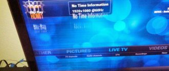
- If the screen says that there is no signal, most likely there is a problem with the antenna or input receiver of the device (it will need to be repaired or replaced).
- The panel is blocked, which means it is blocked due to a failure of the prescribed encoding and the corresponding settings.
- If there is an image with shades of blue, or a completely blue screen, then the display or corresponding matrix will most likely need to be repaired.
- The most complex restoration will be required in a situation where the motherboard has broken down; usually in such cases it requires a complete replacement with a corresponding device, since resuscitating the module is problematic and labor-intensive.
In this video you will learn how to repair a TV:
Today, there are various possible breakdowns that interfere with the proper operation of the device, but not all of them can be fixed independently. In such a situation, it is necessary to possess certain skills and knowledge. In some cases, repairing a device can be so expensive that it will be much easier to purchase a new device. All serious defects appear due to improper operation, either due to external influences or due to excessive voltage drops.
Important! In practice, all breakdowns can be fixed independently, but to do this, you must first determine the malfunction that has occurred based on the main symptoms.
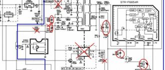
Description of the circuit diagram
A block diagram of a TOSHIBA TV on the S6E chassis, a circuit diagram, and oscillograms at control points can be downloaded here.
Power supply
The power supply (PS) is implemented on the basis of a pulse-width modulator (PWM), made on a Q801 chip of the STR-Z2154 type from SANKEN. The microcircuit contains a master oscillator, trigger circuits, comparison devices, protection devices and an output stage based on a powerful switching transistor. The microcircuit is powered in operating mode using a stabilizer on transistor Q872 from rectifier D864, C868. The voltage to the rectifier is supplied from winding 2-3 of the T862 transformer.
The rectified mains voltage +300 V from bridge D801 is supplied to the pin. 1 microcircuit. The output of the powerful switching transistor is connected to the pin. 14 microcircuits and then to winding 4-5 of the T862 transformer.
The IP produces two voltages: +20 V to power the audio circuits and +115 V to power the horizontal scanning. The output voltages are stabilized via a 115 V circuit using an error amplifier Q883 and an optocoupler Q862. The signal from the output of the phototransistor is supplied to the pin. 5 Q801 chips.
The Q840 chip implements a +5 V voltage stabilizer (1 channel) to power the microprocessor (MP) and a circuit for generating the RESET signal.
Line scan
Horizontal scan pulses with pin. 4 video processors Q501 are supplied to the base of the transistor Q402 and then, through the matching transformer T401, to the output stage assembled on the transistor Q404. The load of the output stage is the primary winding 1-2 of the T461 (TDKS) line transformer and the line coils of the deflection system. The supply voltages for the kinescope circuits are removed from the secondary windings of the transformer - anode, accelerating and focusing, filament voltage (pin 9), as well as the voltages necessary for the operation of other components of the TV:
- vyv. b: +27 V - for vertical scanning,
- vyv. 7: +12 V - used to generate voltages +9 V and +5 V (channel 2);
- vyv. 3: +200 V - to power the video amplifiers on the kinescope board.
From pin. 10 of the transformer, the feedback signal for the MP (HD, generated by transistor Q821) and the video processor (enters pin 6 of the Q501 video processor) is removed.
Overload protection of the output stage of the lines is implemented as follows: the current sensor in the +115 V circuit is resistor R470. When overloaded, transistor Q470 opens, the signal from its collector through transistors Q819, Q830, Q843, D846, Q846 bypasses the feedback circuit of the power supply and puts it in standby mode. Fuse F470 is used as an additional protective measure in case of control circuit failure.
Frame scan
Frame scanning is implemented on the Q301 chip (TA8403K from TOSHIBA). Frame sync pulses with pin. 53 video processor Q501 are supplied through resistor R301 to the pin. 4 Q301.
The pin assignments of the TA8403K microcircuit are given in Table. 1.
The current passes through the frame coils along the following circuit: pin. 2 chips Q301, L301, pin. 10 connectors P570, frame coils, pin. 9 connectors, C306, R305, common wire. The unit for forming the reverse motion of frame pulses provides an increase in the output signal range using an external capacitor C308.
Overload protection is implemented on the current sensor R370 and transistor Q370. When the +27 V power supply is overloaded, transistor Q370 opens and the protection signal through R373 and D370 puts the IP into standby mode.
Table 1
| Pin number | Purpose |
| 1 | General |
| 2 | Ramp voltage output |
| 3 | Power supply for the resuscitation unit |
| 4 | Clock input |
| 5 | Phase distortion compensator |
| 6 | Supply voltage |
| 7 | Output of the resuming block |
Tuner
Tuner H001 is controlled by the MP via the I2C bus. It provides reception of channels in the meter and decimeter wavelength range. The tuner receives the following supply voltages:
- +5 V (channel 2) - pin. 7;
- +9 V - pin. 9;
- + 32 V - pin. 2 (voltage +32 V is generated from voltage +115 V using a stabilizer on elements R101, D101, C101).
On the pin. 15 and 10 of the tuner are generated, respectively, video and audio signals. Sound signal output - pin. 10.
Depending on the version of the TV and whether it is equipped with a corresponding tuner, control signals can be supplied to different pins of the tuner. Selection is made using jumpers GJ02, GJO3, GJ04, GJO5, GJ23 and GJ24.
Video processor
The block diagram of the video processor is given in [1].
The Q501 video processor provides brightness signal processing, separation and decoding of color signals of PAL/SE-CAM/NTSC systems, obtaining R, G, B signals from decoded color difference signals, switching external and internal sources of audio and video signals to generate synchronization signals for vertical and horizontal scanning. The video processor is implemented on the TV1226 chip from TOSHIBA and is controlled by the MP via the I2C bus.
Full color video signal with pin. 15 of the tuner goes to the emitter follower QV01 and then to the pin. 47 video processors. After amplification, the signal arrives at its pin. 56 and then distributed to the following TV nodes:
- teletext decoder;
- emitter follower Q205, and after it: synchronization unit (pin 51 of the video processor);
- color block (pin 42);
- brightness channel (pin 45).
After processing in the brightness channel (rejection of color signals, delay of the brightness signal, binding to black level, sharpening), the brightness signal is sent to the pin. 37 of the video processor and further, through capacitor C514, to pin. 31 - to the RGB matrix. Color signals, in turn, after separation and decoding, are sent to the pin. 35 (RY) and 36 (BY) and further, also through capacitors, to the pin. 34 and 33 respectively. In the RGB matrix, three signals are obtained from the brightness signal and two chrominance signals: R, G and B. After adjusting the brightness, the RGB signals are sent to the pin. 12-14 and are sent to the kinescope board).
The video processor receives the following external signals, which are then further processed:
- external video signal (enters pin 1);
- external audio signal (pin 28);
- RGB digital signals from the microprocessor (menu, service modes) - pin. 18-21;
- analog RGB teletext signals (pins 22-25).
To adjust the black level (ABCL - pin 16) and raster distortion (curve correction - pin 5), a signal from pin is used. 6 line transformer T461.
To ensure the decoding of color signals and the operation of synchronization circuits, an X501 quartz resonator with a frequency of 16 MHz is used, connected to the pin. 40 Q501 chips.
Teletext decoder
The teletext decoder is made on a separate board based on the QT01 chip type SAA5281 ZP/E manufactured by PHILIPS SEMICONDUCTORS. The chip has a built-in memory of 8 kB. The decoder is controlled by the MP via the I2C bus. The decoder is powered by two voltages: +9 and +5 V (2nd channel).
Video signal from pin. 56 of the video processor goes to pin. N of the PT01B decoder connector and from there to a buffer stage assembled on transistors QT04 and QT05, which provides the required amplitude of the video signal (1 V). Next, the video signal comes to the pin. 9 decoder chips. Decoder outputs - pin. 16,17,18 (R, G, B, respectively) and the damping signal Ys (pin 20) QT01 through pin. A, B, D, E connectors are connected to inputs 22-25 of the video processor, which provides teletext display on the screen. The pin assignments of the SAA5281 chip are given in Table. 2.
table 2
| Pin number | Designation | Description |
| 1 | OSC OUT | Oscillator output 27 MHz |
| 2 | OSC IN | Oscillator input 27 MHz |
| 3 | OSC GND | Generator housing |
| 4 | Vss | General |
| 5 | Vss | General |
| 6 | REF+ | Positive bias for A/D converter |
| 7 | NC | Not connected |
| 8 | BLACK | Video black level |
| 9 | CVBS | Composite video input |
| 10 | IREF | Current offset for analog oscillator |
| 11 | Vdd | Supply voltage +5 V |
| 12 | POL | Signal polarity selection input |
| 13 | SSTV/LFB | Horizontal feedback input, used for synchronization |
| 14 | VCR/FFB | Vertical feedback signal input, used for synchronization |
| 15 | Vss | General |
| 16 | R | Teletext red output |
| 17 | G | Teletext green output |
| 18 | IN | Teletext blue output |
| 19 | RGB REF | DC input for determining the level of RGB signals |
| 20 | BLAN (YS) | Text blanking signal output |
| 21 | COR | Programmable output for reducing image contrast to ensure visibility of text on the image |
| 22 | ODD/EVEN | The output is used to provide progressive scanning and current correction through the vertical coils |
| 23 | Y | Teletext background signal output. Not used in this scheme |
| 24 | SCL | Serial clock bus I2C |
| 25 | SOA | Serial data bus NS |
| 26 | Vss | General |
| 27-32 | NC | Not used |
| 33,34 | NC | Not connected |
| 35-38 | NC | Not used |
| 39 | CLK EN | Generator output enable input signal for external devices. 8 is not used in this circuit |
| 40 | CLK O/P | 13.5 MHz clock output for external microprocessor. Not used in this scheme |
| 41-46 | NC | Not used |
| 47 | Line 23 | Output for mode indication Not used |
| 48 51 | NC | Not used |
Microprocessor
The QA01 microprocessor (M37222M4 manufactured by Mitsubishi Microcomputers) performs the main functions of controlling the TV: receiving commands from the control panel and keyboard on the front panel, turning the TV on and off, controlling TV units via the I2C bus, providing service modes, etc. The MP is powered by a voltage of 5 V ( 1st channel), generated by IP. To control the TV nodes, two I2C buses are used: one for the QA02 memory chip and the other for other devices.
The purpose of the main terminals of the MP is given in Table. 3.
Table 3
| Pin number | Designation | Description |
| 1, 21, 30 | GND, Vss | General |
| 3 | RMT OUT | Indication of receiving commands from the control panel |
| 4 | MUTE | Mute signal |
| 5 | EXT MUTE | Output mute signal |
| 7 | POWER | Signal to turn on the TV. A high level corresponds to operating mode, a low level to standby mode |
| 8 | LED | Indication of operating/standby modes |
| 9 | U/V | Tuner band switching signal |
| 11 | SCL 0 | Serial line of I2C bus clocks |
| 12 | SDA 0 | I2C bus serial data pin |
| 13 | AFT IN | AFC input signal |
| 16 | KEY IN | Input signal from TV keyboard. The pressed key is determined using weighting resistors connected to the buttons. The read signal is converted into a digital key code using an analog-to-digital converter |
| 17 | KEY A | Output signal to VIDEO and MENU buttons |
| 18 | KEY B | Output signal to the CH and VOL buttons |
| 19 | SGV | The service video signal enters the video processor through the VIDEO IN connector. Used in service mode |
| 20 | S.G.A. | The service audio signal enters the video processor through the AUDIO IN connector. Used in service mode |
| 21 | N.S. | Not used |
| 22 | OSВ R | Digital red signal output. Displaying menus and service modes. Enters the video processor |
| 23 | OSD G | Digital green signal output. Displaying menus and service modes. Enters the video processor |
| 24 | OSD B | Digital blue signal output. Displaying menus and service modes. Enters the video processor |
| 25 | OSD Ys | Digital blanking output |
| 26 | Hsync | Feedback horizontal sync input |
| 27 | V sync | Feedback vertical clock input |
| 28,29 | O.S.C. | Generator connection terminals for display unit (OSD) |
| 30 | GND | General |
| 31,32 | Xin, Xout | Generator connection pins for internal microprocessor timers, I2C bus, etc. |
| 33 | RST | RESET signal input. Active level - low |
| 35 | RMT IN | Signal input from remote control |
| 36 | MAIN SYNC | Synchronization signal input from the video processor synchronization unit |
| 37 | SCL1 | Serial line of I2C bus clocks |
| 38 | SDA1 | I2C bus serial data line |
| 42 | Vdd | Supply voltage +5 V |
Sound processing path
The selected audio signal from tuner H001 (pin 10) is sent to pin. 27 Q501 video processor. On his pin. 28 an external sound signal is given. The video processor switches one of the selected signals to the pin. 29, from where it is supplied to pin. 7 Q610 low frequency power amplifier (TDA2611A). Output signal from pin. 2 amplifiers are supplied to the dynamic heads through the coupling capacitor C613.
Transistor Q612 provides a delay in turning on the sound when the TV is turned on, and Q611 mutes the sound via the MUTE signal from the MP, Q620 and QS01 mute the sound supplied to the AUDIO output connector via the EXT MUTE control signal.
The pin assignments of the TDA2611 amplifier are given in table. 4.
Table 4
| Pin number | Designation | Purpose |
| 1 | Vcc | Supply voltage +20 V |
| 2 | OUT | Exit |
| 3 | Nc | Not connected |
| 4 | GND | General |
| 5 | BST IN | Feedback input |
| 6 | GND | General |
| 7 | IN | Entrance |
| 8 | R FLT | Compensation input |
| 9 | F BACK | Feedback output |
Service modes
To adjust and configure the TV, two modes are used:
- service mode;
- setup mode.
To enter service mode proceed as follows:
- press the MUTE button on the remote control once;
- press the MUTE button a second time and hold it pressed;
- While holding down the MUTE key on the remote control, press the MENU button on the TV.
In service mode, the “S” symbol is displayed in the upper right corner of the screen.
To switch between service mode and setup mode, use the MENU button on the TV.
Menu items are selected using the CHANELL buttons.
The values of the selected parameter are changed using the VOLUME buttons.
To exit the service mode, you must turn off the TV.
Table 5
| Address in hexadecimal format | Name | Hexadecimal value |
| 68 | RCUT | 20 |
| 69 | GCUT | 20 |
| 06A | B.C.U.T. | 20 |
| 06B | GDRV | 80 |
| 06С | BDRV | 80 |
| 06D | CNTX | FF |
| Both | BRTC | 80 |
| 06F | COLC | 80 |
| 070 | TNTC | 40 |
| 073 | SCNT | 07 |
| 087 | HPOS | 0A |
| 088 | VPOS | 04 |
| 089 | HIT | 40 |
| 08E | VLIN | OF |
| 097 | SBY | 08 |
| 098 | SRY | 08 |
To initialize the memory contents after replacing the QA02 chip, you must perform the following steps:
- enter service mode, select “register”;
- While holding down the CALL button on the remote control, press the CHANELL button on the front panel of the TV.
Warning : Memory initialization must be carried out only after replacing the QA02 chip.
Table 6
| Key | Designation | Purpose |
| CALL | Detail | Menu Detail |
| 1 | R CUT | Black level for red channel |
| 2 | G CUT | Black level for green channel |
| 3 | In CUT | Black level for blue channel |
| 4 | CNTX | Adjusting Contrast |
| 5 | COLC | Adjusting color thickness |
| 6 | TNTC | NTSC Hue Correction |
| 8 | On/off test beep | |
| 9 | Self-diagnosis | |
| -/— | On/off horizontal stripes | |
| IN | Select PAL/NTSC/No signal test signal (no cables should be connected to the IN connector). A total of 14 PAL and 14 NTSC test signals are available |
The default values of adjustment parameters (in the memory chip) are shown in table. 5.
In the setup mode, the remote control buttons perform special functions (Table 6).
The list of test signals is given in table. 7.
Table 7
| Name of test signals | Display | Purpose |
| • Red single color • Green single color • Blue single color • Black single color • White single color | Display the corresponding color on the screen | Adjusting color purity |
| • W/B adjustment | Dark screen with a white rectangle at the top | Adjusting the white balance Before adjusting, set the contrast to 40, brightness to 20. The balance in the dark part of the screen is adjusted by changing the values of R CUT, G CUT and B CUT. Balance in the light part - by changing G DRV and B DRV |
| • Black cross-bar • White cross-bar | Cross | Adjusts the position of the center of the image on the screen. HPOS - horizontal shift; VPOS - vertical shift |
| • Black cross-hatch • White cross-hatch | Net | Vertical size adjustment Adjustable by changing the HIT value |
| • Black cross-dot • White cross-dot | Stitched mesh | Adjusting the mixing |
| • H signal white • H signal black | Vertical stripes on the screen | Control of black and white transitions |
The self-diagnosis menu displays the information shown in the table. 8.
To reset the protection counter, hold down the CALL button on the remote control and press the CHANELL b button on the front panel of the TV.
Table 8
| Position | Normal value | Description |
| (SELF CHECK) | — | Self-diagnosis mode indication |
| 239OXXXX | — | Processor number (QA01) |
| POWER | 0 | Number of protection circuit operations |
| BUSLINE | OK | SDA-GND - SDA line is shorted to the body; SCL-GND - the SCL line is shorted to the body; SCL-SDA - SCL and SDA lines are closed to each other |
| BUS CONT | OK | Qxxx NG - device error No.xxx |
| SYNC | OK | NG - video signal is not normal |
Doesn't turn on
In practice, this situation is the most common. Such a malfunction may be the result of a short circuit in the circuit, a malfunction of the processor, or, in addition, a failure in the control system. In such a situation, you will need to open the protective cover, and then use a controller or tester to identify the corresponding malfunction in the form of a short circuit present. Here it is necessary to open the circuit that is blocked due to the protection being activated. This troubleshooting is performed through the traditional reinstallation of all resistors that contributed to such a manifestation. In the case of the control and processor, you will have to completely restart the device by doing a mass reset when you disconnect the motherboard. If the indicator does not light up when you turn on the power, then most likely you will have to change the control unit altogether.
Important! When working with internal circuits, it is necessary to completely de-energize the TV so as not to provoke a recurrence of the malfunction, and in addition, not to further aggravate the situation.
Video text
A Toshiba 32KL933R device arrived at our service center with a malfunction: no image, there is sound. The problem is with the screen backlight, namely the LED strip. We replace it with a new bar, the client is satisfied. We have these planks for sale, if you have any questions, please contact us.
We have a large store of spare parts for TV repairs https://www.avito.ru/vltehnik
We cooperate with workshops, write to us and we will work with you at other price tags.
- Author: Maria Sukhorukikh
Rate this article:
- 5
- 4
- 3
- 2
- 1
(0 votes, average: 0 out of 5)
Share with your friends!
No image
Another common cause of Toshiba TV malfunctions. Under such circumstances, there is a possibility of failure of the corresponding module, or of connecting the display to the transfer circuit. Here you will need to find the appropriate diagram, and then use a special tool to determine the presence of short circuits or lack of contact. Subsequently, it is necessary to restore the conductivity of the signal so that the image can be transmitted to the screen. Additionally, a failure in the settings may occur, in which case you will have to roll them back to the factory state. If the cause of the breakdown is the device matrix, then it must be replaced with a corresponding working module. As in any other situation, all work is performed with the power turned off.
The indicator is flashing
If the indicator blinks, it means that the TV itself is diagnosing the type of problem. Typically the red light flashes a certain number of times. In this case, you need to open the operating instructions for the device and find the section where the types of faults and their indication are indicated. And, based on this, take the necessary actions.
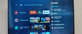
Another option that can cause a similar symptom is that the TV is connected to a computer as a monitor. If the connected computer has entered “sleep mode” or is turned off, when you turn it on from the remote control, the device will blink for several seconds. Alternatively, the TV is connected as a second monitor, but not as the main one.
You need to wake the computer from Stand By mode (move the mouse or press a button on the keyboard) or start it by pressing the power button. Basically, the TV works. It just doesn't show an image.
No sound
This type of breakdown occurs most often, since audio conductors have the least load resistance. A common reason here is when the corresponding contact is broken, which is why it is necessary to fully restore it in all damaged areas. In addition, the malfunction may be a breakdown of the speakers themselves. Here a full replacement is required, since it is almost impossible to restore the devices. Also, a defect is periodically observed in the corresponding sound card, which is why it undergoes a full inspection and diagnostics, after which it is resoldered or completely replaced with another device. The last possible breakdown is the lack of a signal from the main distribution module. As a rule, in such a situation, a full reset of settings and encodings to factory values is carried out, or replacement or overhaul of this accessory is carried out.
There may be no sound for several reasons
Important! The sound components are separate from all other modules, which makes it much easier to identify a breakdown and fix it, but this is not always acceptable due to the complex design of the circuit.
Simple Ways to Fix a Black TV Screen
The breakdown appears at different times - on old and new TVs. If in your case the warranty period has not yet expired, find the coupon and contact the store where the device was purchased.
This will provide free repairs if the damage is serious and cannot be easily fixed at home. If the screen is dark but you can hear sound, try checking the following items:
- The antenna cable may not be connected tightly to the jack on the TV. It may be broken or not fully inserted. Try reconnecting it to the TV and check the result;
- Another type of cable is also connected to the TV, which transmits the signal from the tuner. The end is divided into three parts, each plug has its own color: white, red, yellow. Separately, they are responsible for outputting image, sound and antenna signal. If one of them is turned off, the TV may not show;
- Most digital tuners also have the ability to receive radio signals. On the remote control there is a special button for switching to radio channels. You need to try to turn off the mode; perhaps you accidentally turned it on on the remote control;
- Short-term malfunctions occur that can be resolved by turning the TV on/off.
If your home has an AC stabilizer, you must connect the device to the network using it. If you manage to get rid of the malfunction in this way, then you were able to determine the cause - low voltage.
It is recommended to use all household electrical appliances through a stabilizer in regions where voltage interruptions occur frequently. Mostly these are small towns and villages.
Motherboard repair
This device is the main one in the TV, which is responsible for the distribution of all functions, as well as the correct control of the device. This accessory has appropriate protection, which is why in practice the failure of the board occurs only in emergency situations due to excessive temperature changes. Basically, such a device is subject to replacement, since when high voltage hits, the protection is triggered; if this does not happen, then all the contacts present begin to melt due to excessive load.
During the restoration process, you will have to completely remove the board, and then check it for possible melting or broken contacts. Here repairs are allowed by soldering damaged elements. Such a device is subject to restoration in the case when no more than three components have undergone deformation. In another situation, trying to repair the device is not rational and you need to replace it. Provided that the protection on the device simply worked, you will have to switch it to the appropriate mode, then install the device in place and check the device for functionality.
Important! If you decide to replace the board, you will need to find the appropriate device that is manufactured for a specific model or series of TVs, since if you connect an inappropriate version, the TV will not work correctly.
Advantages of cooperation with the service
If your Toshiba TV does not turn on, then the company’s highly qualified technicians will diagnose and make high-quality repairs in the shortest possible time.
.
can visit your home
. This eliminates the need to independently organize the delivery of the device to the workshop.
A guarantee is issued for the work performed
. This emphasizes the professionalism of the employees.
All Toshiba brand models are repaired.
Fast execution and reasonable cost
– the business card of the service.
Attentive attitude towards each client.
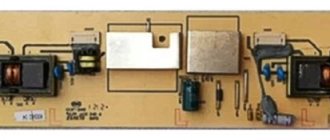
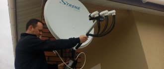
How to replace a transformer
This device is responsible for distributing power to all components of the device. If it does not work correctly, system failures of all parameters begin. In order to correctly replace this structural element, the following algorithm of sequential actions must be performed:
- First, the protective cover is removed from the TV to provide full access to the internal components of the device.
- The next step is to completely remove the board on which this device is installed.
- Immediately before this, all existing wiring from the board with the transformer is disconnected.
- Subsequently, damage to this element or to the existing contacts between the device and the board is assessed.
- It is necessary to select an equipment option that is appropriate in terms of power, which can be installed in the TV.
- Next, the old transformer is removed from the corresponding board, followed by installation of a new device.
- As a rule, such devices are mounted on a solder, which is made to numerous contact groups.
- Subsequently, the device must be checked to ensure that the entire installation of the device has been carried out correctly.
- Next, all components are installed in place, followed by connecting the necessary wiring.
At the final stage, all you have to do is check all the technical equipment for functionality. It should be understood that each transformer is equipped with protection, like the motherboard, which is necessary to turn off the power in the event of an excessively high load. That is why, immediately before installing the accessory, this component of the circuit must be completely restored. Only after this is a trial test of the entire television device performed.
Important! Any work on repairing and restoring a Toshiba TV must be carried out with the power turned off, which will avoid the possible occurrence of additional malfunctions due to errors.
Today, there is an excellent opportunity to restore the technical equipment yourself, without resorting to the help of specialists, however, it is recommended to do this only if you have the necessary skills and appropriate knowledge of the structure of each component of the TV. In another situation, it would be better to entrust such work to professionals, since incorrect repairs can lead to even more significant consequences. Here we should separately highlight the need to reset the settings in the event of any restoration work in order to eliminate existing errors.