A large number of different connectors are used to connect blocks and assemblies of electronic equipment. Some connectors can contain dozens of pins. To connect most blocks into a single unit, structures with only two contacts are used. One is information or signal, and the other is general or “ground” and is designated in the diagrams as “GND”.
Entrance/exit “Tulip”
When choosing connectors for connecting cables, you need to pay attention to the manufacturer. Products from some companies from the Asian region are of poor quality. The use of low-quality plastic in the connector design leads to the fact that the central rod, to which the signal wire fits, loses the rigidity of its fixation. This results in an alternating contact in the connection. It is better to choose connectors with a textolite or ceramic core. The screw clamp is an unreliable connection. It is best when the wire is fixed by soldering. Product bodies made of plastic are used only in budget cables. Reliable RCA connectors have metal housings.
RCA input
Most often, the RCA or “Tulip” connection is used in consumer electronic equipment to switch input and output signals. The RCA audio/video input provides the transmission of audio and video signals in accordance with the accepted standard for frequency, current and voltage. The “Tulip” connector is a connector consisting of two elements. On household appliances, the input and output sockets are located on the rear wall of the case and differ in markings and colors. Audio input connectors or RCA audio input are marked “Audio in put” and have the following colors:
- Left channel – white
- Right channel - red
The plug and socket for switching the video signal are always color coded yellow. The “Tulip” input, compared to digital interfaces, does not provide high color accuracy when transmitting a video signal from an external source to a TV. However, all household television receivers are equipped with such sockets.
How to turn it on without a remote control?
Of course, the easiest way is to use the remote control, press the corresponding button and turn on the AV mode, and then the desired channel. But it often happens that the TV control device is missing or broken. The best thing to do in this case is to go and buy a new remote control. But in life it happens that the remote control is broken, and there is an urgent need to use the AudioVideo mode. There are two ways to turn on the TV if you don't have a remote control:
- use the side panel of the TV;
- use a smartphone.
The first option is used most often in such situations. Everyone knows that each model has buttons on the back or side panel for control: switching channels, adjusting the sound, activating/deactivating the TV. Usually the buttons are quite small and colored in the color of the body, so they are difficult to notice.
Important! You need to carefully examine the entire TV; there are buttons on every TV model.
There should also be a button to switch between AV and standard modes. They are located differently in different models, so it is better to read the instructions and find information on the location of the switch button. Sometimes you need to use the button control panel to go into the settings and switch modes there. All this information is written in the instructions that come with each TV.
The last method, which involves using a smartphone, is still rarely used. Since the TV must have a control function via an application on the phone. All modern and latest models are equipped with this technology, however, the price for them is appropriate.
Important! You should install an application on your smartphone that will allow you to control the TV.
To switch from standard mode to AV, you should go to the application on your own smartphone. There should be “Settings” or “Mode Switching”. You need to go there and switch the TV to AV operating mode. Do not forget that different manufacturers make such applications differently. Therefore, there will not be detailed instructions for a specific model here.
Description RCA
| RCA plug |
|
RCA jack or composite (also called phono connector, or CINCH/AV connector, and also colloquially “tulip”, “bell”, AV connector) is a connector standard widely used in audio and video equipment.
The big disadvantage of such connectors is that when connecting, the signal contact pair (with voltage) is connected first, and only then the housing contacts. This can cause damage to devices at the time of connection if there is a potential difference between the cases, which often happened when connecting TVs to the TV output on video cards.
A standard RCA plug (in slang for “male”) looks like a central metal protruding contact pin with a diameter of 3.2 mm (3.18 for a 0.25 inch size), an outer open length of 9.0 mm (9.52/7. 92 mm for 0.375/0.312 inch sizes), with an internal closed length of 6.0 mm (5.56 for 0.219 inch size), surrounded by a metal round rim (8.0 mm minimum inner diameter; 8.33 for 0.328 inch size). The outer diameter of the rim depends only on its thickness and is not standardized.
The RCA (slang for "female") jack, typically a panel connector that the bezel fits over, has an outer diameter of 8.0 mm (8.33 for the 0.328-inch size) and a depth of 7.50 mm (7.14 for the 0.281-inch size). ), so the rim crimping jaws must have a slightly larger internal diameter.
In inexpensive versions, the space between the connector/collet and the rim/housing (internal insulator) is filled with simple plastic or polyethylene, in mid-price ones - with textolite washers or similar ones made of pressed fiberglass, in expensive ones - with heat-resistant Teflon or ceramics.
One of the main disadvantages of inexpensive connectors is their low heat resistance. Soldering cables with a cross-section of 0.823 mm² (18 awg) or larger requires a very long warm-up time at standard solder melting temperatures of 250 ° C - or much higher temperatures of the soldering iron tip, in order to increase the cumulative heat capacity of the tip, sometimes up to 500 ° C.
Used inputs on TV
Seal
Antenna and AV TV input
On old TVs there was only one input - analog, antenna, high-frequency. Now modern TVs have not one TV input, but several, and it seems that this is overkill, especially for LCD TVs. However, all this is for the convenience of users.
In my opinion, the optimal option for CRT TVs is 3 TV inputs. At the back, for example, for satellite or digital (which appeared relatively recently) receivers and DVD players, and at the front or side for a video camera.
LCD TVs have even more inputs; in addition to analogue, they have a digital input.
Analog TV input.
These include:
- RF input;
- A/V, composite;
- S-Video;
- SCART;
- VGA.
RF input – antenna. This type is used to connect antennas, VCRs, and sometimes cable and satellite “boxes” and DVDs to the TV. The quality of the prima signal through this connector is the lowest.
A/V input. A familiar type of connection known to us under the name “tulip”. Usually yellow-white + red three. Allows you to improve image quality. Information about audio and video is not transmitted entirely over a single channel, but separately for audio (white - red) and separately for video (yellow).
S-Video input. Not available on all TVs. Information about color and contrast is transmitted separately here. S-Video is a widely used analog contact to this day; very often these connectors can be found on DVD panels, game consoles, etc. It is also quite often used as an alternative output by manufacturers of computer video cards.
SCART. This input, which can accommodate 21 contacts, is now common almost everywhere in Europe. Today, SCART, depending on specific specifications, can transmit both audio and video, analog and digital signals.
VGA - input. It is found mainly on new TVs, since the main function of this 15-hole input is to serve as a contact for connecting a personal computer. Therefore, the VGA input option on a TV is usually identical to the input on an analog computer monitor (D-sub 15-pin).
Digital
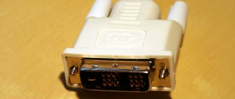
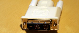
These include DVI and HDMI inputs. These outputs are designed to transmit HDTV-quality digital video without any compression. HDMI differs from DVI primarily in that, in addition to digital video, it can transmit multi-channel digital audio. And, although there are currently quite a lot of varieties of both interfaces, most of them are perfectly intercompatible and can be used together using simple adapters. In addition, both interfaces are great for connecting a computer to a PC. DVI and HDMI are notorious for supporting the HDCP protocol, which protects licensed content from unauthorized rewriting.
Basic colors of tulip wires
"Tulips" are known in one-, two- and three-plug designs. However, the triple variety is more common. The dual audio cable consists of one red plug and one white, while the triple variant has the addition of yellow.
The basic color signals are yellow, white and red. Understanding what the colors of the tulip wires mean and how to connect them correctly is not difficult.
The yellow plug is used to connect video; white – for audio signal on the left side; red – for the audio signal of the right jack. In this case, take into account the correspondence of the color of the wire with the color of the input on the device.
If the TV has inputs with the same colors, then use the following decoding:
- on the tulip wire and the TV you need to find the inscription “IN” (which means “in”) or two arrows, also on the TV input there may be the designation “AV2”, and connect the wire;
- The designations on the TV may be “V” - video connection, “L” - left audio input, “R” - right audio input.
Thus, knowing what tulip wires are used for and what color is responsible for what, we connect: the yellow plug to the V-connector, the white one to the L-input and the red one to the R-input on the TV.
If there are three tulip plugs, and the TV has two inputs, then connect only yellow (to the video signal) and white (to receive a mono audio signal). The red wire is not used at all.
RCA output (Tulip)
What is RCA audio/video output. “Tulip” type connectors are used in household appliances to connect individual units into a sound complex and to connect speaker systems. The audio output connectors are marked “Audio out put” and have colors similar to the input signals. If the low-frequency amplifier is intended for multi-channel sound reproduction, then the sockets on its body are color coded as follows:
- Front left channel - white
- Front right channel - red
- Central speaker system - green
- LF subwoofer – purple
- Side left channel – blue
- Side right channel – gray
- Rear left channel – brown
- Rear right channel – light brown
Each output is connected to its own speaker system, which provides multi-channel sound. This connection scheme is most often used in home theaters. Some models of household appliances use modern interfaces such as DVI-I and HDMI. Such interfaces are used in personal computers, but televisions may not be equipped with them. In order to connect a laptop to a television receiver, you have to use an adapter - an adapter from HDMI to RCA.
On an RCA cable, four cables with sockets extend from the HDMI connector. White and red are RCA audio outputs corresponding to the left and right audio channels, a video signal is transmitted through a cable with a yellow connector, and the black connector is intended to supply power voltage to the signal converter circuit.


