Attention
Page 2
- Image
- Text
ATTENTION!
Thank you for purchasing our company's product.
To achieve the best performance, please read the instructions carefully. Save the instructions for future use.
AND
and
ATTENTION: TO AVOID DAMAGE
ELECTRIC SHOCK, NOT
DISASSEMBLE THE UNIT, THERE
ARE NO USER CONTROLS INSIDE
and
An image of a lightning bolt with an arrow at
the end in an equilateral
triangle warns
alerts the user to the presence of dangerous
voltage within the enclosure that may be of
sufficient magnitude to cause
electric shock.
An exclamation point within
an equilateral triangle indicates important operating instructions in accompanying the device
.
Supply voltage ~ 220 - 240 V, 50 / 60 Hz.
BBK SMP129HDT2
Quite recently, I already wrote about the installation and configuration of terrestrial digital television according to the DVB-T2 standard in a private house in the Moscow region. But that was about a TV that was already equipped from the factory with a DVB-T2 standard module and capable of receiving all the necessary channels out of the box.
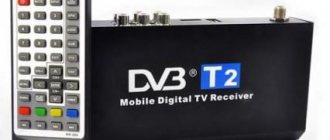
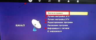
But what should the owners of millions of old televisions, maybe even CRT ones, do? Throw it away and buy new? There's no need to rush. In order to upgrade your old TV set into a new modern high-quality digital TV signal receiver, you just need to connect a digital set-top box with DVB-T2 to it.
Of course, your location must be within the coverage area of the digital signal broadcast and the antenna connected to the TV must be UHF and provide at least some reception of the signal from UHF channels. Otherwise, you should first decide on the antenna, and only then set your sights on the set-top box. There are a number of DVB-T2 receivers on the market, designed as set-top boxes. They are produced both here, in Russia, and in a distant country in the east.
In terms of quality and functions, they are not much different, because they are made using almost the same components. Globalization, motherfucker, go ahead! But if you look at it, then more is not required.
These functions are even a little too much for the average household consumer. It would be enough to just watch channels in the DVB-T2 standard and that’s it. It's good, of course, but it doesn't make any sense. You can console yourself with the hope that someday, in my Vydropuzhsk, someone will launch commercial digital terrestrial television, I will buy a module and will enjoy paid channels. Yes, and other standards, if you really have them, then such a receiver is worth considering. Otherwise, as usual, it’s money down the drain and dust in the eyes.
What is DSP, Introduction, Surround sound dolby pro logic
Page 4
- Image
- Text
What is DSP?
Introduction
Surround sound Dolby Pro Logic
Welcome to the incredible world of digital
home entertainment.
Many of the new features may be unfamiliar to you, but they are
easy to use.
Latest technologies such as Dolby Digital and DTS may be new in
your home, but you've probably already experienced
the stunning realism they create in large movie theaters.
To make your listening experience even more
exciting, this unit is equipped with
a huge number of digital acoustic effects called digital sound
fields.
DSP programs seem to transport you from your room to an outdoor arena, a European church or a jazz club. Take a moment to read this information to fully enjoy the effects of DSP
Digital Sound Field Processing DSP
Technological innovations in the field
Audio reproduction over the past 30 years
has achieved high purity, accuracy and power of sound.
However, something remained missing: the atmosphere and acoustic environment
public places.
Engineers studied the nature of sound and measured sound parameters in crowded places. Some DSP models are created using the acquired data, and some have
additional digital algorithms added.
Dolby Pro Logic has been around since the mid
-70s and in home systems since the late 80s, and is still very
popular today. It uses 4 separate channels
to reproduce dynamic realistic
Music effects: two main channels
(left and right), a center channel for
dialogue and a rear channel for special
sound effects. The rear channel reproduces sound in a narrowed frequency range.
Most videotapes and laserdiscs
contain Dolby Pro Logic tracks, as well
Many television
broadcasting services are also doing so.
The Dolby Pro Logic decoder built into this unit provides even more
high-quality sound processing than
standard analog processors.
Dolby Digital
Dolby Digital - a new generation of systems
Dolby surround sound.
It is designed for 35mm films using
low-bitrate audio encoding.
Dolby Digital - digital surround system
sound that gives you independent
multi-channel audio.
The system consists of 5 full channels and is sometimes called
a “3 / 2 configuration”: three front channels (left,
center, right), and two rear channels.
The sixth channel is intended only for reproduction of low-frequency sound and
special effects.
(Called subwoofer or LFE).
In a 5.1 configuration, this channel is labeled 01.
TV repair in Russian/forum: BBK SMP129HDT2 – TV repair in Russian/forum
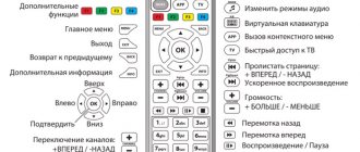
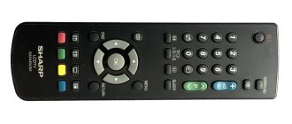
The transition from analog television broadcasting to digital DVB-T2, adopted as a federal standard in the Russian Federation, influenced not only the computer TV tuner industry. The fleet of TVs either without support for digital terrestrial broadcasting or with support for the first version of DVB-T turned out to be more than impressive, while many models simply did not have time to become obsolete in terms of diagonals and resolutions. Delivery set The compact box has a traditional BBK white and blue color scheme, explanatory inscriptions are localized. In addition to the receiver itself, the kit includes: remote control; 3 RCA - 3 RCA composite cable for analog video and audio connections; user guide. The device is available in two colors - Black and Dark Gray, the second option was tested.
unlike Dolby Pro Logic, also called...
Page 5
- Image
- Text
unlike Dolby Pro Logic, also called
“3/1 configuration” Dolby Digital has two
surround channels, called stereo or split surround, each representing a full audio channel.
Wide dynamic range audio
from five full channels and digital audio processing create an incredible
experience you've never experienced before.
The Dolby Digital system, as mentioned above, includes
5 full independent channels, but recording, nevertheless, can be simple stereophonic or even monophonic. Such recordings in Dolby Digital format can sometimes be found in stores.
Laserdiscs and DVDs are
home audio formats that can be
loaded with Dolby Digital information.
In the near future, Dolby Digital will be used in
DBS, CATV and HDTV systems
DTS surround sound
DTS was developed to
replace analog movie soundtracks with 6 separate digital channels. Currently, DTS is used in many home theater systems.
The DTS system consists of 6 channels of 20-
bit audio of excellent quality. Technically, this system implements 5 wideband channels and one channel specifically for reproducing low-frequency sound.
My blue-eyed girl, I can’t live a day without you. My blue-eyed girl, Well, tell me that you love me...
Probably every owner of this amplifier involuntarily began to hum these words, about a year after purchasing it.
And all because exactly a year later (for some a little earlier, for others a little later) this wonderful receiver stopped working and refused to turn on - for no apparent reason. EVERYONE had the same symptom - Just yesterday everything was working well. We listened and turned it off... And this morning it won’t turn on! Without reacting to any control, it coolly shone with a blue LED. A trip to the service center was guaranteed for everyone! What happens behind the scenes in the service itself is hidden from the eyes of clients. But after his visit, the lucky owners could again enjoy the proper operation of their devices. The irony of the whole situation is that this was not the only trip to the repair experts. After exactly the same period of time, the Amplifier showed all the same signs: the diode was shining and did not turn on... Among the service technicians, at first, there was also no absolute understanding of the cause of the malfunction. Checking all the parts did not reveal any faulty ones. Replacing the control controller with another one, with the latest firmware version, also did not give any results. Official support (and this is in China) did not give any explanation, so this is the reason. The experts went to great lengths to find out the reasons for the widespread appeal of people to the service... Gradually, “the place from which the legs grow” began to emerge. It turned out that the amplifier came to life again if the small memory chip in it was replaced with a new one. Without going into too much detail, the first “wave” of clients who contacted the service were made happy by this very thing. Are there really defective memory chips in the entire batch of receivers? Perhaps, but no! Testing of the soldered microcircuits showed that they work perfectly, the data in them is successfully erased, written and read. If such a microcircuit is reinserted into the receiver, having previously erased all recorded data from it, the device turned on and worked as if nothing had happened! But after some time, people began to contact the service again. And it has already become obvious that the root of all evil is in the algorithm of the amplifier. Servicemen made corresponding requests to the manufacturer. In response, they received access to download fresh, corrected firmware. This receiver model has a sibling - an amplifier with a built-in radio receiver, which was displayed in the model name as an additional letter “T” (AV 212T). Although visually they are the same, the firmware in them was still different (due to the additional module - the radio receiver). It is not known what the Chinese fixed in the firmware, only one of the “brothers” was luckier (this is a model with a tuner) and after updating the firmware, the problem described above no longer appeared. But the second “brother” was less fortunate - the new “vaccine” did not help him. Since this malfunction was extended over time (about a year passed between breakdowns), no one began to understand anything. In addition, this model is morally outdated... As a happy owner (of a model without a tuner), I contacted the service myself a couple of times. Then, during the next strike of my receiver, I decided to figure it out myself and “ONCE AND FOR ALL” fix the device. I read a bunch of forums on the Internet where people shared their successes and methods of resurrecting devices that had gone to another world. Someone simply soldered in a new memory each time, someone soldered a socket under the microcircuit for easier removal and each time erased its contents with a programmer... Someone managed to lean the capacitor against the terminals of the memory chip at the moment of switching on. This method really works - I tested it))) But it is extremely unstable, which is very inconvenient. Firmware with the big words “CORRECTED”, “CURIED” or “NEW” was publicly available on file hosting sites; of course, I downloaded many of them. Checking the HASH amounts showed that this is either the very first firmware with which these amplifiers entered the market, or the very same firmware that the developers “corrected”. But I had the same “corrected” firmware, which once again blocked the device. All this did not suit my desire - “ONCE AND FOR ALL”... And one day I came across an article where the author described his solution to this problem. Having found out that the firmware was to blame, he read it from the microcontroller, disassembled it and began checking the program algorithm step by step. I found out that when the power is turned on, the controller accesses the memory (that same separate microcircuit), reads the values of certain cells and checks them against the condition... This is where all the magic happens! If one of the read values is not equal to zero, then the program then ends up in an empty loop, thereby looping “forever.” Why this was implemented by the engineers is not clear. The author corrected the code by changing the check condition so that the program would never fall into this empty loop and would continue to execute. And it really helped! It turned out that 2 memory cells of the microcircuit (with addresses 0x50 and 0x51) store the number of times the device was turned on. Because one cell is 8 bits - the maximum number that can be stored in it is 255. Upon reaching this number and then adding one to it, the cell is “zeroed” and counting starts from zero. In our case, when the first cell with address 0x50 is reset, the second cell 0x51 is increased by one... i.e. after that, the next time you turn it on, a check will be made to see if this cell is equal to zero, and the program will loop. The amplifier will not turn on! Great respect to the author of that article! Taking off my hat! ))) Unfortunately, I did not find a link to his article, because... it was a long time ago. HERE IS HIS ARTICLE. And another irony is that he did this for an amplifier model with a radio receiver and I could not use its corrected firmware))) I don’t know how to disassemble. Therefore, based on that article, I decided to do a little trick and “collectively farm.” The size of the AT24C02 memory chip and the ATtiny13 microcontroller are the same. Moreover, their nutritional legs are the same.
This gave me the idea to put the ATtiny13 on top of a memory chip and force it to check the contents of memory cell 0x51 every time the power is turned on. And if there is not “zero” there, then reset it to zero.
The controller communicates with the memory via the I2C bus. I was wondering if it was possible to connect another master device to the bus and work with the memory? As far as I understood, at the moment the power is turned on, the amplifier’s microcontroller is initialized, which takes some time, and only then accesses the memory, reading values from it. I wanted to check the memory before the controller starts doing it. To measure time I used an Arduino. I connected one of its inputs to the 5v line of the amplifier board. And the second is on the I2C bus data line. Thus, when 5v power appeared, the arduino turned on the time counter, and when data appeared on the I2C bus, it stopped it. Such measurements consistently showed a time interval of 89-90 m.s. which might not have been enough for the intended fraud. Just for fun, I connected the oscilloscope to the SDA data line.
It turned out that memory polling occurs constantly! All articles on working with the I2C bus describe the situation with one master and several slave devices. But as it turned out, you can use 2 master devices. In this case, there is no conflict between them. Priority is distributed according to the principle: “whoever gets up first gets the slippers.” To test the algorithm, I also used an Arduino - setting it up to work with I2C. At first, I simply soldered the wires to the SDA and SCL pins of the memory chip and tried to read data from it.
For proper operation of the I2C bus, both pins must be “pulled up” to the power supply with 5v resistors, but they were not on the diagram. Therefore, the first attempts to read data from memory did not lead to anything.
Soldered 10 kOhm resistors and everything worked! Arduina began sending data from memory cells to the terminal. I read both cells 0x50 and 0x51 at once. Each time the amplifier was turned on, the value of cell 0x50 increased by one. Next, for testing, I forcibly wrote a 1 at address 0x51 and tried to turn on the amplifier. And it didn't turn on! Having written the “zero” back into it, everything began to work as it should! The algorithm has been confirmed and you can start writing working firmware. Having created a new project in CodeVisionAVR for ATtiny13, we set it to a frequency of 4.8 MHz. It is at this frequency that it will operate from the internal clock generator (this will be adjusted later by FUSE bits). We also configure work with I2c and configure microcontroller pins 5 and 6 (PORTB.0 and PORTB.1) - corresponding to the pins of the SDA and SCL memory chips. Bus bitrate - leave the default at 100 kHz. After initialization, the controller (ATtiny13) will forcibly keep the SCL line pulled to ground. You can verify this by simulating its operation in Proteus.
Therefore, immediately after the controller initialization code, we write: i2c_stop(); All. Now our controller does not interfere with the operation of the amplifier controller.
Reading data from cells:
delay_ms(200);
i2c_start(); //send the “start” command to the i2c bus
i2c_write(0xa0); //send the address of the memory chip to the bus
i2c_write(0x50); //send the address of the cell being read to the bus (0x50)
i2c_start();
i2c_write(0xa0 | 1);
eep50=i2c_read(0); //receive data from the line and save it to the variable eep50
i2c_stop(); We do the same to read the second memory cell:
i2c_start();
i2c_write(0xa0);
i2c_write(0x51); //send the address of the cell being read to the bus (0x51)
i2c_start();
i2c_write(0xa0 | 1);
eep51=i2c_read(0); //receive data from the line and save it to the eep51
i2c_stop();
After the data is read, we check the value of cell 0x51, and if it is greater than zero, we write zero into it! In my case, I also checked the value of cell 0x50, so as not to bring it to the extreme value =255. And when testing the performance, I set a condition that was triggered after 3 turns on of the amplifier.
if(eep50>200 || eep51>0) // if the turn-on counter is greater than 200 or cell 0x51 is not zero.
{
i2c_start(); // send the “start” command to the i2c bus
i2c_write(0xa0); // send the device address to the bus
i2c_write(0x50); // send the address of the cell being written to the bus
i2c_write(0x00); // write zero to the specified address
i2c_write(0x00); // write zero to the next cell.
i2c_stop();
}
We only need to perform this operation once when turning on the power to the amplifier. Therefore, we write all the code above the main program loop, which we leave empty.
while (1)
{ // Leave the body of the loop empty.
} Now you can upload the compiled firmware to ATtiny13 and check its functionality. We place the microcircuit on top of the memory and solder the legs. But then I made a mistake, because of which for some time I could not understand why nothing was working. The thing turned out to be that by default, pin 1 of the ATtiny13 is the RESET pin. and for a memory chip, pins 1,2,3 are used to indicate “extended” addressing of the memory chip. And in this case they are set to “zero”. Accordingly, by soldering the first pin of ATtiny13 to the first pin of AT24C02, we switch it to the permanent reset mode -RESET. Which is exactly what happened to me. Having disconnected the first terminal (I simply cut it off with wire cutters), everything began to work as intended.
Several times I set (through the still connected arduino) the values of the cells at which the condition should be met - i.e. 0x50>200 or 0x51>0. and every time the power was turned on, the values of both cells were reset to zero. Now I can be sure that my amplifier will not suddenly refuse to turn on! As a result, such a “collective farm” took 2 resistors and 1 microcontroller. Firmware for ATiny13:
While I was understanding this topic, new ideas for modding my amplifier appeared... But more on that some other time!
Beginning of work
Page 10
- Image
- Text
BEGINNING OF WORK
Back panel
Stereo audio inputs
Audio input 5.1 CH
Output for connecting an active subwoofer
Terminals for connecting the right front speaker
Left front speaker terminals
Terminals for connecting the right rear speaker
Terminals for connecting the center speaker
Left rear speaker terminals
10
Comments
Select → I found the instructions for my receiver and amplifier here! #manualza
- Click →
Here at my grandfather’s barn, I found an old military brochure, produced in 1976: “Instructions for packing a parachute, second edition, supplemented and corrected.”
Manualza!manualza.ru
Still not with us?
What to do if the digital set-top box does not work?
SMPHDT2 is a digital television receiver, the distinctive feature of which is its miniature size and minimal weight. The timeshift function will allow you to watch the missed fragment of the live broadcast, and the electronic TV guide will introduce you to the TV program schedule. To ensure more reliable signal reception, it is additionally recommended to use a digital television antenna from the wide BBK model range.
All the variety of channels and high quality images of digital television will be available to you thanks to the SMPHDT2 receiver. The TimeShift functions for recording broadcast TV programs and delayed viewing allow you not only to conveniently plan your time, but also to manage recorded programs - skip advertising blocks or pause them. TV program schedule is available thanks to the EPG function. For high definition signal transmission, there is an HDMI connector on the rear panel of the device. Digital television receivers What is the period of warranty and post-warranty service?
To read the instructions, select the file in the list that you want to download, click on the “Download” button and you will be redirected to a page where you will need to enter the code from the image. If the answer is correct, a button to receive the file will appear in place of the picture. If there is a “View” button in the file field, this means that you can view the instructions online, without having to download it to your computer. If you think the material is not complete or you need additional information on this device, for example a driver, additional files, such as firmware or firmware, then you can contact the moderators and members of our community, who will try to quickly respond to your question. You can also view instructions on your Android device.
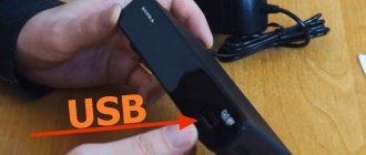
This console has quite miniature dimensions. The power supply is built-in, which is definitely a plus. The top cover of the case has a mirror glossy surface, which certainly looks elegant. This model does not have a display; the front panel contains: an LED status indicator, an IR receiver and a USB port.
