Software update via satellite
ATTENTION! Broadcasting software updates from satellite for Tricolor TV subscribers. Center" is temporarily suspended.
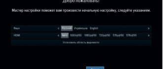
To update software via satellite, the receiver must be connected to a configured satellite dish.
PROCEDURE:
1.Unplug the receiver's power cord from the outlet, and then plug the receiver back into the power supply.
2. Switch the receiver to channel number 333 in the general list.
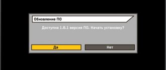
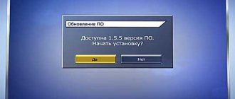
3. After a few seconds, the following message will appear on the screen indicating the need to update the receiver software:
When this message appears, select the “Yes” option and press the “OK” button on the remote control. 4. After agreeing to update the receiver software, service messages about the process of updating the receiver software will begin to appear on the screen. Updating the receiver software takes about five minutes.
5. Once the software update is complete, the receiver will reboot and enter channel viewing mode.
6. After the software update is completed, go to the “Status” menu and make sure that the receiver software version has changed to 1.35.324.
7. At this point, the receiver software update is completed, and the receiver is ready for further operation.
SatServis_
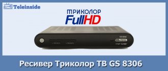
On April 1, 2013, a new receiver manufactured by GS became available to customers - satellite receiver for Tricolor - GS 9305 HD. This model cannot claim to be a new product in any way - because... is an analogue of a receiver GS 9303 HD, only with an added composite video output (“tulips” in other words). It’s good that, unlike the GS 8306 and GS 8307, in the receiver in question, the HDMI video output and the “tulip” can work simultaneously, which allows you to connect two TVs at the same time (although they will show the same thing). It is interesting to look at the markings on the printed circuit board of the GS 9305 HD receiver. The board is marked "GS 9303". That. the manufacturer just has to solder the video output tulips and now the new model of the receiver is ready for sale.That. The GS 9305 HD receiver is a complete analogue of the 9303 model on the same element base as its one, only with an added “tulip” type output. The processor used is the same STi7111, RAM is as before 256MB, assembled on Nanya chips of 128MB each. The receiver's power supply is located in the case; the existing USB connector can only be used for flashing the receiver.
In operation, the GS-9305 receiver performed well - channels are switched quickly, the picture appears immediately after switching, and is not assembled from scattered squares, as happens with the GS-8306. Not often, but still the receiver freezes and then you have to turn it off and on again to continue watching. This receiver model allows you to receive and view about 150 channels of standard quality (SD) and about 27 channels of HD quality.
The function of working with discs has been returned to the 9305 HD model, which means that now, in addition to tricolor channels, you can register channels from another satellite. But since there is no CI in the receiver, only open, unencrypted channels can be viewed from the additional antenna. The function of editing the channel list has also been returned. Many tricolor TV users complained about its absence in other models.
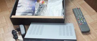
Receiver GS 9305 HD - equipment
The GS 9305 HD receiver comes in colorful packaging. In addition to the receiver itself, the box contains:
- two AAA batteries for the remote control. Often they have to be replaced immediately with new ones.
- remote control
- receiver manual in Russian
- Tricolor subscriber manual in Russian
- Maximum HD card with annual subscription - 1 pc.
- tulip cord (“3RCA-3RCA”)
- HDMI-HDMI cable
- warranty conditions and warranty card for the receiver
| click - to increase image size | ||
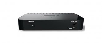
Receiver GS 9305 HD - rear panel
The receiver's connectors are necessary and sufficient. All that is there is an LNB input and loop output, HDMI, tulip (RCA) and optical output, as well as a USB connector used only for flashing. Unlike the gs-8304 and gs-8302 models, the receiver also has a power switch on the back. The optical output will allow you to connect the receiver to a home theater system and get higher quality sound than when connecting the receiver directly to the TV via the HDMI output.
| click - to increase image size |
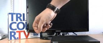
Receiver GS 9305 HD - front panel
The front panel of the receiver is a complete analogue of the 9303 HD model. In total, there are 4 buttons on it - power on/sleep mode, navigation buttons up/down and a button for switching from TV channels to radio and back. Moreover, the last three buttons are hidden under the cover that covers the card reader - so initially they are not replacements for the user. When the receiver is turned on, the “POWER” button lights up green and the display shows the current channel number; when it’s turned off, “POWER” lights up orange and the display shows the current time. The receiver display is only five-segment. But this has always been the case on tricolor receivers. So you won’t see a lot of technical information on it.
| click - to increase image size |
| Specification of the receiver GS 9305 HD | ||
| Main processor | : | ST7111 |
| FLASH memory | : | 32 MB |
| RAM | : | 256 MB, DDR2 |
| Graphical interface | : | 256 colors, full color |
| Frequency range | : | 950 MHz - 2150 MHz |
| Input impedance | : | 75 Ohm |
| Input level | : | -65 .. -25 dBm |
| Converter power supply and polarization | : | Vertical polarization: +14 ± 0.5 V Horizontal polarization: +18 ± 0.5 V Current: 500 mA max., overload protection |
| Range Switching Control | : | 22 kHz |
| Modulation type | : | DVB-S: QPSK and DVB-S2: QPSK, 8PSK |
| Input flow rate | : | 2 – 45 Msym/s for DVB-S, at least 30 Msym/s for DVB-S2 |
| FEC decoder | : | QPSK: 1/2, 3/5, 2/3, 3/4, 4/5, 5/6,7/8, 8/9, 8/10 8PSK: 3/5, 2/3, 3/4 , 5/6, 8/9, 9/10 |
| Supported channel search types | : | Network, manual |
| Teletext | : | VBI (ETS300472) and DVB |
| Subtitles | : | DVB |
| Timer | : | Eat |
| Menu languages | : | Russian English |
| Electronic guide | : | Eat. ISO-8859-5 standard |
| Decodable formats | : | MPEG-4 AVC: H.264 [email protected] , [email protected] , [email protected] |
| Managing external devices | : | No |
| Video resolution | : | up to 1920x1080p |
| Audio Decoding | : | MPEG/MusiCam Layer 1.2 |
| Audio mode | : | mono/stereo |
| Input Connectors | : | IEC 169-24 |
| Output connectors | : | — |
| Interface connectors | : | USB |
| Built-in conditional access system | : | DRE Crypt versions 1, 2 and 3 |
| Smart card slot | : | Eat |
| DVB Common Interface | : | No |
| Input voltage | : | 220 (+22/-33) V, 50 Hz |
| Power consumption | : | no more than 25 W |
| Dimensions (mm) | : | 250?180?38 |
| Net weight) | : | 1 kg |
| Working temperature | : | 5°C to 45°C |
| Control buttons | : | Standby, TV/Radio, Channel ^/Ў |
| Indication | : | Seven-segment 4-digit display. Special symbols for indicating signal reception, TV/Radio mode, StandBy |
| Attention! The characteristics, delivery set and appearance of the described device may differ from those indicated or may be changed by the manufacturer without being reflected in the SatSERVIS catalogue. When purchasing a device, check the specifications with the seller. | ||
Connections, 1 TV connection
Page 10
- Image
- Text
2. Connections
2.1 Connecting to TV
10
Connect 2 RCA connectors (red
• and white) 3RCA/3RCA cable to the corresponding color audio outputs on the digital receiver. Connect the 2 RCA connectors on the other end of the cable to the corresponding color audio inputs on your TV.
Connect the third connector (yellow)
• cable to the VIDEO output of the receiver, and the connector at the other end of the cable to the composite video input of your TV. If your TV does not have 3RCA sockets, but is equipped only with a SCART connector, then you will need a special SCART-3RCA adapter.
Connect the coaxial cable from the antenna to the LNB IN jack on the receiver.
•
Connect the 3 RCA cable connectors
• for 3RCA/3RCA to the corresponding VIDEO colors of the receiver, and the connectors on the other end of the cable to the component video input of your TV. If your TV does not have 3RCA sockets, but is equipped only with a SCART connector, then you will need a special SCART-3RCA adapter.
Connect 2 RCA connectors (red and
• white) 2RCA/2RCA cable to the corresponding color audio outputs on the receiver. Connect the 2 RCA connectors on the other end of the cable to the corresponding color audio inputs on your TV.
Connect the coaxial cable from the antenna to the LNB IN jack on the receiver.
•
Connect the HDMI cable connector to
• HDMI output of the receiver, and the connector on the other end of the cable - to the HDMI input of your TV.
Connect the coaxial cable from
• antennas to the LNB IN socket on the receiver.
2.1.1 Connection via Composite Video Output (CVBS)
2.1.2 Connection via component video output (YPrPb)
2.1.3 Connection via HDMI
Comments
Select → I found the instructions for my satellite here! #manualza
- Click →
Here at my grandfather’s barn, I found an old military brochure, produced in 1976: “Instructions for packing a parachute, second edition, supplemented and corrected.”
Manualza!manualza.ru
Still not with us?
Before use
Page 5
- Image
- Text
5
1. BEFORE STARTING OPERATION
1.1 Safety regulations
This receiver is manufactured in compliance with international safety standards. Please read the safety instructions carefully before use.
1. POWER SUPPLY
From an alternating current network with a frequency of 50/60 Hz and a voltage of 110-240V.
Connect the receiver only to a power supply with the voltage indicated on the label. If you are not sure what the power supply standard is in your home, contact your local electric company. 2. OVERLOADING
Do not overload outlets, extension cords or adapters as this may cause fire or electric shock.
3. LIQUIDS
The receiver should not be exposed to liquids, including splashing or dripping.
Do not place objects filled with liquids, such as vases, on it. 4. CLEANING
Disconnect the receiver from the power supply before cleaning.
Use a soft damp cloth for cleaning, do not use solvents. 5. VENTILATION
The ventilation holes on the top of the machine must be open to allow free air circulation.
Do not install the receiver on upholstered furniture, carpets, sofas, beds, or similar surfaces. Do not place other electronic components on the receiver. When installing the receiver on bookshelves or cabinets, ensure proper ventilation is provided and the manufacturer's installation instructions are followed. 6. MODULES
Do not use unsupported modules, they may seriously damage the receiver.
7. CONNECTING THE ANTENNA AND TV CABLE
Plug the power cords into outlets only after all components have been connected.
Disconnect the receiver from the power supply when connecting any cables, TV or other equipment to it and disconnecting all of the above components from it. 8. LOCATION
Install the receiver indoors, avoiding exposure to sunlight and rain.
Do not install it near heat sources or heaters. Make sure that the receiver is located no closer than 10 cm from sources of electromagnetic radiation - televisions, VCRs, etc. Do not install the receiver on unstable surfaces where it could fall. If it falls, it can cause serious physical damage to both a child and an adult, as well as malfunction. 9. THUNDERSTORMS AND LONG BREAK IN USE
Disconnect the receiver from the power supply during a thunderstorm or during long breaks in use.
These steps will help prevent damage to the receiver from lightning and power outages. 10. FOREIGN OBJECTS
Do not place foreign objects into the openings of the receiver, as this may cause damage to individual parts or electric shock.
Antenna assembly
- Assemble the antenna according to the instruction manual.
- Attach the antenna bracket to the wall. Fastening elements (anchor bolts, studs, nuts, screws, etc.) are selected depending on the wind load and the material of the wall on which the antenna is mounted.
- Install the converter in the holder with the connector facing down so that precipitation does not get inside the converter.
- Connect the cable to the converter using the F connector. To do this you need:
- Remove the top insulation of the cable by 15 mm without damaging the shielding braid.
- Place the braided shielding along the cable.
- Carefully place the foil along the braided shielding.
- Remove 10mm of internal insulation.
- Screw the connector until it stops.
- “Bite off” the central conductor so that it does not protrude beyond the connector by more than 2 mm.
- Secure the cable to the converter holder arc with plastic ties or insulating tape.
- Seal the entire length of the F-connector with heat shrink tubing or 2 layers of electrical tape, and apply an even layer of silicone sealant to the electrical tape.
- Install the antenna onto the bracket. Tighten the adjusting nuts so that you can move the antenna in the vertical and horizontal planes with some effort.
- Secure the cable to the antenna bracket with plastic ties or electrical tape. Leave a 1m cable reserve near the antenna, also securing it to the bracket.
Before use
Page 9
- Image
- Text
9
1.5 Remote control
1. BEFORE STARTING OPERATION
1.5 Remote control
15. PVR button block
Buttons for controlling recording and playback of previously recorded programs.
Not used in the basic configuration. 16. Button block
Buttons are not used in the basic software configuration.
At the operator's request, additional functions can be assigned to these buttons. 17. MENU
Calls up the Main Menu.
In menu mode, used to exit the menu and return to channel viewing. 18. VOL+/VOL-
Used to adjust the volume level.
VOL+ increases the volume level, VOL- decreases the volume level. 19. REC LIST
Opens the list of recorded programs.
The button is not used in the basic configuration. 20. Button
Changes the HD video output conversion mode (same as Button #).
21. BLUE button
Calls up lists of favorite channels.
22. YELLOW button
Calls up the menu for working with teletext and subtitles.
23. EXIT
Used to interrupt/cancel operations, to go to the previous menu screen, to exit the Main Menu.
24. OK
When watching a channel, calls up the channel list.
In other cases, it is used to select menu items or confirm input. 25. HELP
Calls up the Help menu, which contains explanatory information about the purpose of the receiver menu items.
26. # button
Changes the HD video output conversion mode.
27. TV/RADIO
Used to switch between TV and Radio reception modes.
The design of the remote control is subject to change without prior notice.
NOTE!