TV tuner
I have long wanted to make a TV tuner , even when I just entered technical school. The idea was to make a small attachment for the monitor, turning it into a full-fledged TV. The first experiment was something ugly and bulky made from 2-UPIMCT TV blocks with SKV-1, but still, this thing tried to catch some channels, then a prototype from 3-USTST blocks, even with a remote control. But again, it’s not the same.
About half a year ago I started designing a new TV tuner using modern elements. I took as a basis an all-wave tuner from Selteka - KS-H-146EA with i2c bus control. For the radio channel I used a simple solution on the TDA9800. Tuner control using the ATMEGA-8 microcontroller.
Actually, the project was started to evaluate our own strengths in creating a tuner from scratch, writing a control program in C, and familiarizing ourselves with the algorithm for controlling an all-wave tuner via a digital bus. Honestly, I figured out all the points and the TV tuner even worked, but tragically the flash drive that contained the entire project, the source code of the program, circuit diagrams, a drawing of the printed circuit board, everything disappeared! All that's left is the tuner itself and some sketches. Therefore, this article is more like a record of a successful but unfinished project that is unlikely to be completed to the end. But there are plans to design a more advanced TV tuner , but unfortunately, almost again “from scratch”, except that experience has already been gained.
The TV tuner consists of 4 main elements. The tuner itself, the radio channel, the control and display unit, and from the DC-DC converter are 5-33 volts. It’s inconvenient to explain with fingers, so I spent one of the evenings and restored the circuit diagram.
It was the KS-H-146 that attracted my attention because it is quite common, a datasheet for it was easily found (for the TDA6508 frequency synthesizer), that it has a built-in weak signal amplifier (Weak signal booster), supports the Russian TV standard. And by the way, the letters EA indicate the presence of an asymmetric IF output. When accessing the tuner programmatically, do not forget about the AS (Adress Select) pin, it is this that sets the configuration.
The radio channel on the TDA9800, I didn’t specifically choose it, since the project rather has the status of a prototype - I was looking for something simple from what was available. And this particular radio channel from an old VCR was at hand. After rummaging through the datasheet a bit, I settled on this diagram. Actually, it fulfills its function; in theory, you can use any other.
DC-DC converter. Since the entire TV tuner is powered from a voltage source of only 5 volts, it was necessary to find somewhere a voltage of 33 volts to power the varicaps in the selector. It seemed to me to be a very good solution to assemble a boost PWM converter on the MC34063 chip. The converter is quite small in size, the microcircuit is cheap, and there are a minimum of attachments. When calculating, I tried to get closer to the standard values so that I didn’t have to wind the coil. In reality, I set the inductor to 560 µH. You can take any diode for a suitable voltage.
Well, a microcontroller with an LCD display, buttons and external flash memory. Since this is a prototype, I didn’t want to bother with displaying information on the monitor screen, so I installed a regular two-line LCD display. The program was also lost along with the rest of the information, I no longer have the desire to restore it, but the source code of the firmware from the very beginning of construction remains. Actually, there is the main function of initializing the tuner and sending it a command to set a given frequency. Not quite a working option, but it might work for a start; by the way, I borrowed the function that sets the frequency for the tuner from the R-45 receiver project.
I downloaded the firmware from the prototype and put it at the end of the article. What I managed to implement in it: - frequency tuning with a given step (up and down) - setting the frequency tuning step - saving channels in external flash memory (operability has not been fully tested)
— activated the internal ADC for analyzing the AGC voltage (for automatic tuning and scanning)
In fact, the selector synthesizer is very simple to work with, all control is carried out using one function.
The data packet sent to the selector consists of 5 bytes. The first byte is the address, the second and third are the high and low bytes of the frequency, the fourth byte is the gain flag, and the fifth is the range.
The first byte is the Address. In my connection option, the AS (address select) pin of the tuner is set to log.0, and the address for accessing the selector via i2c will be 0xC0 (11000000).
The second and third bytes are the high and low bytes of the frequency. Calculated using the formula (Fchannel + Fpc)/step. Fchannel - channel frequency, i.e. which we are tuning into. Ff is the frequency of the inverter (38900) and the tuning step is 50. i.e. we get - (F+38900)/50. We divide the result into two bytes using the functions: (uint8_t)((w >>
& 0x00ff) for the high byte and (uint8_t)((w >> 0) & 0x00ff) for the low byte. Example: for a frequency of 464.5 MHz, the tuner will receive the high byte 0x27 and the low byte - 0x54, for a frequency of 107.7 MHz - 0x0B and 0x74.
The fourth byte is the gain flag. If the gain needs to be turned on, we send byte 0x89, if turned off - 0x88.
The fifth and last byte is the range byte. Everything is simple here, if this is the first range “LB (low band)”, we send 0x01, if the second is “MB (middle band)” we send 0x02, for the third range “HB (high band)” we send 0x0C. The range is calculated immediately after setting the frequency. By default, “LB” is set, then the frequency is checked by a condition and if it exceeds 155 MHz, the byte is changed to “MB”, then we check again by the condition and if it exceeds 440 MHz, we change the byte to “HB”. Example: for a frequency of 464.5 MHz we must send byte 0x0C, and for a frequency of 107.7 MHz we must send byte 0x01.
As a result, a packet of bytes to set the frequency to 464.5 MHz with amplification will look like this - 0xC0 0x27 0x54 0x89 0x0C, and to set the frequency to 107.7 MHz without signal amplification - 0xC0 0x0B 0x74 0x 88 0×01.
Otherwise, the program will be limited only by the flight of your imagination, and the technical parameters of the microcontroller and tuner.
Schematic diagram of a TV tuner. TV tuner circuit board. TV tuner source files (Code Vision AVR). TV tuner firmware (HEX + EEPROM + fuses) (test Beta version).
Feasibility of repair
It is also not recommended to undertake repairs to a digital receiver if it is a complex universal set-top box. Such devices include several decoders, support different television formats, and also have additional inputs and slots. When it comes to such a device, it is safer to take it to a service center for repair.
If the fault is minor and can be fixed without much effort and with your own hands, then you can disassemble the case and find the cause of the breakdown.
Where to get spare parts and parts
If you have time for repairs, it is better not to purchase anything first, but to inspect the faulty receiver. When the breakdown is found, you can proceed to purchasing spare parts and components for repair and replacement.
If we are talking about replacing a specific board or element (connector, lamp, chip, etc.), it is more profitable to buy it. To do this, you can contact the radio market. If there is nothing there, then there will definitely be a part in any television equipment workshop.
When minor system breakdowns occur (the case is cracked, contacts are burnt out, the button is faulty), the winning option would be to purchase a faulty donor to repair the main one.
A non-working analogue can be found in advertisements for 10% - 20% of the price of the receiver itself. At the same time, it is important to take into account what kind of breakdowns are observed in the device so that the necessary elements are in good working order.
A digital DVB-T2 set-top box for disassembly can be bought at any radio market or through advertisements
Receiver configuration
Before repairing, you need to know what the DVB-T2 receiver consists of. It is actually a complex device that includes many elements.
But in this case, only a few of them may be of interest:
- Inputs. This is an RF IN connector and a socket for network connection.
- A/V output. Connectors for connecting a wire from a TV, through which image and sound are output in the usual form.
- Decoder. Binary code recognition device.
- Voltage transformer . Changes the mains current to the value required to power the receiver.
- Built-in memory. A small chip on a board on which the receiver software and TV channel settings are stored.
The remaining hardware or software components are not interesting for the reason that without professional skills it is impossible to fix their malfunction.
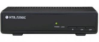
Working indicator lights on the digital receiver when power is applied perfectly indicate the correct current supply
Nutrition
First you need to check it yourself, for which it is enough to connect any small light bulb (for example, from a flashlight) to the contacts via wires. If it lights up, the indicator is faulty, otherwise you need to check the power supply.
If the methods described above do not help solve the problem, incorrect current supply can only be associated with damage to the device board. In most cases, this is the destruction of contacts associated with overheating or short circuit. It is better to immediately take the expensive DVB-T2 set-top box to a service center for repairs, and replace the cheap receiver.
Inner memory
Often, minor glitches occur due to working under outdated software that is no longer supported by the developer.
Inputs and outputs
Malfunctions with connectors often lead to low quality or even no images at all. In this case, no visible software failures occur. Unlike most other elements of the console, the connectors are easy to replace and solder.
First, the RF IN input must be checked, because even the slightest disconnection from the board will lead to a lot of noise in the first place. When using an old TV with a wobbly socket, severe interference could be observed.
Only with the reception of digital broadcasting the situation is even worse for two reasons:
- VHF radiation has shorter waves compared to the DM range. When they become noisy, they fade faster and the signal quality drops even more.
- If the quality is low, you won’t be able to watch digital TV with interference like the analogue TV in the country. The problem is that to display an image you need to obtain the full amount of data and decrypt it. If the reception level is low, some of the data is lost and decryption is impossible.
With outputs it is simpler and all you need to do is have a contact with the board. However, if you encounter a “wobbly” output, it is better to solder it securely. Sooner or later, such sockets move away under the weight of the plug.
According to the standard for digital TV, there are only 3 RCA audio-video outputs (tulip).
If there is a “silent movie”, the white or red output is faulty. When the situation is reversed, there is only sound - a yellow connector.
An expensive receiver may have a Scart or HDMI connector instead of RCA. This is only one output, but with a large number of contacts that can only be soldered with professional equipment.
Decoder
If the digital television set-top box is fully operational, but only digital channels are not shown, the problem lies in the lack of binary code recognition. It is responsible for the Digital DVB-T2 decoder, which may be faulty or not perform its function due to the lack of a command to do so.
To find an error in software operation, you need to connect the decoder contacts via wires to the UART diagnostic port. The device can be purchased at any radio market (100 - 200 rubles).
Its USB input must be inserted into the computer and the HyperTerminal utility launched.
In the window that opens, enter the following characteristics:
- speed 115200 bps,
- number of bits – 8,
- parity - no,
- stop bit - 1.
After this, the power of the DVB-T2 receiver is turned on and reading starts.
As a result, you may see the following messages:
- Demod IIC read error/Demod IIC write error . The decoder cannot read or process the incoming signal. This indicates that the device itself is damaged and will need to be replaced.
- Error decompressing file. The file responsible for controlling digital signal processing is missing. It is necessary to perform firmware update of the equipment.
Replacing the decoder is justified only for more or less worthwhile DVB-T2 set-top boxes. Repairing a cheap model will cost more than buying a new receiver.
Voltage converters
If, after turning on the set-top box, a very weak startup sound is heard and abruptly stops, the processor is receiving a current different from what was required before the repair. Here you need to check the voltage on the inductor or capacitor from each converter board. The nominal value for a specific board should be 3.3, 1.8, 1.2 V respectively.