I think many of you are interested in learning about the principle on which an LED TV works and what components it consists of. Nowadays, when creating modern television models, the relatively new LED technology is actively used, which rightfully occupies an honorable place in the market today. In this publication, we will try to examine in detail the design of an LED TV by looking inside it. Let's try to figure out what the peculiarity of the structure is and what the manufacturers are hiding behind such a popular abbreviation, which arouses genuine interest among consumers in such models.
The very definition of LED (Light-emitting diode) means LED. This term was first introduced by Samsung in 2007 to promote its new line of TVs. This was not a marketing ploy, but rather a breakthrough in the IT field, since the lighting was no longer carried out with lamps, but with LEDs. Recently, quite often such LED panels are found on city streets, near and inside stadiums, open concerts and presentations. The image of such a huge TV is grainy, which is due to the size of the LEDs - unfortunately, it is not yet possible to bring them closer in size, for example, to a pixel for these purposes.
However, over a long distance, the grain is not noticeable, and the unique design makes it possible to assemble truly large screens. But this is only a small part of the information, and all the interesting things are behind the scenes. The fact is that LED TVs, unlike large outdoor TV panels, are of a completely different design and LEDs are used differently in them. In fact, in such a TV, LEDs play the role of illuminating the liquid crystal matrix, and do not “display” the image on the screen. But the mentioned principle laid the foundation for OLED technology.
The type of matrix backlight for the TV is LED.
Such models with a liquid crystal screen, unlike LCD products that use fluorescent or fluorescent lamps (HCFL - hot cathode and CCFL - cold cathode), are illuminated by light-emitting diodes. A new type of backlight for the LCD matrix compared to LCD made it possible to reduce the thickness of the structure and increase image quality. The main technical points that it is advisable to pay attention to before buying a TV are described in the first and second publications.
There are several types of LED backlighting of the liquid crystal matrix: carpet or otherwise, direct (Direct-LED) and edge, which is also called edge (Edge-LED).
- Direct-LED (Full-LED). The carpet type of lighting involves the placement of light-emitting diodes over the entire area of the matrix. It is this arrangement of LEDs that allows for uniform illumination and maximum quality images. Direct-LED TVs have rich brightness levels and good contrast.
- Edge-LED. Edge lighting has positive and negative sides. Why? The fact is that here light-emitting diodes are located along the edges or sides, and sometimes along the entire perimeter of the matrix. The emitting light from the diodes hits a specialized distributor, and then onto the diffuser, and only then onto the screen. Unfortunately, this arrangement of LEDs does not provide full local dimming in certain areas of the screen and a good contrast transition.
Of course, the end design allows you to reduce the thickness of the entire TV, but this has its consequences. Firstly, due to the placement of LEDs around the perimeter rather than across the area, fewer diodes are used, which means the matrix is not illuminated properly. Secondly, getting good light distribution is quite difficult in a thinner body. As a result, the thin diffuser does not cope with the task assigned to it properly and light spots (flares) may form in the dark areas of the screen at the output.
In turn, “harmless” light spots can interfere with the comfortable perception of video from the TV screen. It should be said that engineering solutions are gradually bringing it to a good level.
Article Archives
Defects in CRT TV picture tubes Some defects can be easily eliminated by demagnetizing the picture tube with a special demagnetization loop or a simple demagnetization choke. Their main use is in horizontal scanning units for generating high voltage at the anode of the kinescope and secondary voltages: powering the filament circuits of the kinescope, accelerating voltage, powering the video amplifier board.
When a command is received from the remote control to the IR sensor, and then from the IR sensor, the detected command code is sent to the input of the video processor, or when a command is received from the keyboard located on the front panel of the TV to the input of the video processor, a power-on command is sent from the video processor via the I2C bus.
LCD TV Here the circuit has changed even more, since digital signal processing is mainly used. The rate of sound rise during recovery can be changed by selecting capacitor C5.
Mega selection of firmware A huge selection of firmware for almost all TV models, sorted by company and individual TV model. The device operates in the infrared range.
How to connect an antenna to a TV In order for a working TV to show TV channels perfectly, and not just snow or a blue background, you need to correctly connect your TV to the antenna or cable TV. Colored spots have appeared on the kinescope.
For example, my wife is watching a stupid TV series, and we want to watch football.
The cascade on transistor VT1, which is a half-wave detector, monitors signal changes, and in the absence of advertising it is open. Learning to read diagrams
More on the topic: Estimate for installation of electrical wiring
The difference between static and dynamic backlighting.
All of the above can be attributed to static backlighting. As you understand, here the diodes emit light constantly and there can be no talk of any control. Dynamic backlighting, on the other hand, makes it possible to control the light on individual areas of the screen. This is achieved by dividing the matrix into separately connected groups, which in turn made it possible to control the brightness in a certain area of the screen depending on the scene being played back. This approach generally resulted in clear color reproduction and relatively deep blacks with local dimming, reduced power consumption and increased environmental friendliness.
In turn, TVs can also have dynamic RGB backlighting in the carpet and edge type of arrangement of light-emitting diodes. Here, instead of just “white” LEDs, red, green and blue LEDs are used. By the way, a fourth white light-emitting diode is sometimes added to them, which ultimately gives a pure white color on the TV screen. Light-emitting diodes can be located either individually or in groups consisting of different base colors.
Such a matrix with carpet backlighting is capable of reproducing images in different areas with the required degree of brightness and color gamut. As a result, the image turns out to be of high quality and rich in terms of brightness. The edge matrix with RGB backlighting is thinner, but it is unable to convey the effects of color local dimming or the color gamut as a whole at the same level. Due to the location of the LEDs, the matrix is completely illuminated along its entire width and length. However, such a TV also decently conveys the entire overall spectrum of colors.
For what?
Every person reading this article is probably already wondering with surprise about who and for what purposes might need to make a TV from a monitor with their own hands. After all, the era of shortages is irrevocably gone; in any city there are at least a dozen stores selling all kinds of electronics for every color and taste. Why suffer and make great efforts to make one thing, and one of dubious quality, out of two individually good things?
There are several fairly logical answers to questions like these.
First of all, it's just interesting. Despite the fact that the need to do anything with your own hands has disappeared in our time, there are still many people who are nostalgic for the times of the Soviet Union, when they had to solder, tin and saw out almost everything themselves - from electric guitars to speakers. There is a bag of parts, there is a set of tools. That's it, then think and do it yourself.
Secondly, not everyone has the opportunity to purchase a new expensive monitor for watching TV. But in the closet, perhaps, there is an old computer screen and several circuit boards that will allow you to make a pretty good TV with your own hands.
Thirdly, such operations significantly develop the brain and help simply kill time profitably. The result is obvious: an interesting homemade product is hanging in the garage, and the time is spent with interest, and I seem to have learned something for myself, and even got a lot of pleasure from the work!
Advantages of homemade products
The positive aspects of such a design include significant ease of manufacture, greater durability, and ease of use. It will not be difficult for an experienced user of a personal computer to master the operation of a self-made TV. It should also be noted that the device will be relatively cheap compared to real, factory-made TVs. The “advantages” include the fact that the entire structure is assembled from parts already existing in the house without additional costs.
Pay
Working with wires, parts and boards usually requires extensive knowledge of radio electronics, but in the case of modern monitors the whole process comes down to just soldering incoming contacts, which must be disconnected from the connection points with the computer wires and output to a device that provides a television signal. Such a device can be a tuner or a special set-top box that gives access to the broadcast network.
LCD monitor
Modern man increasingly feels himself to be part of the future, part of constantly moving progress, so those things that until recently seemed to him new products and a “miracle of technology” no longer have any meaning today. This fate befell vinyl records, floppy disks, CDs and DVDs. And now the time has come for desktop computers. And this is not surprising. Who needs old bulky personal computers when so many different companies produce ultra-new, thin and light laptops, tablets and smartphones with wide screens, as well as laptops and netbooks.
Most advanced users have long been part of the “mobile community”, having switched from computers to new and modern gadgets. However, taking into account the mentality of the common people, it is safe to say that old PCs were not only not mercilessly thrown into the trash, but, most likely, were carefully cleaned, packaged, and are now stored in storage rooms.
You can make an excellent TV from an old monitor with your own hands, which, if all the necessary work is done efficiently, can last for many, many years.
However, before you start creating a new device from several old ones, you need to purchase a few more parts:
- TV tuner;
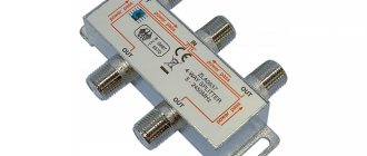
- splitter, as well as a cord for connecting multi-channel digital television;
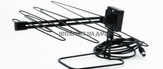
- antenna;
- cable for antenna installation.
After purchasing all the above parts, you just need to connect all the devices together. Since the connectors in them are different, it is simply impossible to make a mistake during installation. If the TV does not turn on, repairing it yourself will be much cheaper and easier, since spare parts for a computer are much easier to find on sale than outdated mechanisms for a TV set. This will also significantly affect the popularity of the homemade device among low-income people.
Menu
Introduction
It is assumed that the main means of receiving digital television in Russia will be set-top boxes for analog televisions, and, to a lesser extent, televisions with built-in DVB-T receivers.
Set-top boxes based on imported components are already produced by some domestic enterprises. One of the largest manufacturers of components for digital TVs and set-top boxes is the Japanese corporation Renesas Electronics. In April 2010, NEC Electronics Corporation and Renesas Technology completed their merger, forming the new company Renesas Electronic Corporation, which became the third largest semiconductor company in the world, according to Gartner.
The parent company, Nippon Electric Company, Limited (NEC), was founded in 1899 as a joint venture with the Western Electric Company, co-founded on the Japanese side by Thomas Edison's student Kunihiko Iwadare (Fig. 1) [1]. The company produced telephone sets and switching equipment. NEC Electronics Inc. was created on the basis of the American branch of the company to produce semiconductor devices for the US market, and in 1984 a plant was opened in Roseville, California. In 2002, NEC Electronics Corporation was separated from its parent company and focused on the production of semiconductor devices and chips.
rice. 1. Kunihiko Iwadare
Renesas Technology was founded by Hitachi and Mitsubishi Electric in 2002 to organize the production of microprocessors and semiconductor devices. In the new company Renesas Electronics Corporation have shares: NEC Corporation (33.97%), Hitachi Ltd. (30.62%), Mitsubishi Electric (25.6%) and Japan Trust Services Bank, Ltd. (1.49%). On July 6, 2010, Renesas Electronics reached an agreement to purchase Nokia's wireless modem business. The company's headquarters is located in Tokyo (Fig. 2), the number of employees is 47,000 people, the president is Yasushi Akao, the chairman of the board of directors is Junshi Yamaguchi (data as of April 2010) [2].
rice. 2. Renesas Electronics headquarters in Tokyo
Product structure of Renesas Electronics Corporation in 2010: microcontrollers and microprocessors (16 groups); ASSP chips (5 groups); discrete semiconductor devices (Power MOSFET, IGBT, transistors, diodes, high-frequency and microwave devices, optoelectronic devices). The ASSP group includes LSIs for video and audio applications developed by NEC Electronics - digital LSIs of the “system on a chip” type (Digital Audio-visual SoCs, Former NEC Electronics), as well as chips for video and audio applications from Renesas Technology (Former Renesas Technology) [ 3].
Components for digital television
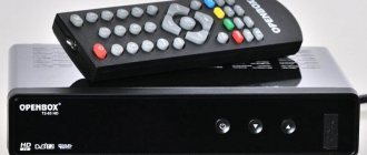
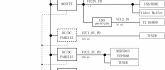
The 2010 Renesas Electronics catalog offers most of the components needed to build digital televisions and set top boxes for receiving terrestrial digital television, including DVB-T. Including their main components: LSI digital demodulators CODFM and MPEG-2, MPEG-4 decoders of the EMMA series. In Fig. Figure 3 shows a variant of the block diagram of the company's digital set-top box (the appearance of the set-top box is shown in Fig. 4), and in Fig. 5 - a variant of the block diagram of a digital TV. In addition, components are produced for power management systems for set-top boxes and TVs and for controlling LCD TV displays.
rice. 3. Block diagram of a digital set-top box
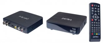
rice. 4. Appearance of the digital set-top box
rice. 5. Block diagram of digital TV
The company produces MPEG-2, MPEG-4 decoders of the EMMA series of the following types (the appearance of the chips is shown in Fig. 6):
- EMMA3TJ/TS/TH/TL2/TL/SV - for digital TVs MPEG-4 (H264);
- EMMA2TS/TL/TH/H/SL/SV - for MPEG-2 digital TVs;
- EMMA3TS/SL, EMMA3SL/P, SL/L, SL/LP, SL/HD, SL/SD, EMMA3SV - for MPEG-4 digital set-top boxes (H264);
- EMMA2TS/SE, EMMA2SE/P, EMMA2+, EMMA 2+S, EMMA2SL/S, SL/P, SV, LL, L - for MPEG-2 digital set-top boxes.
rice. 6. Appearance of EMMA chips
In addition, MPEG codecs and decoders for Blue Ray and DVD players and recorders, MPEG encoders, channel decoders, character generator chips (OSD), digital selectors for brightness and color signals, and video decoders are produced. The developer of most LSI EMMA chips is NEC Electronics; currently the EMMA logo is a registered trademark of Renesas Electronics Corporation in Asia, the USA and several European countries. In April 2009, the number of EMMA chips produced exceeded 100 million.
Before considering the features of EMMA decoders, let us briefly dwell on the features of compression standards. The standardization process in the field of digital video compression is carried out under the leadership of two organizations: ISO (International Standards Organization) and ITU (International Telecommunications Union). Most video compression standards are based on the principles of the ITU-T H.261 standard. In 1995, the ITU-T H.263 standard was completed, after which the Video Coding Expert Group (VCEG) began work on a long-term project to develop a standard for low bit-rate video compression. The work culminated in the creation of a draft version of the ITU-T H.26L standard.
In parallel with these works, the ISO Motion Picture Expert Group (MPEG) first introduced the MPEG-1 standard, and then MPEG-2, already suitable for high-quality broadcasting. Subsequently, the MPEG-2 standard was improved many times and came to the limit of its capabilities.
In 2001, the Joint Video Team (JVT) was created from MPEG and VCEG experts, whose task was to create two identical standards: ISO MPEG-4 Part 10 and ITU-T H.264. The newly created standard received the official name MPEG Advanced Video Coding (MPEG-4 AVC). The ITU-T H.264 and ISO/IEC MPEG-4 Part 10 standards are technically completely identical, the final draft of the first version of the standards was completed in 2003, its formal name is ISO/IEC 14496-10. The MPEG-4 AVC standard is also known by its former name ITU-T H.26L and by the name of its development team, JVT [4]. Other organizations, as well as individual companies, are also working on creating digital video compression standards; in particular, Microsoft Corporation created the WM9 standard.
Delivery of services in the DVB standard is carried out using the MPEG transport stream (TS), described by ISO/IEC 13818-1 or ITU-T Rec H222.0 standards. The MPEG transport stream may have the names MPEG-2 TS, MPEG TS, MPEG-2 Part 1. When used in digital television, its specification has been supplemented by the additions described in the ETSI EN 300468 standard and some others. In connection with the above, in relation to LSI EMMA, for simplicity of presentation, we will use the names MPEG-2 and MPEG-4 for video decoders and MPEG-2 TS for transport stream decoders and consider the features of some LSI EMMA in more detail.
EMMA2SE (µPD61140, µPD61141), EMMA2SE/P (µPD61142, µPD61143) - LSI chips for digital set-top boxes with a hard drive driver. The structure of the microcircuit is shown in Fig. 7, appearance - in Fig. 8. In addition to signal decoding, MPEG-2 VLSI provides digital video recorder (DVR) function and supports the operation of two tuners, EMMA2SE/P VLSI has additional functions to protect content from copying. It should be noted that the MPEG-2 standard has long been used for broadcasting in Russia (VolgaTelecom, etc.), however, for promising projects of the future domestic digital television, it is planned to use other compression standards, in particular MPEG-4.
rice. 7. EMMA2SE chip structure
rice. 8. Appearance of EMMA2SE chips
Main features and functionality of VLSI.
— Central processor:
- main processor (CPU): for RTOS/API/BIOS applications;
- On-chip MIPS32 4KEc core;
- performance 284 MIPS at 186 MHz;
- MIPS l and MIPS ll support;
- cache memory size: l-cache 8 KB, D-cache 8 KB;
- coprocessor: for decoding and processing signals;
- On-chip MIPS32 4KEm core;
- performance 284 MIPS at 186 MHz;
- Cache memory size: L-cache 8 KB, D-cache 8 KB, Scratch Pad 32 KB.
— Memory interfaces:
- RAM: unified RAM interface for central processor, MPEG-3 encoder, graphics, display, etc.;
- DDR interface, support for memory sizes of 16-128 MB;
- EEPROM: Supports NOR/NAND Flash ROM up to 64 MB (NOR Flash ROM).
— MPEG-2 TS transport stream processing unit:
- Hardware processing architecture;
- MPEG-2 TS transport stream interface: three outputs from two parallel inputs, two serial inputs, one playback input;
- maximum transport stream processing speed: 100 M6ot/s for each input, 180 Mbit/s for three inputs;
- general purpose filter 96 PID Filter;
- High Speed Data (HSD) support output port;
- MPEG-2 video decoder: support MPEG-2 MP@ML;
- audio channel controller: support MPEG-1/MPEG-2 Layer 1/2; support for digital outputs of left and right channels (DAO - Digital Audio Output L/R); SPDIF output;
- graphics - 2D BitBLT;
- display: 5 background layers (Background, BG), 2 video layers, 2 character generator layers (OSD).
— Video signal generator:
- NTSC/PAL encoder; support for subtitles (Close Caption), WSS, VPS; video signal identification, teletext;
- 6-channel video DAC for simultaneous generation of composite video signal (PCTS), Y/C signal and RGB/YCbCr signals;
- ITU-R BT.656 digital video output function.
- Peripherals:
- UART x2; Smart Card x2; I2C x2; serial clock interface (Clocked Serial I/F);
- timer: 2-system, WDT, RTC;
- two infrared receivers, an infrared blaster;
- General PIO.
— ATA interface: PIO mode, UDMA33, UDMA66.
- USB 2.0 host controller complies with the EHCI specification, transfer speed: high - 480 Mbit/s, maximum - 12 Mbit/s, low - 1.5 Mbit/s.
— PCI interface is compatible with PCI Rev2.2, bus clock speed 33 MHz, 32 bits.
— VLSI is made according to the technological process of 0.15 microns, supply voltage: 3.3; 2.5; 1.5 V. [5].
MPEG-4 Decoders
EMMA3SV (µPD61300, µPD61303) - high-performance single-chip VLSI for decoding digital television signals. The structure of the microcircuits is shown in Fig. 9. The microcircuits provide all the functions necessary for TV viewers and are designed for digital TVs and set-top boxes using the MPEG-4 standard, which is gaining popularity in Europe, Russia, India and Brazil. The chips can also be used in set-top boxes and televisions designed to receive IPTV signals.
rice. 9. EMMA3SV chip structure
Features and functionality of VLSI:
— High-performance central processor:
- MIPS32 24KEc CPU;
- MIPS470 performance at 327 MHz;
- cache: 16 KB instructions, 16 KB data.
— Memory interfaces:
- DDR2, 16 and 32 bit buses, total memory capacity 32-256 MB, bandwidth (Bandwidth) 2.6 Gbit/s;
- FLASH ROM, total memory capacity 64 MB with 8- and 16-bit buses.
— MPEG-2 TS (DVB) transport stream processor with 36 PID filters with four input ports provides processing of two serial and two parallel transport streams.
— The chip provides decoding of video signals in the following formats: MPEG-2 MP @ [email protected] HL, MPEG-4 (H.264/AVC HP @ L4.0, 3.2) and VC-1 AP @ L3, L2.
— The audio decoder provides decoding of MPEG1/2 L1/2, MPEG-4 AAC, MPEG-4 HE-AAC, DD, DD+, MP3, WMA signals. There is SPDIF output and 5.1 channel audio output interface.
- 2DBitBlt graphics, 6 layers, 256-level Alpha-blending Function.
— VLSI provides real-time image scaling in the range from 1/4 to 8 horizontally and vertically.
— Video signal generator: NTSC, PAL, SECAM, there are two DACs for receiving PCTS and Y/C signals.
— USB 2.0 interface, compatible with the EHCI specification, can operate in High, Full and Low modes.
— There is an integrated Ethernet MAC interface that complies with IEEE 802.3/3u/3x, ensuring compatibility with the RMll specification (10, 100 Mbit/s).
- Peripherals:
- 2-channel FUART interface, one UART channel;
- 2-channel interface for smart cards;
- 2-channel I2C interface;
- serial clock interface (Clocked Serial Interface);
- 2-channel IR interface, IR blaster;
- Watchdog Timer, real-time clock;
- 559-pin plastic BGA package [6].
EMMA3TH (MC-10153) is one of the latest devices presented by the new company Renesas Electronics Corporation (a brief description of VLSI was released in April 2010). It is a system on a chip. The VLSI block diagram is shown in Fig. 10. The chip provides decoding of high-definition broadcast television signals from DVB (used in Europe), ARIB (used in Japan) and ATSC (used in North America) and is intended for use in digital high-definition televisions.
rice. 10. EMMA3TH chip structure
Features:
- Multi-CPU system.
- Main CPU: VR5500-compatible SS1000 core (655 MIPS performance at 327.68 MHz).
- Secondary CPU: MIPS 4KEc core (393 MIPS performance at 327.68 MHz).
- Secondary CPU: MIPS 4KEm core (performance 196 MIPS @ 163.84 MHz).
- RAM: DDR2, 32 and 16 bits, up to 4.8 GB/s.
- The stream processor supports 4 transport streams, provides encryption/decryption of signals: AES, Multi2, DVB, DES, 3DES.
- Supports MPEG-2 TS, MPEG-2 PS, MPEG-1, DVB, ARIB, ATSC.
- Multi-system decoder of digital video signals of MPEG-1, MPEG-2, MPEG-4 AVC, VC-1 standards.
- Multi-system decoder of digital audio signals of MPEG BC, Dolby Digital, MPEG-2 AAC standards.
- MPEG-2 HE-AAC, Dolby Digital Plus.
- De-interlacer converter for HDTV support.
- 14-bit digital signal processor for image quality enhancement, providing adjustment of brightness, contrast, color saturation, 2D aperture, sharpness, white and black level, gamma correction, image format conversion and other functions.
- There are two LVDS outputs to support HDTV 1920Hx1080V, 60 Hz.
- Outputs NTSC, PAL, SECAM, Y/C and composite output.
- 4-channel high-speed ADC with quality up to 1080p and WUXGA.
- 3D combined analog video decoder (external signals are connected via SCART).
- HDMI receiver.
- Various external interfaces: Ethernet MAC, two USB 2.0, PCI, SmartCard, four UART, three I2C, CSI Host, CSI Target, GIO, GPIO and others.
- Supply voltages 3.3, 1.8 V (for external interfaces), 1.05 V (for internal logic, HDMI, PLL).
- System clock frequency 32.768 MHz.
- BGA package 35x35 mm, 933 pins with 1 mm pitch [7].
EMMA3TL2 (MC-10157) is a system-on-chip device developed by Renesas Electronics Corporation (VLSI brief released April 2010). The chip is also designed for high-definition TVs. Let us note the main features of the microcircuit that differ from EMMA3TH.
- Multiprocessor CPU system:
- main CPU: MIPS32 4KEC core (performance 500 DMIPS at 327 MHz);
- auxiliary CPU: MIPS32 4KEc core (performance 500 DMIPS at 327 MHz);
- additional CPU: MIPS32 4KEm core (performance 306 DMIPS at 200 MHz);
— RAM DDR2-800, 32 bits, up to 3.2 GB/s;
— support for DRM networks for streaming IP (Windows DRM, etc.);
- virtual surround sound;
— the video decoder additionally processes AVS, DivX-HD, MPEG-4 ASP formats;
- integrated Super Resolution Function;
- 15-bit digital signal processor to improve image quality;
— support for the “picture in picture” function (from a computer and composite input);
— input audio ADC with 6 in 1 switch and 4 stereo DAC;
— OneNAND interface;
— system clock frequency 48 MHz;
— BGA package 31×31 mm, 632 pins with a pitch of 1 mm [8].
Based on VLSI EMMA3SV it is possible to build advanced digital TVs and high-definition set-top boxes, and based on VLSI EMMA3TL2 - digital TVs (manufacturer's recommendation).
Literature
- Anderson J. Kunihiko Iwadare: Edison Apprentice and NEC Cofounder - https://ieeexplore.ieee.org/ stamp/stamp.jsp? arnumber=00916347
- https://ru.renesas.com/press/news/press_release01april2010.html
- https://www.renesas.com/prod/
- New generation of video compression: MPEG-4 AVC (based on materials from Scopus Network Technologies) // Magazine “625”. 2004. No. 3.
- EMMA2SE, EMMA2SE/P - https://www2.renesas. com/digital_av/en/mpegdec/d61140_d61142. html
- EMMA3SV - https://www2.renesas.com/digital_av/en/mpegdec/emma3sv.html
- EMMA3TH - https://www2.renesas.com/digital_av/en/mpegdec_tv/emma3th.html
- EMMA3TL2 - https://www2.renesas.com/digital_av/en/mpegdec_tv/emma3tl2.html
CRT monitors
All those who started using computers back in the era of their appearance remember the old “humpbacked” monitors with a convex screen. Most craftsmen who have dealt with these technical devices in one way or another claim that CRT monitors are not suitable for creating a TV on their basis. No, of course, something can be done, but due to the low performance characteristics of the monitor, the image quality will be extremely low, and significant problems with the video display speed may also arise.