The fleet of analogue TVs is rather reluctant to give way to digital equipment, gradually taking “second” places - in the kitchen, in offices, garage workshops, etc. At the same time, DVB-T2 set-top boxes are also carried. We have already managed to evaluate the advantages of the latter; some owners also appreciated the disadvantages - the rather low reliability of these devices. As a rule, one of the weakest points of this kind of equipment is the switching power supply - most cases of failure are associated precisely with a malfunction of the power supply, and a malfunction of the power supply can entail such serious consequences that repairing the device will be impossible. And yet, using the example of two digital TV set-top boxes, the possibility of repairing them independently will be considered here. The first device was TVK 3101. When turned on, the image had severe distortion and periodically disappeared completely. A few days later, the set-top box began to turn off a few seconds after the manufacturer's logo appeared on the screen.
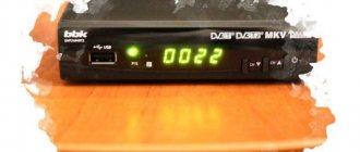
The second device is the Oriel 740 set-top box. This device did not respond to commands from the remote control, the indicator barely glowed red.
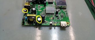
After opening the console cases, it turned out that in both cases the electrolytic capacitors of the secondary power filters were swollen.
It should be borne in mind that when working with the set-top box, special care should be taken - the primary power supply rectifier converts an alternating voltage of 220 volts into a constant voltage of about 300 volts, and this potential remains at the terminals of high-voltage electrolytic capacitors for some time after the power is removed - up to several tens of seconds . In the pictures they are located between the pulse transformers and the plugs of the power cords. Before working with the device board, these capacitors must be short-circuited through a resistor with a resistance of 51-62 kOhm.
Both faulty capacitors turned out to be almost the same - 1000 µF, 10 V. The picture shows one of them. The fact that its lid looks barely deformed should not give you the slightest confidence in the serviceability of the part - even if some part of the container has been preserved, such a part will have an increased leakage current, which is unacceptable. When replacing, you should select capacitors with the same operating voltage or with a slightly higher one, as in the picture - instead of a 10-volt part, a 16-volt part is shown, and with the same dimensions. Of course, faulty parts should be replaced with new ones, not used ones - otherwise the repair will soon have to be repeated.
After replacement, we turn on the set-top box - the indicator lights up brightly, the device responds to remote control commands, the image is stable. But the renovation is not finished yet...
There are traces of flux on the board - solder paste, rosin... Through such a coating, high-frequency currents can quite easily pass wherever they want. As a result, over time we may get an unstable image, noise, etc. troubles. Therefore, carefully wash the board with a cotton swab moistened with alcohol or acetone. After such cleaning, wipe the board with a dry cotton swab.
We install the board in place, check - it works.
Now we assemble the console completely and check its functionality again.
We check the second device in the same way - the device is working normally, the repair is completed.
In conclusion, I will add that the quality of the antenna amplifier power supply also greatly affects the operation of the set-top box. Thus, if the capacity of the filter capacitor is insufficient, signal loss is possible - there have been cases of complete loss of channels of the second multiplex. To recognize a malfunction of the antenna power supply, it is enough to replace it with a DC source of 9-12 volts (for example, a Krona battery or a battery from a computer uninterruptible power supply). If the reception quality improves, you should replace the antenna power supply with a known good one.
In the article, the author shares his experience of repairing a tuner for receiving terrestrial digital television programs. The troubleshooting technique he described is applicable to other electronic products, where one or more functional units are powered by a voltage stabilizer with unknown output parameters.
The “Globo GL50” tuner is designed for receiving DVB-T/T2 terrestrial digital television programs, as well as for playing multimedia files from external media connected to the USB port of this set-top box. After working for about a year, this tuner broke. The malfunction looked like a complete inoperability of the device, while the LED on the front panel glowed yellow. Repairing such devices is usually impractical, but since modern digital devices have few interesting parts for further use, it was decided not to disassemble the receiver into parts, but to try to repair it.
The troubleshooting began by checking the functionality of an external power supply with a stabilized output voltage of about 5.2 V at a load current of up to 1.5 A, which turned out to be serviceable. Next, the integrated voltage stabilizers were tested on the block board (its marking is M3103-0C). At the output of one of them (KV3VC - according to the U4 microcircuit circuit) there was a voltage of 0.537 V, while the chip body was heated to a temperature above 100 o C in five minutes. This stabilizer directly powers the tuner's central processor, which remains cold. The initial version that one of the ceramic blocking capacitors C23, C24, C35 was broken was not confirmed.
Disabling the stabilizer load did not change the situation: the chip body also became very hot. Since no useful information could be found either about the failed microcircuit or about the board itself, it was necessary to find out what voltage was required for the operation of the central processor experimentally. To do this, the U4 chip was soldered out of the board, and the output of a powerful laboratory regulated power supply was connected to the printed conductor intended for soldering its output pin (the closest contact next to the inscription “U4”). At a voltage of 1.1 V or less, the tuner processor worked with errors or froze. At a voltage of 1.2 V, the processor worked without errors in all operating modes of the set-top box, consuming a current of about 0.6 A.
Because even if it were possible to find and purchase the same microcircuit to replace the failed one, its installation, in the author’s opinion, is devoid of practical meaning (what burned out once will burn out a second and a third time); It is not enough to simply eliminate the malfunction; you need to eliminate the causes of its occurrence. Probably, the KV3VC integrated stabilizer burned out from overheating - a typical malfunction of modern digital devices, it ranks first in the number of failures of devices for household and industrial use (in second place is printed wiring, and together they “take away” more than 90% of all malfunctions that did not arise due to improper use).
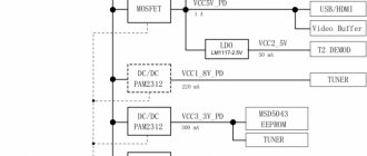
It was decided to replace the faulty switching stabilizer chip with a linear stabilizer with an output voltage of 1.3 V on the KR142EN12A chip, the circuit of which is shown in Fig. 1 (positional designations of its parts begin with the prefix 1). The output voltage is set by resistors 1R1, 1R2. The lower the resistance of the first of them (with the second remaining unchanged), the lower the output voltage. Capacitors 1C1, 1C2 are blocking. Diodes 1VD1 - 1VD3 protect the load from damage if 1DA1 malfunctions. Taking into account the voltage drop on the connecting wire, the output voltage of the stabilizer was approximately 1.28 V.
Rice. 1. Stabilizer circuit
The parts of the new voltage stabilizer are placed on a circuit board measuring 22x22 mm. The KR142EN12A microcircuit is installed on a ribbed duralumin heat sink, which is tightly pressed to the bottom and side walls of the metal case of the set-top box. Since the heat sink flange of the microcircuit is electrically connected to pin 2, it is fixed to the heat sink through an insulating gasket; a PVC tube and a getina washer are put on the mounting screw for insulation. All mating planes are lubricated with heat-conducting paste. Instead of KR142EN12A, you can install KR142EN12B or one of the imported ***317 series in the TO-220 housing (for example, LM317, KA317). The purpose of the pins of all these microcircuits is the same. A view of the installation of the stabilizer and the “stuffing” of the attachment is shown in Fig. 2.
Rice. 2. View of the installation of the stabilizer and the “stuffing” of the console
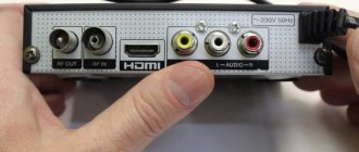
The stabilizer input is connected to fuse link F1 (Fig. 3, red wire), the output is connected to inductor L4 (Fig. 4, green wire), and the common wire is to the negative plate of capacitor C35 (Fig. 4). Instead of 1N4001 diodes, you can use any of KD208, KD243, KD247, 1 N4002-1 N4007.
Rice. 3. Circuit board
Rice. 4. Circuit board
The M3103-0C circuit board can be used in other models of DVB-T2 receivers. Since the author has never come across “cold” DVB-T2 set-top boxes (they all get very hot during operation), after the end of the warranty period, it is advisable to measure and record the input and output voltage values of the stabilizers installed on the board, and also photograph the circuit board on both sides like this so that all the inscriptions are visible, this can be useful when repairing a failed device. Keep in mind that several operating voltages can be generated simultaneously at the output of a pulsed integrated stabilizer. To improve cooling, you can install a small “laptop” fan inside the console.
After the repair, the current consumed by the tuner from the power supply was about 0.75 A, which means that the external complete switching power supply with the output parameters indicated at the beginning of the article is capable of providing power not only to the DVB-T2 set-top box, but also to the external one connected to it. hard drive form factor 2.5 inches. If the set-top box is equipped with a power supply built into its case, it is advisable to power 2.5″ hard drives from an external unit to reduce the load on it and, accordingly, to reduce the temperature inside the case.
Date of publication: 01/20/2016
Readers' opinions
- genn / 11/12/2017 - 07:30 Well told - thank you
- admin / 10.31.2017 — 10:17 Unfortunately, there is no scheme!
- ALEXANDER / 10.30.2017 - 19:00 Globo GL50 diagram where to find
- Victor / 03/19/2017 - 11:47 Thank you! Interesting. Educational.
- Vladimir Vasilyevich / 12/29/2016 - 13:59 I’m 69. I’m still interested. I liked the site and the sections. Since I’m still doing repairs on the r.p. since 1967.Thank you 73.
- Guest / 02/07/2016 — 20:23 The article will be useful to a certain circle of people, I liked it.
I have two TVs in my house and they both work through Cadena dvb-t2 set-top boxes, and it turned out that at about the same time they both stopped working. Repairing such a set-top box costs approximately from 600 to 800 rubles, a new one costs from 1200, which turns out to be both expensive. It was decided to try to fix it myself, to do this, by googling the Internet, a solution was found, which I want to show you. As it turned out, this is one of the main breakdowns.
The main symptoms of a broken set-top box:
- when you turn on the set-top box to the network, the red indicator lights up and the set-top box no longer responds to anything.
Set-top box repair process
First of all, we disassemble the console and carefully examine its insides, special attention should be paid to the capacitors. As shown in the photo (circled in red), the capacitor is swollen, unlike the capacitor (circled in blue), therefore it is no longer working and needs to be replaced.
Then we unsolder the capacitor, look at the parameters and look for a suitable one. In this case, 10 volts and 1000 microfarads, as well as 105 degrees Celsius, are required. But in my case, there was only 10v1000mf and 95Hz available, and it is a little smaller in size, but as practice has shown, it works great.
Now we solder the new air conditioner in place of the old one and, as you can see in the photo, everything is fine. (marked in blue).
The most common malfunction of digital television set-top boxes is the failure of the power supply. In such an unpleasant case, it is very good if the model of the console had an external adapter, buy a new one and look further! And if not! And was the power supply built into the console itself? Then you will have to repair or purchase a new one. But perhaps there is an easy way out!
Hello, dear readers! In this article I want to share one simple repair method that anyone who knows how to hold a screwdriver and a soldering iron can do! Moreover, it is not necessary to master these instruments masterfully.
I’m also not going to tell you anything overly complicated in the field of electronics repair; this is the domain of professionals. On the contrary, I will try to describe everything in such a way that even a non-specialist could cope and eliminate this malfunction.
I’ll immediately make a reservation that this method is not suitable for all models of consoles, but for many, since they are often made according to a very similar scheme for this case. Everything will be based on a specific example of a set-top box from the D-Color company, namely the DC1401HD model. So, having understood this “high technology”, you can repair your digital television set-top box yourself.
Quick navigation through the article
Connecting CPU to PPU
The next thing I did was the communication between the CPU and PPU. To do this, I used a “simple solution” which consisted in purchasing a dual-port RAM, this is a RAM chip that can be connected to two different buses at once. This allows you to get rid of additional chips like line selectors and, moreover, allows almost simultaneous access to memory from both chips. The PPU can also directly access the CPU on each frame by activating its non-maskable interrupts. It turns out that the CPU receives an interrupt on every frame, which is useful for various timing tasks and for understanding when it’s time to update the graphics.
Each frame of interaction between the CPU, PPU and VPU occurs according to the following scheme:
- The PPU copies information from the PPU memory to the internal memory.
- The PPU sends an interrupt signal to the CPU.
- Simultaneously:
- The CPU jumps to the interrupt function and begins updating the PPU memory with the new graphics state. The program must return from the interrupt before the next frame.
- The PPU renders the image based on information previously copied to one of the VRAMs.
- The VPU sends the picture from another VRAM to the TV output.
Around the same time I started supporting game controllers, at first I wanted to use controllers from Nintendo, but the sockets for them are proprietary and generally difficult to find, so I settled on 6-button controllers compatible with Mega Drive/Genesis, they have standard DB-9 sockets which are everywhere.
DIY console repair
What is a sign that the power supply in the set-top box has failed, and not something else? If the set-top box connected to the outlet does not show any signs of life, neither the digital indicator nor the LED on the front panel lights up, then with a 99% probability the reason is in it, in the power supply.
If at the same time the warranty period has already expired, then you can safely start disassembling it. As experienced craftsmen say, “An autopsy will show.” I think you can figure out this part of the work without a detailed description, just be careful, usually two screws on the back wall, sometimes also on the sides, allow you to release and open the top cover. Plastic latches on the sides and bottom hold the front panel, and the board itself is also secured with screws to the bottom of the case and in the area of the connectors on the rear wall of the case.
So, the set-top box is disassembled, the power cord is also removed from the connector, it will no longer be needed. On the bottom of the case there are traces of a “fire” left behind by a burnt-out power supply.
PS The power supply here is not a separate unit, as you might think from the name, but a section of the board on which radio elements are located that provide the required supply voltage to the set-top box.
What is the modification?
I’ll outline the general picture, and for those who already know a little about radio engineering, this will already be enough to grasp the basis of the idea and repeat it. So, the power circuits of this set-top box produce only one voltage - 5 Volts. Since this circuit has burned out and repairs may not be practical (given the total cost of radio components and repairs), there is a simple solution. Replace the internal power supply with an external one. It's not very difficult!
In the photo above, a yellow frame highlights the area of the power supply that has failed. The board has already been washed so no traces of burning are visible. By the way - Among repairmen, the expression “Burned out” does not always mean literal combustion with charring and other similar manifestations, it only means that the radio components have failed.
For our repair, you will need to purchase an external power supply with an output voltage of 5 Volts and capable of delivering a current of 1.5 or better 2 Amperes. Nowadays there are a lot of similar ones that can be purchased inexpensively, or maybe you have something similar, for example, an unused charger from a tablet or smartphone.
When a suitable adapter is available, all that remains is to find the desired point on the set-top box board and, observing the polarity, apply voltage to it from the external power supply. All! All that remains is to lay and secure the wire, or you can organize a detachable connection, as you like. I think the basics are clear, let's move on to the details.
Video signal
The first thing I did was generate a video signal.
Any console from the period I sampled had different proprietary graphics chips, meaning they all had different specifications. For this reason, I did not want to use an off-the-shelf graphics chip; I wanted my console to have unique graphics specifications. And since I could not make my own graphics chip, and at that time did not yet know how to use an FPGA, I decided to limit myself to software generation of the graphics signal using an 8-bit, 20 megahertz microcontroller.
This is not overkill, and just a powerful enough solution for graphics of the level that was interesting to me.
So, I started using the Atmega644 microcontroller at 20 MHz to generate a PAL video signal for the TV. I had to bit-ban the PAL protocol, since the chip itself does not support it.
The microcontroller produces 8-bit color (RGB332, 3 bits red, 3 bits green and 2 bits blue) and the passive DAC converts it all to RGB. Luckily in Portugal almost all TVs are equipped with a SCART connector and they support RGB input.
A short introduction to the power supply circuit of the set-top box
Just a little background for those who are not in the know so that you can figure it out. Pay attention to the photo. Click to enlarge.
In short, the power supply consists of:
- The primary “Hot” part - It is called Hot because it is dangerous, connected to the mains voltage of 220 volts. Please note that even after unplugging from the socket, there is still a charge there for some time that can cause damage..