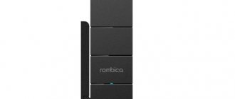
Set-top box (receiver) for TV
is an electronic device designed to convert a high-frequency signal coming from a television antenna into a low-frequency signal for a TV or monitor that is not capable of receiving a digital signal of the DVB-T2 standard directly.
The number of set-top boxes due to the transition to digital broadcasting in Russia has increased significantly, and like any electronic device, it can break down at any time. But, despite the variety of models, the operating principle and circuit design of all consoles are the same and they differ only in the presence of additional functions.
The set-top box is a minicomputer, and at first glance it seems beyond repair, but usually radio elements fail, which can be successfully replaced by a home technician.
CIRCUIT FAILURE
Here everything depends on the quality of the circuit elements, therefore well-known brands producing DVB T2 tuners that use a higher quality element base are more preferable.
The easiest way to diagnose a breakdown is when the indicator (light on the panel) does not light up. This clearly indicates a faulty power supply.
If the light is blinking, this may indicate a malfunction of the power supply unit or the chassis (this is the main board with the tuner and processor) of the set-top box, as well as a firmware failure.
In the case when the device spontaneously, repeatedly reboots and does not turn on, the same elements of the set-top box may be to blame. You can read about such repairs. If the display says “ON” and the indicator lights up green, but the set-top box does not turn on, then this may also indicate a circuit malfunction.
Repairing a DVB-T2 digital set-top box using a multimeter
If you have a multimeter, you can repair the set-top box faster and identify other faulty elements.
Checking the switching power supply
The top cover is removed and the set-top box is connected to the network. Next, the multimeter is switched to the mode of changing the constant voltage and its value is measured at the cathode of the Schottky rectifier diode relative to the common wire. It should be 5 V. The voltage can also be measured at the terminals of the capacitor, indicated by the number 1.
If the voltage is less than 4.8 V or absent, then the reason may be a malfunction of capacitors 1, 2, 6, the Schottky diode of the power supply or voltage converters.
To determine which half is faulty, you need to remove the cathode terminal of the Schottky diode (usually there is a marking in the form of a ring on the diode body near the cathode) from the board and test it with a multimeter.
If the diode is working properly, solder any electrolytic capacitor with a plus to its soldered terminal, and its second terminal to the common wire of the board. It is not recommended to turn on switching power supplies without a load, so you need to solder a resistor with a resistance of 50-100 Ohms in parallel with the capacitor.
Turn on the set-top box and measure the voltage on the capacitor. If it is equal to 5 V, then C1 or one of the voltage converters is faulty. C1 is soldered off and connected instead of the additional one. If voltage appears, one of the secondary converters is definitely faulty.
If voltage does not appear after the steps described above, then the power supply is faulty. In this case, you can still check capacitors 3, 2 and 6.
If the power supply cannot be repaired, then you can replace it with an external one, for example, an adapter for charging cell phones, which usually output 5 V. It is necessary, observing the polarity, to solder the positive wire of the adapter to the point of the soldered Schottky diode, and the negative wire to the common wire. I repaired my slow cooker in a similar way. The adapter must provide a current of at least 0.5 A.
FIRMWARE
As noted above, in some cases it is quite difficult to separate whether the firmware or the electronic part of the circuit is causing the malfunction without additional measurements. But if the tuner does not turn on after flashing the firmware, then the conclusion is clear: it is the one that is faulty.
Here you need to warn that you need to be careful when updating, follow the instructions and install exactly the firmware that is required for your device.
If such a malfunction occurs, you need to contact a service center, although not every center undertakes such repairs.
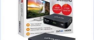
Oriel 314d is an ideal option for lovers of high-quality Dolby Digital sound
The index at the end of the model name means support for AC3 Dolby Digital sound, which makes this receiver model a priority for fans of good sound. Oriel 314d has a display indicator for switching TV channels; in standbay mode it shows the time. On the front panel of the set-top box there are three buttons, two for switching channels and one button for putting the receiver into standby mode. There is also a USB connector on the front panel, which can be used to replace software and play media files. Tests conducted by our specialists showed the omnivorous nature of the media player. On the rear panel there is an input and output for the antenna; the output will allow you to connect another set-top box to one indoor antenna. There are also RCA and HDMI outputs on the back for connecting the set-top box to a TV. The small body of the set-top box allows it to be placed even in narrow spaces. The power supply on the receiver is built-in and there are holes in the case for cooling it. It is not recommended to block the ventilation holes, as this can shorten the life of the tuner. The Oriel 314d package is quite simple and consists of a receiver, remote control, operating instructions and batteries. The connecting cable to the TV is not included in the package, you will have to buy it separately. So the price for an RCA cable (tulips) will be 150 rubles. and the same price for a 0.7m long HDMI cable. You can buy Oriel 314d in our store in Moscow or order delivery throughout Russia. Each dvb t2 receiver comes with the latest firmware and is checked in front of you when you come to our office.
REMOTE CONTROLLER
Many cheap models of set-top boxes do not have control buttons on the front panel, and this is a significant disadvantage since if the remote control malfunctions, you will be unable to control the tuner at all. This has already been written about on the website in an article about choosing a console.
Therefore, if the remote control for a digital set-top box does not work, only purchasing a new one or a repairman will help identify it. Unfortunately, remote controls for tuners are still rare and quite expensive.
It happens that the tuner does not turn on from a long distance; here, both the tuner and the remote control itself may be to blame (which is rare). You can try replacing the batteries, but if that doesn’t help, buy a new one. If in this case there is a negative result, then the prefix is to blame.
Once again, without special skills, it is difficult to solder the parts yourself, which can cause great harm to the board.
The fleet of analogue TVs is rather reluctant to give way to digital equipment, gradually taking “second” places - in the kitchen, in offices, garage workshops, etc. At the same time, DVB-T2 set-top boxes are also carried. We have already managed to evaluate the advantages of the latter; some owners also appreciated the disadvantages - the rather low reliability of these devices. As a rule, one of the weakest points of this kind of equipment is the switching power supply - most cases of failure are associated precisely with a malfunction of the power supply, and a malfunction of the power supply can entail such serious consequences that repairing the device will be impossible. And yet, using the example of two digital TV set-top boxes, the possibility of repairing them independently will be considered here. The first device was TVK 3101. When turned on, the image had severe distortion and periodically disappeared completely. A few days later, the set-top box began to turn off a few seconds after the manufacturer's logo appeared on the screen.
The second device is the Oriel 740 set-top box. This device did not respond to commands from the remote control, the indicator barely glowed red.
After opening the console cases, it turned out that in both cases the electrolytic capacitors of the secondary power filters were swollen.
It should be borne in mind that when working with the set-top box, special care should be taken - the primary power supply rectifier converts an alternating voltage of 220 volts into a constant voltage of about 300 volts, and this potential remains at the terminals of high-voltage electrolytic capacitors for some time after the power is removed - up to several tens of seconds . In the pictures they are located between the pulse transformers and the plugs of the power cords. Before working with the device board, these capacitors must be short-circuited through a resistor with a resistance of 51-62 kOhm.
Both faulty capacitors turned out to be almost the same - 1000 µF, 10 V. The picture shows one of them. The fact that its lid looks barely deformed should not give you the slightest confidence in the serviceability of the part - even if some part of the container has been preserved, such a part will have an increased leakage current, which is unacceptable. When replacing, you should select capacitors with the same operating voltage or with a slightly higher one, as in the picture - instead of a 10-volt part, a 16-volt part is shown, and with the same dimensions. Of course, faulty parts should be replaced with new ones, not used ones - otherwise the repair will soon have to be repeated.
After replacement, we turn on the set-top box - the indicator lights up brightly, the device responds to remote control commands, the image is stable. But the renovation is not finished yet...
There are traces of flux on the board - solder paste, rosin... Through such a coating, high-frequency currents can quite easily pass wherever they want. As a result, over time we may get an unstable image, noise, etc. troubles. Therefore, carefully wash the board with a cotton swab moistened with alcohol or acetone. After such cleaning, wipe the board with a dry cotton swab.
We install the board in place, check - it works.
Now we assemble the console completely and check its functionality again.
We check the second device in the same way - the device is working normally, the repair is completed.
In conclusion, I will add that the quality of the antenna amplifier power supply also greatly affects the operation of the set-top box. Thus, if the capacity of the filter capacitor is insufficient, signal loss is possible - there have been cases of complete loss of channels of the second multiplex. To recognize a malfunction of the antenna power supply, it is enough to replace it with a DC source of 9-12 volts (for example, a Krona battery or a battery from a computer uninterruptible power supply). If the reception quality improves, you should replace the antenna power supply with a known good one.
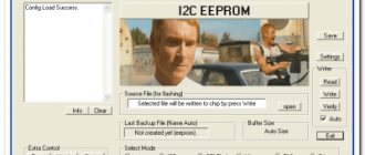
Updating the software (firmware) of your equipment is carried out only in cases where any problems arise, or the update will add useful functions to the device. Flashing devices unnecessarily is not recommended, because... During the firmware update process, there is a possibility of equipment failure. If you are not sure that you can handle updating the firmware on your own, we recommend contacting the appropriate service center and qualified specialists.
Download ORIEL firmware file:
Oriel 810 receiver firmware file - (version 3.4) This update is only suitable for receivers with serial numbers from 81111200001 to 81111205050 and from 81120100001 to 81120106060. . Oriel 820 receiver firmware file - (version 1.0 dated 08/01/2012). This update is only suitable for receivers with serial numbers from 82120100001 to 82120105280. . Oriel 710 receiver firmware file - (version 1.3.5). This update is only suitable for receivers with serial numbers from 710121000001 to 710130211200. Oriel 720 receiver firmware file - (version 1.3.5). This update is only suitable for receivers with serial numbers from 720121000001 to 720130202200. The Oriel 910 receiver firmware file is . Oriel 920 receiver firmware file - .
Official website of the manufacturer:
You can check the availability of newer software on the official website of the manufacturer - You can ask questions about ORIEL brand swing equipment through.
How to update firmware:
Proceed as described in the user manual. If this information is not in the manual, contact technical support for your equipment.
Useful links:
In order to unzip the firmware file, you may need an archiver program. One of the most popular is .
Do-it-yourself TV set-top repair
They contacted me with a request to repair an Oriel 750 model set-top box to receive a digital signal on an old TV. According to the owner, the set-top box first periodically stopped receiving a signal, and over time it stopped working altogether. At the same time, the console worked for several years before breaking down.
The peculiarity of the operation of a TV with a set-top box is that the TV is controlled by its own remote control, and the set-top box is controlled by its own. Using the TV remote control you can turn on the TV, select the signal source and adjust the volume. Setting up TV channels and switching them is carried out from the console remote control.
Therefore, if the TV turns on from the remote control, but the set-top box does not turn on from its remote control, then first of all you need to check whether the power cord plug is inserted into the socket and whether there is voltage in the socket.
Next, you need to check the suitability of the batteries in the remote control. If you have a multimeter, you can measure the voltage on each battery, which should be at least 1.5 V. If the device is not available, replace them with a known good one.
If the TV remote control works and its batteries are the same size as those in the set-top box remote control, then you can swap them to check. Perhaps there are other electrical appliances in the apartment that have suitable batteries or accumulators installed.
Checking the batteries of the remote control and its performance using an oscilloscope showed that the remote control is working. I had to open the console. To open it, you only needed to unscrew a few screws.
As the practice of repairing electronic products shows, in 70% of cases electrolytic capacitors in power supplies fail. The console was no exception. Upon inspection, a swollen electrolytic capacitor installed at the output of the set-top box's power supply was immediately discovered.
As can be seen in the photograph, the end of the cylindrical body took the shape of a sphere instead of a plane. The capacitor can also swell due to a faulty power supply, but this happens very rarely. Therefore, to repair the set-top box, you must first replace it with a working one.
Before repairs, you must disconnect the set-top box from the power supply. To resolder the capacitor, you need to remove the printed circuit board from the case, to do this, unscrew three screws and move them away from the external connectors so that they come out of its case. To make repairs easier, you need to disconnect the power cord from the board. It is connected to it using a connector.
When installing electrolytic capacitors, polarity must be observed. They usually have a light stripe along the body on the negative terminal (minus) side, and the board is marked in the form of a shaded area next to the negative terminal seal hole, as shown in the photographs.
If a capacitor with the same parameters is not available for replacement, then you can take one with a larger or slightly smaller capacity. The main thing here is that the operating voltage of the capacitor is no less than that indicated on the swollen capacitor. It is always better if the capacitance and voltage of the electrolytic capacitor is greater than that of the failed one.
If a capacitor suitable for the parameters has large dimensions, then it can not be installed in its standard place, but can be glued with silicone or Moment glue to the board next to it, and its terminals connected to the printed circuit board using pieces of wire.
The new capacitor is soldered into the board, and you can check the operation of the set-top box. To do this, it is not necessary to install the board into the case. You can place it on the table and, to prevent a short circuit between solders, place a sheet of dielectric material under the board.
If the set-top box has a digital display, then you can check it without connecting to a TV. If it turns on from the remote control and the channels are switched, then the problem has been resolved. If there is no display, you can rely on the power indicator, which should change the color of the light when you turn the console on and off.
Connecting the set-top box to the TV proved its functionality. All 20 digital channels were broadcast steadily. If you accidentally forgot how the set-top box was connected to the TV, then I’ll provide a connection diagram to help. The TV is connected to the set-top box using one of two cables: HDMI or RCA. If your TV has an HDMI connector, it is better to use it. The quality of TV programs will be higher.
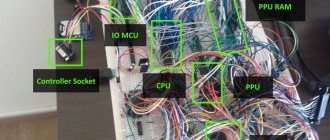
All set-top boxes for receiving a DVB-T2 television signal from an antenna have almost the same electrical circuit, with minor differences in the installation of the printed circuit board. Therefore, the described instructions are applicable when repairing a digital set-top box of any model.
Repair of digital set-top box DVB-T2 without devices
If, during an external inspection of the set-top box board, burnt radio components are not found, then you will have to start looking for the failed part. A home handyman may have access to one of two repair methods, without instruments and using a multimeter. But in any case, you need to imagine what components the electrical circuit of the set-top box consists of.
The 220 V AC supply voltage from the network is supplied using a power cord to the input of a switching power supply, which converts it to +5 V DC voltage.
To power the processor, memory, demodulator, tuner and other components, secondary power supplies are used, which convert the +5 V voltage to a lower voltage: +3.3 V, +1.8 V and +1.2 V. To smooth out ripples in Each of these blocks has electrolytic capacitors installed. This is where they most often fail. The capacitor plates may short-circuit with each other or become detached from the terminals.
Therefore, repairing a set-top box without instruments consists of sequentially replacing all electrolytic capacitors with known good ones.
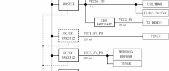
In the diagram above, the order of replacement of electrolytic capacitors is indicated by blue numbers based on the likelihood of their failure.
As you obviously guessed, the repair consists of sequentially replacing all electrolytic capacitors installed on the board. After replacing the next capacitor, you need to apply supply voltage to the console and check its operation.
If the set-top box cannot be repaired by replacing the capacitors, it means that the active elements are faulty, and it is almost impossible to find them without instruments. You'll have to contact service or buy a new one.
Oriel 304 receiver repair
And so in the end it turned out that two capacitors, 10 microfarads 25 volts and 1000 microfarads 10 volts, were faulty; they were all replaced with 10 microfarads 63 volts and 1000 microfarads 25 volts, after which the receiver turned on.
Now we assemble and test.
Tools and consumables used in this repair.