Hello, dear readers of the site. From April 15, 2021, broadcasting of analogue programs will be canceled in most regions of the Russian Federation due to the transition of terrestrial television to digital format
.
Digital television broadcasting Digital Video Broadcasting - DVB is divided into:
DVB-T (Terrestrial) - terrestrial - modifications T, T2; DVB-C (Cable) - cable; DVB-S (Satellite) - satellite - modifications S, S2
In Russia, the DVB-T2 format is used, to receive which the TV or receiver must have a DVB-T2 tuner. Tuners with the letters T, C and S are not suitable for work in Russia.
First of all, the refusal to broadcast in analog format will be felt by users of individual antennas and residents of houses not connected to cable networks. In large cities, the television signal is transmitted from cable operators, who must leave analog programming unchanged.
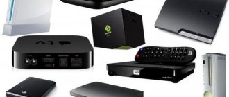
This certainly raises a question. What should you do if you are completely satisfied with the TV you bought several years ago, but it does not support the DVB-T2 format? Everything is simple here. It is not necessary to change the TV itself and spend a lot of money on purchasing a new one. It is enough to buy an external DVB-T2 receiver and connect it to the TV with an HDMI cable or other available method.
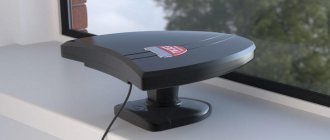
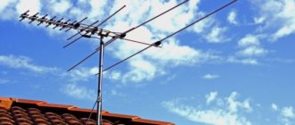
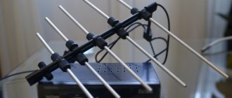
The terrestrial digital signal is received by a conventional TV antenna that receives UHF frequencies. If you did not have an antenna at all or you want to refuse collective television services, purchase any UHF antenna.
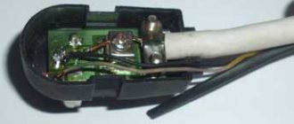
From personal experience it has been established that there is no particular difference between an active and passive antenna. You can even make it yourself, for example, from a piece of coaxial cable, as shown in the picture below. The antenna loop diameter is only ~15 cm.
Of course, this is a surrogate, but on the receiver scale the level/
There is no significant deterioration in quality compared to purchased antennas.
Here is another version of the simplest antenna: the length of the working section is ¼ of the signal wavelength = 300/FmHz/4, where FmHz is the average frequency of the TV channel. For channel 30 (546 MHz) the length is 0.137 m or 13.7 cm.
Content
Many users are faced with the question of how to configure the receiver. Digital is becoming more and more popular, analog technologies are becoming a thing of the past. Internet and television in a private home, the specificity of which is that video broadcasting is carried out in Full HD quality. For digital TV you need a modern television receiver with a built-in Smart TV function; connecting will be quite simple, following simple instructions. And users of old television receivers should think about buying a set-top box. You can configure it yourself, or seek help from the experts. Manufacturers produce universal receivers that are suitable for receiving signals in any format. Modern set-top boxes have quite a lot of different connectors, which we will discuss below. Setting up a digital TV receiver is quick and does not require special knowledge and skills. Today we will look in detail at how to set up digital TV at home and in what ways you can quickly connect the set-top box to the TV receiver.
How to reset settings
If there is a malfunction in the robot, you need to reset everything to factory settings. Before resetting the receiver, experts advise carefully reading the step-by-step guide. This will help not only save time, but also nerves.
To do this you need:
- Enter the menu.
- Then settings.
- Enter the PIN code specified in the tuner instructions.
- Cancel factory settings and press the red button to confirm the action.
A warning will appear on the monitor indicating that previously saved data will be reset. You need to reconfirm the action.
After rebooting the tuner, you will be asked to select a language. Next, you should repeat the settings.
What equipment is needed for digital
Purchasing and setting up a receiver is the first step to creating digital TV in an apartment or house. The technology for transmitting a digital television signal is based on its encoding and distribution. This means that connecting the receiver to a television set is necessary in order to receive signals and decode them. Various devices can act as a receiver, it all depends on the TV broadcast format:
- Cable TV. The image arrives at the television receiver in a compressed format. You will need a high-quality cable with high bandwidth. It will carry out data transfer. The service provider maintains the receiving equipment.
- Satellite television. This format is currently also broadcast on digital TV channels. Satellite dishes are used as receivers. Users often ask the question: there are TVs with a satellite tuner, how to use them? You can install such equipment yourself or with the help of specialists. Using such equipment is easy if you carefully study the step-by-step instructions. Setting up a digital satellite receiver is quick. But, if you can’t figure it out on your own, it’s better to use the services of a specialist. Russian companies offer to connect television via satellite, the most popular of which are: Tricolor TV, Telekarta, NTV Plus, MTS.
- Essential. It works on the same principle as analog. A special decimeter antenna is required for use.
Each option has its own characteristics and advantages. For example, an obvious advantage of satellite technologies is territorial accessibility. This means that the user can connect such a TV in any area. The main condition is the availability of special equipment and its proper configuration.
1Why did the signal disappear?
If you have already set up a receiver, but suddenly the broadcast disappears and the message “No signal” appears on the TV screen, do not rush to set it up. The problem may not be in the receiver settings. There are several reasons why the signal may be lost:
- the cable connecting the antenna to the tuner was broken;
- technical work is being carried out (you need to call the support service and inquire about the operator’s work);
- The satellite dish settings were lost.
If you are sure that the problem is in the receiver, first of all you need to restart the tuner, just do not turn it off using the power button on the control panel, but unplug the power supply from the outlet and turn it on again after 1 minute. If the signal does not appear, then you need to go to the “Tuner settings” item.
Equipment
To organize one or another format of television broadcasting, you will need set-top boxes. In terms of cost, satellite equipment is considered the most expensive option. It will require an attachment, a receiving head and several reflectors. The receiver has several purposes:
- Decoder. Deciphers signals and transmits a picture.
- Dashboard. Using the set-top box, the user activates digital television, controls channels, and also receives signals using the remote control.
- Content support. The receiver is also used to quickly set up TV and unblock pay TV channels.
Connectors
Before setting up the receiver, you need to understand its connectors. Depending on the model of the set-top box and its purpose, devices are divided into profile and universal. You can buy such devices in a specialized online store or through a provider. You can also find universal models on sale that are equipped with many different connectors. The principle of connecting the receiver depends on the type of connectors and the TV broadcasting standard:
- RCA. This is the main connector through which the set-top box is connected to the television receiver. RCA is represented by 3 sockets, which are called “tulips”. Yellow is for video, and white and red are for audio. The wire plugs are also color-coded to prevent users from getting confused when making connections. The disadvantage of this technology is its rather weak throughput. This means that 1080p resolution will not be achieved in this case. Users should pay attention to one important nuance: the RCA cable is a power cable, so before connecting it, you need to turn off both the receiver and the TV.
- Scart. Simplified version of the previous connector. Compact set-top boxes are equipped with Scart connectors. To connect, you need to use the same wire with a Scart to RCA adapter.
- HDMI. Required for coaxial cable. All modern models are equipped with this connector. The HDMI connector provides Full HD image transmission, so if your receiver has several different connectors, it is best to use this one. Please note: in this case there is no support for analogue TV broadcasting.
- DVI and D-SUB. Such connectors require a special cable, which can be a wire that connects the monitor and the computer system unit.
- LAN Only Smart set-top boxes and universal models are equipped with such connectors. This input requires a special Ethernet cable. Technology makes it possible to watch interactive television.
- CAM module. They are equipped with satellite set-top boxes. Such modules are necessary for using cards to unblock pay TV channels.
- Antenna input - RF IN connector. Applicable to all models of TVs and set-top boxes.
Setting up a satellite receiver (preliminary setup of the receiver)
Unfortunately, I do not have the opportunity to describe the setup of each satellite receiver individually. In any case, given their large number, this is simply not realistic. Therefore, you will have to tell, relying only on some examples. The information presented below may differ from your version of the receiver model, but in its general principle the whole process is very similar. So, after reading this description, I think you will be able to figure out your receiver model. The only thing I can advise here is, don’t be afraid to change any parameters. If you forgot which option you changed, or are completely confused about the settings, then, as a rule, you can restore everything to its original state by selecting the “default settings” option in the menu, and then repeat everything step by step from the beginning.
First of all, when you turn on the satellite receiver for the first time, you should set up the language interface; usually the default is English, although... there may be another one. Navigate through the menu using the navigation buttons (arrows), and open submenus by pressing the “OK” key. Find and select the “language” parameter, then confirm our choice on the “Russian” inscription.
To make it easier to configure the satellite receiver, let's clearly define which parameters you need to enter into its memory. Let's divide the input of these parameters into two stages:
First stage: Entering into the satellite receiver the parameters of the gimbal type and the parameters installed on the satellite dish
converter. Second stage: Entering transponders (that is, transponder parameters) into the satellite receiver for the satellite to which the satellite dish is supposed to be tuned.
Since I will explain the receiver settings using a specific example, which I already described on previous pages, let’s remember what the parameters of the satellite dish
and its converter, as well as transponder data from the satellite from which the signal will be received.
I did not indicate the type of antenna and its diameter, since these parameters are not involved in setting up the satellite receiver.
I also did not indicate the noise figure and sensitivity of the converter, since they relate only to qualitative indicators and are also not involved in setting up the satellite receiver.
Satellite Express AM 22 53.0°E (53 degrees east longitude). To set up a satellite dish
, we will only need one active transponder, selected satellite.
Here it is advisable to select the transponder on which several TV channels (package) are broadcast at once. As practice has shown, such transponders change their parameters extremely rarely, and you will have a better chance that the satellite transponder you entered will be valid.
But all the same, whether it is a transponder with one channel or several, it always doesn’t hurt to check again (for example, on the Internet) whether any of its parameters have changed. If you enter outdated data, no information about setting up the satellite receiver, and even more so, no information about setting up the satellite dish.
, there is no question.
I'll get ahead a little. Setting up a satellite dish can be greatly simplified
, if, for example, one of your friends already has
a satellite dish
, which is tuned to the satellite you need. Connect your already configured receiver to it and scan the transponders of this satellite. This option will eliminate doubts on various occasions. For example, have you entered valid transponders, are your satellite receiver and converter working properly, etc.
Next, I will provide screenshots (photos from the screen) of the two aforementioned FTA receivers No. 1 and No. 2, and at the same time, explain some points. You should try to apply this explanation to your case.
First stage
Configuring the satellite receiver for the satellite dish configuration
On the remote control, press the MENU button and go to the main receiver settings menu. First we need to find a section such as “Antenna Installation” (or “Antenna Management”, “Antenna Setup”...).
In satellite receiver No. 1, this menu was located: Main menu User Settings Antenna installation (Photo 1).
In the receiver DRE - 4000, DRS - 5001 (receiver for viewing "Tricolor TV"): Main menu Settings System settings Antenna settings.
Find this section and click the “OK” button. Photo 1 The initial menu of this satellite receiver.
the satellite dish configuration opens before us
. Let's use receiver No. 1 (Photo 2) as an example to figure out what parameters are indicated there and which of them we need to change (or leave as is if they are already set correctly). In some satellite receivers, by default, the settings are locked with a password (which can be changed later), and as a rule, it is a set of four or five zeros, for example, you need to fill in four stars with these zeros - “****” “0000”.
Before continuing the explanation, so that you do not rack your brain unnecessarily, I would like to draw your attention to a certain point. It is connected with the translation of the language interface of the satellite receiver into our great and mighty Russian language. Some words may not exactly correspond to the functions that they directly mean. This most likely refers to flaws in computer translation. The fact is that after such a translation, the text must be checked and corrected, but apparently the producers neglect this, after which the result is such “abracadabra”. As an example, you can take the word “Recorded,” which denotes the type of antenna mounting. Who recorded it and where, probably only the producers themselves know. A more correct designation for this parameter is “Fixed” (rigid fixed suspension). So, turn on your imagination, and treat this with a bit of humor.
Now let’s look at each parameter of the “Antenna Installation” menu of this satellite receiver (Photo 2), separately:
Photo 2 Satellite dish setup
.
Antenna: can take values - “1,2,3...14,15,16”
- Serial number of the satellite dish
or converter. Modern receivers can support signal reception from several antennas or converters, which in turn allows you to alternately receive this signal from several satellites. You can see a diagram of five types of such connections here. Switching of antennas or converters is carried out using special DiSEqC switches (working according to the DiSEqC 1.0, DiSEqC 1.1... protocol).
satellite antenna suspension type
) can take values - “Recorded, DiSEqC 1.2, USALS”
- Written down (you may have a different word) - rigid fixed suspension (using this example, I will explain further settings
). - DiSEqC 1.2 - (with built-in positioner), controlled via DiSEqC 1.2 protocol. This parameter will be discussed in the "" section.
- USALS - . This parameter will be discussed in the "" section.
Satellite: can take values - (alas... the entire list of satellites will not fit here)
- Here I think it’s clear, the satellite to which the satellite dish will be tuned
. If more than one converter is installed on one antenna (the so-called “multifed”), the satellite to which this particular converter is tuned is indicated here.
Type of low noise block: (i.e. converter) can take values - “Universal, Normal, LNBF”
- At this point, you select the type of LNB, that is, the converter that is located on the satellite dish
.
LNB 1 frequency: can take values - “numeric parameter”
- Low frequency local oscillator of the satellite converter (low range).
LNB Fred. 2: can take values - “numeric parameter”
- High frequency local oscillator of the satellite converter (upper range).
0/12 Volt: can take values - “0 volt, 12 volt”
- If you turn on “12 Volts” in this menu, on the connector that is output to the rear panel of the satellite receiver, a “+12 Volts” DC voltage appears relative to the body of the receiver itself. That is, when you select any TV channel from this satellite, “12 Volts” will be supplied to the connector. Serves to control any external device.
22 KHz tone: can take values - “0 KHz, 22 KHz”
- Serves to manually switch the upper and lower ranges of some satellite converters (for example, linear universal), with a tone signal with a frequency of 22 kilohertz, or 0 kilohertz. “0 KHz” is the lower range, “22 KHz” is the upper range.
DiSEqC: can take values - “Port-A, Port-B, Port-C, Port-D”
- This indicates which input of the DiSEqC switch (if any) contains the antenna or converter that is tuned to the above-mentioned satellite. Depending on the receiver model, the values can be “Port A,B”, “Port A,B,C,D”.
“C” or “Ku”: can take values - “0/22 KHz, 0/12 volts”
- This parameter means which signal, the satellite receiver, will control the switching of the converter bands, which supports both C and Ku range, tone - 0/22 KHz, or constant voltage - 0/12 volts.
Unfortunately, in your case, the menu words may differ significantly from those stated above. Here the only way I will try to help you is to dwell on some parameters in more detail and explain where they come from.
Setting up the receiver for the converter (setting up the receiver for the converter installed on the satellite dish)
A signal from a satellite, with a certain polarization, falls on the satellite
, and is further reflected on the converter irradiator. The satellite signal of horizontal polarization - Horisontal (H), travels in the horizontal plane (Fig. 1).
Rice. 1 Horizontal polarization signal - Horisontal (H).
Vertical - Vertical (V), in the vertical plane (Fig. 2).
Rice. 2 Vertical polarization signal - Vertical (V).
In circular polarization, the signal seems to rotate in one direction or the other, conventionally called right - Right (R), and left - Left (L) polarization. Now let's figure out the frequency of the signal. As we already know, converters produced by the satellite industry have their own frequency range. As a rule, C or Ku are available to us.
These converters are also single- or dual-band. This explains to us why for some satellite converters you need to enter one frequency parameter (frequency - LNB 1), for others two (frequency - LNB 1 and LNB 2).
Why such complexity? The point here is that the satellite converter itself can only cover a certain part of its satellite signal range. Therefore, in order to expand its received frequency spectrum, another sub-band is added to it (LNB 1 + LNB 2), thereby increasing the capture of most of this satellite frequency spectrum.
Let's look at a specific example, the previously mentioned two satellite converters from Golden Interstar, “Ku” band. A universal linear converter with two outputs, supporting vertical and horizontal polarization, as well as a circular converter, right and left polarization, with one output.
Here are the frequency parameters of these two satellite converters:
Let's compare the frequency range of the converters with the frequency spectrum of the Ku band satellite.
Here you can clearly see that both of these converters capture only part of the “Ku” range, in the case of a universal converter with linear V and H polarization from 10.7 to 12.7 GHz, and with a converter with circular, right and left polarization, “11.7 GHz...12.5 GHz” (here for a linear converter the frequency spectrum starts at “10.7 GHz”, and for a circular converter at “11.7 GHz”).
A universal linear converter captures, although not all, most of the Ku range (since it is two-band), and a circular polarization converter is only a third of it. This is due to the technical capabilities of the so-called “heterodyne”, which is located inside the satellite converter itself.
A local oscillator is an electrical oscillation generator used to convert frequencies in radio electronics. In this case, it serves to convert the frequencies of the satellite signal coming from the satellite.
A heterodyne has its own specific frequency. In the first case, a universal linear converter, in order to expand the frequency spectrum of the received signal, has two such local oscillators, which divide the entire received range, as it were, into two subranges, lower and upper.
To control switching between the converter's local oscillator bands, the satellite receiver produces a tone signal with a frequency of 0 KHz or 22 KHz. If the receiver sends a 22 KHz tone signal to the converter, the upper range is turned on (11.7 GHz...12.7 GHz), if 0 KHz (i.e. there will be no control signal to the converter at all), then the lower one (10. 7 GHz...11.7 GHz). In some converters, ranges can be switched with a constant voltage of “0/12 volts”; if there is no voltage, then the lower range is switched on, and if “+12 volts”, then the upper range.
The circularly polarized converter described above has only one local oscillator (this explains its smaller coverage of the “Ku” range), so there is no need to switch between its subbands.
Where do you get these parameters? As I already said, the technical parameters of a satellite converter can be taken from the tag on the body of the converter itself, or from the packaging box, or from its technical data sheet.
Again, for clarity, we will analyze both of the above-mentioned converters, separately, using the example of setting up satellite receiver No. 1, in the satellite dish setup
.
In order to be less confused about the names in the paragraph “Type of low noise unit” (converter), I recommend looking not only at the name itself, but also at the local oscillator frequencies of the converter subbands.
In the example I offer, they are called “LNB Frequency 1” and “LNB Freq. 2". Which corresponds to the frequency of the lower local oscillator (9750 MHz) and the upper one (10600 MHz), see Photo 3.
Photo 3 Entering parameters of the universal converter.
If you have not found the name you need, you can enter the converter frequency parameters manually using the number buttons on the remote control, which in satellite receiver No. 1 corresponds to selecting the name “Normal” (Photo 4). That is, when choosing this name, it becomes available to us to edit the frequencies of the local oscillator (LOs) of the converter itself.
Photo 4 Entering universal converter parameters manually.
In the previous photo (Photo 3), the input of the local oscillator frequency parameters is blocked, darkened with a pale or background color, thereby offering to sort through the type names, making it easier for beginners to choose the type of converter.
Important! Before changing any parameters, I want to warn some owners of satellite receivers. There are receivers that initially block manual input of these parameters. For example, it is impossible to manually enter the values of frequencies, type of polarization, etc. This is done so that a novice user does not unknowingly enter any chaotic data. How to unblock the entry of this data? As usual, such receivers have options like “Beginner” and “Expert”. The default mode is usually “Beginner”. Find these options, and be sure to switch to advanced user mode. And only after this, you will be able to edit previously inaccessible values and options.
And so, let's return to entering the converter parameters. Since not all the necessary parameters were listed on the label of this converter, I took them from the packaging box (Photo 5):
Photo 5 The parameters of the satellite converter are indicated on its packaging.
We enter the parameters of this converter (linear universal) into the satellite receiver:
Type of low noise unit (converter):
- If I had chosen the “Universal” option, the local oscillator frequencies would have been set by default (only for this type of converter). If you select “LNBF”, this will mean that
we have a “C-band” converter the satellite dish Here I will select the “Normal” value, since, for this model of satellite receiver, this will allow you to enter the local oscillator frequencies manually.
LNB frequency 1: Here you need to enter the frequency value of the lower local oscillator.
- We look at the parameters indicated on the converter packaging.
- And we enter the number “9750”, that is, the frequency of this local oscillator in megahertz (MHz).
LNB Fred. 2: Here you need to enter the frequency value of the upper local oscillator.
- Let's look again at the parameters indicated on the converter packaging.
- And enter the number “10600”, again in megahertz (MHz).
The remaining parameters indicate various types of switching, I will leave them at default. I will dwell, perhaps, on the parameter that directly concerns the operation of the satellite converter itself.
On the packaging of this converter there were also the following parameters:
They explain which signal the receiver will use to switch the converter between local oscillators. This immediately begs the question: where should these parameters be written? The answer, if in manual mode, following the example of receiver No. 1, fits into the manual selection (Photo 4, eighth line) - “0 KHz” is the lower local oscillator, and “22 KHz” is the upper one. And if you set the value to “No”, then this receiver will automatically, after you register the transponder frequency (in the setup
transponders), will produce the required signal to control
the converter
, corresponding to exactly this range.
To complete the information, let’s look at one more parameter. On the packaging box of the converter, the frequency ranges of coverage for both local oscillators were also written:
Frequency range of coverage, lower local oscillator of the satellite converter.
And the frequency range of coverage, the upper local oscillator of the satellite converter.
Based on this, based on the transponder frequency, you can determine which local oscillator your converter will operate on. Let's take any individual transponder from the Express AM 22 satellite:
Judging by the parameter 11044 MHz, we can now say that when viewing channels from this transponder, the lower local oscillator (Low band) will work, since this frequency is in the range of 11700...12750 MHz. This means that the receiver will send a “0 KHz” tone signal to control the converter (that is, since the value is zero, there will be no signal at all).
As you can see, there is nothing too complicated here. Whatever the frequency parameter of the one installed on your satellite dish
, converter, this parameter can always be entered manually.
We've dealt with the two-band converter, now let's look at the single-band converter.
Next, we will look at setting up the receiver, using the example of installation on a satellite dish
a circular converter that has only one local oscillator, that is, a single-band converter (Photo 6).
Photo 6 The parameters of the satellite converter are indicated on its packaging.
In principle, everything is the same here, only even simpler. Since, in the converter example I give, there are not two local oscillators, as in the previous one, but one. This means that you only need to indicate one frequency (Photo 7).
Photo 7 Recording parameters of a single-band converter, which has one local oscillator.
We enter the parameters of this circular converter into the satellite receiver:
Type of low noise unit (converter):
- In this model of satellite receiver, in the satellite dish setup
, there is no pre-made item for this type of converter. Therefore, here I will select the “Normal” value, since this will allow me to enter the local oscillator frequencies manually.
LNB frequency 1: Here you need to enter the frequency value of one single local oscillator of this converter.
- We look at the parameters indicated on the converter packaging.
- And we enter the number “10750”, that is, the frequency of this local oscillator in megahertz (MHz).
LNB Fred. 2: Here you need to enter the frequency value of the upper local oscillator of the converter.
- In place of the frequency, the upper local oscillator, you can specify any numerical parameter, in this case, it does not matter, for clarity, that this converter has one local oscillator, I entered five zeros, “00000” (Photo 8).
In a single-band converter, there is no need to switch local oscillators using the “0 KHz” and “22 KHz” tone signals, because why switch them if there is only one local oscillator.
To conclude the discussion of the receiver menu item “Antenna Installation”, I will give an example of setting up a satellite dish
in receiver No. 2 (Photo 8).
Photo 8 Satellite dish setup
and transponder selection.
Satellite dish setup menu
, satellite receiver No. 2, are somewhat different from the previous one... In this receiver, the manufacturers decided to slightly combine the menu
for setting up a satellite dish
and selecting a transponder.
I won’t consider similar parameters; I think it’s already clear here. I will skip the last three points for now, since they relate to the parameters of transponders, and we will look at them later. I will only dwell on the important differences for the “Antenna Installation” menu of this receiver from the previous one.
Pay special attention to the fifth menu item. This specifies whether power will be supplied to your converter. Why turn off the power to the converter? You ask . After all, if the voltage is not turned on, then there can be no talk of any reception of a satellite signal.
Yes, you really won’t be able to receive anything, but imagine this option... You have one satellite dish with a converter that has one output, and two receivers, each of which is in different rooms. How to connect two receivers to one satellite dish?
Connecting two receivers
As I already mentioned on previous pages, almost any satellite receiver has a so-called pass-through output (Photo 9 and Photo 10), and through it the second receiver is connected.
Photo 9 Satellite dish input and receiver pass-through output No. 1.
Please also note that for these two receivers, the location of these two connectors will be mirror opposite.
Photo 10 Satellite
and receiver pass-through output No. 2.
Now, we need to connect two receivers in series. Let's assume receiver No. 1 is directly connected to a satellite dish
. And receiver No. 2, through the pass-through input of the first (Fig. 3).
Rice. 3 Diagram for connecting a satellite dish
to two receivers.
The first receiver here will be the leading one, that is, as if the main one, it will supply power and control the converter. The second, slave, will only receive the signal. Therefore, in this case, the “Power” option in receiver No. 2 must be switched to the “OFF” position, that is, it is necessary to prohibit the supply of voltage to the coaxial cable intended for the operation of the converter (since it is powered from the first receiver). If this is not done, then let's imagine what will happen...
Let's assume that the satellite dish setting
, has already been carried out to some satellite. On the first, leading receiver (main), we watch the channel, which is in vertical polarization, which corresponds to the power supply to the “14 volt” converter. Here, everything will be fine until you switch on the second slave receiver to a channel that will be in horizontal polarization. In this case, the second receiver will supply power to an “18 volt” converter, which in turn, with a high voltage, will switch this converter to horizontal polarization, which will naturally affect the viewing of TV channels on the first receiver.
In practice, there were cases when this happened. For example, in receiver No. 1, there was no such option as turning off the converter power. And if I put it as a secondary one, that is, as a slave, and No. 2 as a leading one, then when the polarization did not match, then on one receiver, then on the other, so-called “glitches” were observed in common parlance, which, of course, could have an undesirable effect on the health of the receiver.
There was a case when satellite receiver No. 1 “froze” and I had to “reflash” its program, although this may have been an initial defect in the receiver itself, since after that, if the polarization did not match, it simply did not show anything, or wrote “ no signal". But, in any case, it’s better not to risk it, and on the second receiver turn off the converter power in the antenna settings, or, if there is no such option, leave those channels that come with the same polarization, and simply delete the rest.
Or another much better solution, buy one for your satellite dish
converter, with two separate outputs, with this option, both receivers will be completely independent of each other, no matter what polarization they have.
At the end of the discussion of the receiver menu item “Antenna Installation”, I will summarize the above for the example of satellite antenna
:
Now, by entering the parameters of the satellite dish
into the receiver, you can proceed to the stage of setting up transponders.
Second phase
Setting up satellite transponders
Here again, I want to warn some owners of satellite receivers, in which manual input of parameters is initially blocked. For example, it is impossible to manually enter transponder data.
As I already said, this is done so that a novice user, out of ignorance, does not enter any chaotic data. In principle, you could leave everything as it is, all that remains is to choose the satellite you like, with pre-registered transponders. But... this option is suitable if the receiver was released relatively recently, and the data already entered in advance by the manufacturer has not yet become outdated. Otherwise, you will need to adjust the parameters manually. Before entering transponders, do not forget to switch from the “Beginner” mode to the “Expert” mode (your names for these options may be different).
To proceed to entering transponders, find in the menu of your receiver something similar, for example - “Settings”, “Search”, “Manual search”, or as in receiver No. 1, the “Channel search” option (Photo 1).
Photo 1 Enter the transponder editing menu (for this receiver model).
At this stage of setting up the satellite dish
, we will move on to a more detailed description of the input menu for setting up satellite transponders.
When you select the transponder settings menu, in receiver model No. 1, a window for editing the parameters of satellite transponders opens (Photo 2).
Photo 2 Setup
parameters of transponders of receiver No. 1.
In this receiver, to access the setup
transponders (edit menu), you need to activate this mode by pressing the red button on the remote control; in other receivers, you may need to switch from “Beginner” to “Expert” mode, it may be that this option will already be open. In any case, you need to make it possible to change the parameters “Frequency”, “Flux” (symbol rate), “Polarization”.
In the version of the satellite receiver I presented, when the editing system parameter is activated (Photo 3),
Photo 3 Blocking any settings
transponder.
places where transponder parameters are entered change color (Photo 4).
Photo 4 Settings
transponder, available for editing.
Now, the same as with the satellite dish setup
, let's look at each parameter separately for this menu (except for the last three, we will need them while scanning the satellite):
Antenna:
- The serial number of the satellite dish
or converter to which the satellite belongs and its satellite transponder parameters entered below.
This option will be useful to you if you have more than one antenna, or if two or more converters are installed on one antenna. The receiver described here supports up to 16 satellite antennas
or converters
Satellite:
- Satellite name (in this menu, for the receiver of this model, you can edit the name of the satellite).
Position:
- Here, the state of this line directly depends on the entered “Type” (suspension) parameter in the satellite dish setup
. In the example of the antenna configuration I gave, since the suspension is fixed, it will not be possible to change its position, which means that no manipulations need to be done with this line (we will look at other types in the next section “”).
Transponder:
- Sequence number of the satellite transponder (in this case, serves only for convenience).
Frequency:
- The satellite transponder frequency input is typically specified in “megahertz” (MHz).
Flow:
- The symbol rate of the satellite transponder is entered here. In other receivers, it can be denoted by the words - Stream, Symbol Rate, Code Rate, Code Rate, etc. Typically specified in KB/s (kilobits per second).
Polarization:
- The type of polarization of this satellite transponder is indicated: LINEAR polarization - vertical (V), and horizontal (H), or CIRCULAR polarization - right (R), and left (L).
Attention! Transponder parameters on satellites may change periodically. Therefore, look for the latest changes on the Internet or in special magazines.
Note: In receiver No. 1, the FEC value (error correction - “Forvard Error Correction”, may be found as “Viterbi Rate”) is not indicated, and is set to AUTO (automatically) by default. But in other receivers this value is indicated, and moreover, there have been cases when, when this parameter was indicated in the AUTO position, the receiver, whatever the transponder, scanned as empty. Therefore, in this case, indicate the exact value. In the example I give, this value will be 3/4.
Let me also clarify one point regarding some types of receivers.
In some receivers, when entering the value of circular polarization, you may not find words like “right” or “left” (this case applies to both receivers No. 1 and No. 2). Whereas, in other receivers there are all the words that indicate a specific type of polarization. To better understand what value should be set when choosing the type of polarization of the transponder, let's digress a little, and again, consider the principle of operation of the satellite converter...
Satellite converter supply voltage
As I already mentioned, when the satellite dish
, the receiver generates two converter supply voltages. These are 14 volts and 18 volts.
Note. The voltage values, 14 and 18 volts, are averaged. In any satellite receiver, these parameters can take values with a slight deviation, but close to the power supply standard of these converters. So, for example, in receiver No. 1, these parameters will be 13 volts (+/- 0.5 volts), and 18 volts (+/- 0.7 volts).
When operating a linear converter that supports vertical and horizontal polarization, the satellite receiver produces a voltage of 14 volts when vertical polarization is turned on, and 18 volts when horizontal polarization is turned on.
When the converter operates with circular, right and left polarization, the receiver also switches it using voltages of 14 volts and 18 volts. Therefore, to correctly enter the required value, it is enough to know which word indicates the desired converter supply voltage. That is, to which voltage does the right polarization relate, and to which does the left polarization relate?
For convenience, you can create a table:
Table of voltages supplying the satellite converter.
So, if on a satellite dish
There is a converter with circular polarization, but in the receiver you will not find such words as “right” and “left”, then in this case:
When setting the right (R - right), polarization - set the value to vertical
(V - vertical), which corresponds to the converter supply voltage of 14 volts. And when setting the left polarization (L - left), the value is set to horizontal (H - horisontal), which corresponds to the converter supply voltage of 18 volts.
Let's put it a little more simply:
Next, let's return to setting up transponders.
To set up a satellite dish
, to the Express AM 22 53°E (E) satellite, it will be enough for us to know the data of one active transponder.
When setting up the transponder, three main values are entered into the satellite receiver:
- These are "frequency", "symbol rate", "polarization"
- Frequency - usually entered in megahertz.
- Symbol Rate - May appear as: SR (Symbol Rate), Code Rate, Flow, Code Rate, etc.
- Polarization - in tables of satellite transponders, the type of polarization is usually designated by one Latin letter: V - vertical, H - horizontal, L - left, R - right.
- FEC (Forvard Error Correction) - as a rule, this value can be entered manually (1/2, 3/4, 5/6...), or set automatically (AUTO). I usually leave this parameter in AUTO mode, and if this transponder is not scanned, I enter the FEC value manually.
Now we enter these parameters into the satellite receiver. Below I have given an example of entering transponder parameters for receiver No. 1 (Photo 5). Here, it should be noted that in this receiver model, it is not possible to change the FEC (error correction) value settings, since this value is set automatically the next time this transponder is scanned.
Photo 5 Setting up the transponder in receiver No. 1.
In receiver No. 2, unlike the previous one, in the transponder settings, it is possible to change the FEC value, therefore, you can enter the value 3/4, or AUTO (automatically).
In this satellite receiver, when setting up transponders, additional submenus are called up to enter parameters:
Setting up a satellite transponder
To edit the settings of the transponder(s) in this receiver, you need to use the colored buttons on the remote control. When you click on the green button, you will go to the transponder list menu (“Edit TR” - edit transponders).
Select the desired transponder and click on the red “Edit” button.
After entering all the parameters of the transponders in this receiver, you must click on the blue “Save TR” button (this will save all the changed settings
of this transponder).
Next, exit the satellite receiver settings menu, and you can turn off its power. It is advisable, first, to turn off the receiver using the remote control, and then using the switch on the rear panel, since some models of receivers, when switching to standby mode (turned off from the remote control), save all previously changed settings.
Now apply the information received to your receiver. And with this, you can finish the preliminary setup of the satellite receiver and move on to the preparation stage for setting up the satellite dish
.
Self-connection
You can install the device yourself. The connection diagram depends on what TV model you are using and what TV format you have connected to. If your TV receiver has a built-in tuner, then you do not need a receiver. If we are talking about a budget TV model, it is better to additionally buy a Smart set-top box, it will provide access to a variety of TV formats. To use IPTV, you will need a receiver with a LAN connector; an Internet cable from your provider is inserted into it. If you buy a universal receiver, you can use any television. The set-top box can also be connected to an old TV; for this you should use an AV cable. Experts do not recommend that users buy expensive digital set-top boxes for use with outdated TV models.
Connecting components
You need to manually connect the cable coming from the antenna to the tuner connector. This connector is usually labeled “LNB IN” or “IF Input”. Regardless of the tuner , the connectors are located at the rear of the device. Next, you need to connect the receiver to your TV; for this you will need a SCART connector or “tulip”. Thanks to the special colors, you can remember the following: yellow – video signal, red and white – audio signal. In more advanced models of receivers, there is the possibility of high-frequency connection; for this, the HDMI input is used.
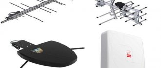
Antennas
These designs are needed to receive digital broadcasting. There are only three types of receivers, the specifics of their operation will determine the connection diagram:
- Meter range. Classic television equipment designed to receive analogue television broadcasts. Since Russia has already switched to digital, such devices are no longer relevant.
- UHF range. The device is used to receive digital channels. Structurally, it is similar to the first type antenna.
- Satellite dish. Receives signals from a satellite anywhere in the country. Therefore, the Internet and television are often used at dachas in the Moscow region where it is impossible to connect other technologies.
In sparsely populated areas, experts recommend leaving terrestrial television, at least until the second multiplex is activated.
Receiver instructions
There are many ways to configure channels on a TV receiver. It all depends on the set-top box and connection type. All existing connection methods can be divided into groups:
- Connecting to TV via a digital tuner without a receiver. In order to configure channels, it will be enough to select a TVC for each multiplex. After this, we activate automatic search and wait until the system independently selects channels. All found TV channels will be saved automatically.
- If the user is using a digital receiver, the connection will not take much time. You need to activate the AV channel on the TV receiver, and then enable automatic search on the receiver itself.
- If a satellite set-top box is connected. The operating principle of such a device is somewhat different. The receiver, regardless of the television broadcast format, perceives each television broadcast as a standard signal of a certain frequency. Users can configure channels manually, this will be faster.
Before setting up the TV receiver, you need to connect the devices in a certain sequence:
- The first step is to connect the antenna cable to the receiver.
- Then we connect the receiver to the television receiver.
- Turn on the TV and set-top box.
- We activate the power supply of the set-top box amplifier.
Connecting a stereo tuner
A stereo tuner in most cases is a device that supports stereo sound on the output device. The most commonly used cable with this is a three-prong cable. The first is responsible for video, the second and third are for the left and right audio channels L and R.
ATTENTION. Tuners with stereo support are the bulk of devices at the moment. Stereo sound can come from one channel, for example, on the right - this is the accompaniment of a TV show, and on the left - an arbitrary radio station.
To independently prevent sound interference, satellite receivers support a special function. It is implemented as a separate button or function in the Menu. The button itself is often called Audio. It allows you to fine-tune the configuration of audio channels.
How to choose a receiver
There is quite a wide variety of TV set-top box models. They all differ in their functionality and purpose. Depending on these parameters, devices are divided according to the signal standard. A separate category of equipment consists of universal devices capable of receiving any formats of digital television broadcasting. Smart set-top boxes can replace smart TVs and provide access to IPTV viewing. If you choose a receiver in an online store, you can always use the help of online consultants. Specialists will take into account the buyer’s needs and help make an informed choice.