What is an antenna amplifier and how does it work?
A TV antenna signal amplifier is a device whose task is to make the impulse resulting from the influence of an electromagnetic wave more powerful than the one initially received.
- An electromagnetic wave impinges on the conductor that makes up the TV antenna. This happens very quickly because it travels at the speed of light.
- As a result of electromagnetic induction, a current pulse appears in the conductor. However, its strength is not sufficient for correct operation.
- The pulse enters the amplifier.
- The device, using a current voltage of 5 to 12 volts, forms a “copy” of the received signal, which already has greater power.
- A tuner (internal or built into the TV) deciphers the signal, turning it into sound and video.
In addition to increasing power, the amplifier additionally filters the signal. In any antenna, in addition to the required range, there are always various unnecessary currents circulating - interference from operating electrical equipment, unnecessary stations, etc. The amplifier cuts off all unnecessary and increases the level of only useful signals.
To enhance or not
The task of the amplifier is to make sure that the level of the television signal passed from the antenna through the cable to the TV receiver becomes sufficient for the tuner to operate. Therefore, it is only necessary when the pulse power is too low.
For it to work correctly, 2 simple conditions are enough:
- presence of signal;
- proper operation of the antenna and cable.
But in the following cases, the amplifier may be harmful:
- The antenna receives a TV signal of sufficient power. Due to the specifics of the DVB-T2 standard, overamplification will lead to “artifacts” (for example, the overlapping of several programs on one another on one channel).
- The antenna receives the TV signal too poorly. To amplify, you need a high-quality original, otherwise the device will not work. There is no point in increasing the noise power.
Connection
To connect the cable to the power supply for the antenna amplifier, you need to connect the antenna cable to the plug. The first step is to prepare the cable. We retreat one and a half centimeters from the edge of the cable and make a thin circular cut,
Be careful not to damage the fine hairs of the screen under the outer layer of insulation. Remove the cut piece of insulator. Gently and evenly bend the hairs of the screen, it is better to remove the strip of foil. Stepping back 5 mm from the folded edge of the braid, make another circular cut of the inner insulator and remove it. Insert the cable under the fasteners and tighten the screws.
Please note that the metal braid must touch the bottom tinned area, otherwise power may not be supplied to the antenna. Do not allow the braid of the central core to touch, there will be a short circuit and the 12 V indicator light will not light up
If the power supply for the antenna amplifier is correctly connected to the cable, as well as the cable to the antenna amplifier, then the TV will start showing immediately after setup.
Criterias of choice
By nutrition
The amplifier is connected to the network according to one of three schemes:
- Through the antenna socket. Many digital receivers and TV receivers have the ability to supply power via a coaxial cable to the amplifier. For correct operation, simply activate this function in the settings of your TV or set-top box.
- From an external power supply. The voltage is supplied through the same coaxial cable that carries the signal. The adapter is included.
- From the built-in adapter. Such devices operate on a 220 Volt network.
By frequency range
Depending on the frequencies used in operation, amplifiers come in three types:
- Broadband. They amplify the TV signal over a wide frequency range. However, the quality of their amplification suffers. No device can be universal, uniform gain over the entire range is impossible, and degradation in quality is inevitable.
- Range. Designed to work with broadcasting of a specific frequency range and wavelength. For example, for viewing 20 channels of federal digital broadcasting, devices operating in the UHF range are suitable: this is where CETV broadcasts. Such a device will not miss any extraneous noise.
- Multi-band. This is a set of amplification blocks structurally connected into a single system. Each component is designed to work with its own broadcast area. They do not try to cover the entire range, but can amplify the TV signal in UHF (“digital”) and HF (analog transmissions). The design makes it possible to separately adjust the gain for each range.
At the installation location
Based on their installation location, amplifiers belong to one of two groups:
- Built-in. They are part of a single device - an active antenna. Externally they look like a printed circuit board inside a common casing. Their advantage is that they were originally designed for use with a specific model of television antenna. The disadvantage is that the long cable and connections on the way from the amplifier to the receiver or TV lead to weakening and a decrease in the signal level. Being outside, the amplification boards are exposed to wind, precipitation, and condensation accumulates on them due to temperature changes.
- External. Used with passive outdoor antennas. Externally, they can look different: from a separate device, similar in size to a TV set-top box, to a small block that cuts directly into the cable. Regardless of the design, external antenna amplifiers for digital TV must be connected before the input to the receiving device.
The most powerful and reliable amplifiers
Let's look at several models of television amplifiers that have earned recognition from users.
For 1-2 TVs – Gal AMP-102
A wideband amplifier allows you to work with both the meter and decimeter bands, which will be useful for residents of those areas where local analogue channels broadcast. It is distinguished by its light weight (only about 200 g) and size (resembles a long and rectangular bar connected between the antenna cable and the TV receiver socket). To operate, it uses external power - it is connected to the mains via an adapter.
- wide frequency range – from 40 to 868 MHz without gaps;
- gain adjustment from 0 to 25 dB;
- It performs well when working with both an antenna and cable TV broadcasting, so you can use it both in the city and in the country.
- The power supply gets very hot during operation.
For 2 TVs – ALCAD AL-200
This on-air amplifier simultaneously works as a splitter for two outputs. Belongs to the multi-band category: it works with MV and UHF, and the cascades are adjusted separately. This makes it possible to eliminate the unevenness of the frequency-amplitude characteristics inherent in all-wave antennas.
The model is convenient for use in a multi-room apartment or a large house, where you need to route the cable from the antenna to different points to watch TV shows on two TVs. A gain of 24 dB allows you not to be afraid of losses when transmitting a signal even to the farthest room.
- Work stability. Designed for 24/7 operation. About 15 minutes after switching on, it reaches operating mode, then it no longer heats up any more.
- Power. Users from the Moscow region note that even 80–100 km from the Ostankino TV tower, with its help, when fine-tuning the UHF antenna, all multiplexes are caught, including the third;
- Price. In terms of price-quality ratio, it has no competitors. For relatively little money, the user receives a powerful semi-professional device.
- Works only with antenna. If you try to use it to boost a cable TV signal, the results may be incorrect.
- Uneven frequency amplification. AL-200 operates in the range 40-317 and 460-863 MHz. If the broadcast falls between these values, the device will be of no use. This is precisely why it is often not suitable for cable TV.
How to properly amplify digital TV
Gain selection
Determine what level of TV signal amplification should be. The territory where DVB-T2 reception is possible is divided into 3 conventional zones:
- Close distance to the repeater (from hundreds of meters to 5–10 km). At such a distance, an amplifier is not needed; a high-quality passive antenna is sufficient.
- Average distance (15–30 km). Here the device will already be useful, but the coefficient must be selected so that in the end the signal power does not exceed the threshold value. If the TV signal is too strong, the TV or receiver will not be able to interpret it correctly and reception will not be possible.
- Long distance (30 km or more). There is no need to worry about excessive signal strength here. However, adjusting the gain will also be useful.
All distances are given for flat terrain without high-rise capital buildings. If there is signal interference, the amplifier will be useful at a closer distance. You can find out the exact distance to the nearest towers in 2 minutes using the CETV coverage map.
Also consider the gain of the antenna you are using. You need to proceed from the rule: the amplifier coefficient must be higher than that of the antenna, otherwise the device is useless.
You can find out the value in two ways:
- For factory antennas, read the instructions or look at the box. You can also look at the coefficient in online stores by searching by antenna model.
- For homemade ones, calculate using formulas from any textbook on radio engineering. They are simple, but require knowledge of the linear dimensions of the antenna, the resistance of the material from which they are made, the operating frequency and some other parameters.
Gain adjustment is carried out according to the following scheme:
- Connect the antenna at a minimum distance from the TV. If the reception is normal, then the minimum required parameters will become clear from the value of its own gain.
- Connect the antenna, located in its normal place, through the amplifier. The coefficient should be slightly greater than that of the antenna itself. If transmissions are received without interference, then no other steps are needed.
- If the TV or receiver indicates that there is no signal, increase the gain until normal reception begins.
- If digital channels stop showing, although there is a signal, or video from several programs has begun to overlap on the screen, the gain is too high and needs to be reduced.
Good video instructions for selection:
Amplifier connection
Ideally, you should use an active antenna, where the amplification unit is built into it itself. If this is not possible, place the amplifier where the antenna cable enters the room, and then extend the route to the TV.
If there are several TV receivers, intersect the wires at right angles. This will reduce the interference of cables with each other. As a result, the signal quality will improve.
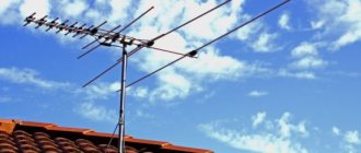
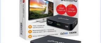
After the transition from analogue broadcasting to digital TV, users of older TV models were faced with the need to purchase special equipment. In addition to the STB set-top box, you will need an antenna, and those subscribers who previously had a decimeter design installed can also use it. Reception products differ according to several criteria. Based on the presence or absence of an amplifier, they can be active or passive.
Extending a television cable by soldering
The method of connecting a television coaxial cable using the soldering method is the cheapest and most accessible to anyone with a soldering iron and some soldering skills. If you have no experience in soldering, then you can use mine by visiting the site page “How to solder with a soldering iron using examples of soldering parts.” Using the technology given below, you can connect any shielded cables, low-frequency, high-frequency, television, with virtually no loss in the level of the transmitted signal. You can successfully connect cables of different designs, sizes and characteristic impedances.
For example, two cables with different numbers of cores in the center wire, a single-core center conductor of a television cable is connected to a stranded wire. Cables of different diameters are connected. Cables, one of which has a copper braided shield, and the other of aluminum foil.
For clarity, I demonstrated the connections of a television cable using the example of an RG 6U cable with a combined double shield made of copper braid and aluminum foil. If you have a simpler screen design, then simply skip the unnecessary description step.
By lightly pressing the knife, the outer sheath is cut lengthwise from the ends of the connected cables by 5-6 cm.
The outer sheath and shields of the connected cables are turned off.
The length of the central core of the coaxial cable with insulation is shortened to 20 mm and the central core is freed from the insulation so that a step is obtained, as shown in the photo below.
The central core and insulation of the connected television cable at the place of the step are moved away from each other to the sides so that an angle of approximately 45° is formed between them.
After tinning with solder, the central cores are brought together. To make soldering easier, you can pull the wires together by twisting them with thin tinned copper wire taken from the shielding braid.
The central cores of coaxial television cables are soldered together. Soldering must be neat and the solder must completely envelop the wires. If the solder produces icicles with sharp corners, you need to carefully grind them off with sandpaper or a file.
The soldering point of the central core of the cable is covered with insulation. Excess insulation is removed in such a way that there are practically no gaps left. To ensure tightness and impart mechanical strength to the connected coaxial cable, the junction of the insulation is covered with one turn of vinyl chloride insulating tape.
The aluminum screen is returned to its original location
Attention! On the inside, the aluminum screen of the television cable is covered with a film that does not conduct electric current. It is necessary to tuck the aluminum screen of one of the cable ends in such a way as to ensure contact of the conductive sides
If electrical contact between the screens is not ensured, the signal will not be able to reach the TV.
First, one copper shielding braid of the television cable is returned to its place, and the braid of the second end is screwed onto it. For more reliable contact, several braided conductors of a television cable can be connected by soldering and wrapped around the junction with tinned copper wire with a diameter similar to that of the braided shielding wires. But this is not necessary.
First, one outer shell of the television cable is returned to the connection point, then the shell of the second end of the cable is applied to it.
To complete the work, a couple of layers of PVC insulating tape are wound onto the television cable connection made.
The end result was a sealed, mechanically strong, and practically non-attenuating television signal level, cheap connection of a television coaxial cable by soldering.
Types of electronic boards
An amplification module is necessary for better reception if the TV is located at a distance from the nearest TV tower. Before deciding which antenna board is best, it is recommended to study all types of amplifiers and become familiar with their characteristics.
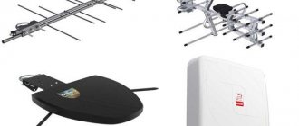
Equipment for signal amplification stands out for its diversity; an inexperienced user will quickly get confused when choosing the most suitable product. Based on functional features, active modules can be divided into several main types:
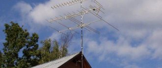
- Models operating in a wide range. They are most often used for external lattice-type structures installed on special masts.
- Devices operating within a certain range. Devices for MV devices have lost their relevance, since “digital” is available exclusively in the UHF.
- Devices configured to operate with multiple bands. They have the ability to catch signals arriving simultaneously from several sources and transmit them to one TV receiver.
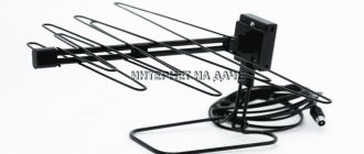
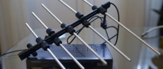
Receiving designs known as “Polish antennas” are very popular among consumers. They are usually equipped with active components of the SWA type. The TV antenna board is configured to operate in the range from 49 to 790 MHz. When choosing an active module, you should pay attention to the two most important characteristics: noise figure and gain. The first characteristic should have a minimum value, but the maximum gain does not always bring much benefit. The main thing is that the TV produces a high-quality and clear image, so you should select an amplifier taking into account specific conditions.
Based on reviews from Russian users, a rating of the most reliable and high-quality devices was compiled. Among them, LSA devices used for Locus devices stand out. The receiving structure can fail for various reasons, most often bad weather conditions become a negative factor. Using an LSA amplifier, the subscriber is able to extend the service life of receiving equipment and improve the level of the received signal.
What does signal quality depend on?
Broadcasting of digital terrestrial TV is carried out through a common repeater. Satellite-type antennas receive the signal directly from the satellite, then send it to the TV set-top box for subsequent decoding. As a result, the TV displays at least 20 standard channels with digital quality.
But this quality can change for the better and for the worse.
There are several factors that negatively affect the quality of the received signal. Namely:
- the central repeater is located far from the TV;
- the antenna used for terrestrial or satellite TV was initially selected incorrectly;
- as the signal passes, it encounters a lot of interference in the form of buildings, trees, etc.;
- there is mechanical damage to the cable;
- The orientation of the transmitter is incorrectly configured;
- this is old equipment that can no longer support and correctly display the new format;
- influenced by weather and atmospheric conditions;
- there is external interference near the antenna (especially metal objects);
- The television signal is rebroadcast to several devices at once.
The influence of one or more factors may negatively affect signal transmission. As a result, the image quality leaves much to be desired.
The situation needs to be corrected. But how exactly is a pressing question.