Television has long ceased to be perceived as a luxury. For the modern user, this technology is an indispensable thing, even despite the fact that there are a huge number of other devices. To seamlessly use modern digital television, you will need a TV that can support this technology and a special antenna device. Older model TVs will require set-top boxes. If choosing a set-top box is quite simple, then choosing an antenna may cause difficulties, because for this you need to know which antenna is needed in accordance with the parameters and type of installation. Among all amplifiers, the DVB T2 delta antenna occupies a special place.
Delta antenna for digital television
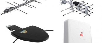
Delta TV antennas are a special device designed to receive radio signals. Such a device is used so that you can comfortably watch digital television. The manufacturer produces a fairly large number of different models. On sale you can find active-type indoor devices that are capable of not only catching signals, but also converting them.
Delta active indoor antennas have the following advantages:
- They perfectly capture and transform signals.
- Functionality is not affected by weather conditions or obstacles.
- Has increased resistance to interference.
- Indoor appliances are compact.
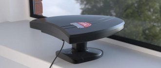
Indoor TV antenna Delta Sparrow
In specialized online stores and retail outlets you can find and profitably purchase a special Delta indoor model, which is used for digital television and is called Sparrow Plus. This is an indoor device equipped with an amplifier. The device is intended for stationary reception of digital TV signals. The frequency range of the device is MHz UHF 470-790. Even in conditions of unstable reception it is effective thanks to the built-in broadband amplifier. The amplifier is powered from a source in the set-top box. Can also function to receive radio broadcast signals. Among all the options, this one has a modern design and low weight. An indoor antenna of this type will fit perfectly into any modern interior.
Review K 331.02
Another option for indoor use. This is an indoor antenna designed to receive TV programs that are broadcast in all frequency ranges on any TV broadcast channel. This device is quite reliable, high-quality assembly and increased design safety ensure long-term operation of the device. Thanks to the built-in amplifiers, the quality of reception of any TV signals is improved. The manufacturer has equipped the device with a long cable, so it can be placed in any area of the apartment or private house. The operating frequency range is 47–230 MHz. The gain is six dB.
Dimensions
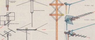
For those who want to make a copy, I provide the dimensions of the UHF and HF antennas.
All antenna dimensions are given in millimeters. The diameter of the tubes is 12 mm, the diameter of the vibrators is 4 mm, the gap between the tubes is 6 mm. At the beginning of the antenna, the tubes are secured with plastic; at the point of attachment to the mast, the tubes are soldered.
The antenna gain can be increased somewhat further by adding a reflector behind the antenna mounting device.
K131A.03: reliable amplifier for home
Delta K131A.03 is an indoor device that has all the necessary performance characteristics. It has all the capabilities to perfectly amplify the DVB-T2 signal. The device operates exclusively in the UHF range. The maximum gain is forty dB. In maximum operating mode, the antenna is capable of providing stable reception even far from the tower. This is an active model that requires power. This option may be suitable even for those apartments and houses where there is a low-quality television signal. K131A.03 is compact and lightweight. The device is made of high-strength steel.
This summer the NPP OST company introduced a new model - an active outdoor one.
But first, I would like to recall the history of antennas of this type. Well, who knows all this or perhaps is not so interesting, you can immediately scroll below and go directly to a detailed examination of H118A.F-5V .
Almost 60 years ago, in December 1958, an employee of the Institute of Communications of the USSR Ministry of Defense, Konstantin Pavlovich Kharchenko, invented his first antenna.
And then Zigzag Antenna, ” was published Beyond the Reliable Reception Zone .”
Moreover, the antenna was placed on the cover of the issue (its appearance as imagined by the artist):
And the article itself - at that time it was about an antenna for receiving 1-5 channels of the MV range:
To this day, this antenna is distinguished by its ease of manufacture and at the same time quite high performance. Unlike a single frame, a zigzag antenna has higher gain, is more broadband and is easier to match with a standard 50 or 75 Ohm coaxial cable without any additional balun-matching devices.
I note that the antenna described in the article for receiving 1-5 MV channels had a height of 3.5 m. Nevertheless, it was much easier to make structurally than, for example, a “wave channel” or a log-periodic antenna. Moreover, the higher the frequency, the smaller the dimensions, and the “eight” for reception, for example, channel 10 had a height of only 1.5 m.
And my father made such an antenna in 1969 - and it was the first television antenna not only in their village, but in the entire district. Just like the first black and white television: in their hut all day long there were residents of the surrounding villages, and everyone wanted to see the miracle - television, because no one else had a television, much less a television antenna.
The only one received was the First Program of the USSR Central Television at a distance of 90 km from the nearest tower. Of course, all this was possible only with a mast about 15 m high. And, naturally, there was no talk of any amplifiers in the village at that time. The antenna was the only and best amplifier. And now, and not only in the village, all this is also true. Because the signal is received only by the antenna itself and its design.
Soon, other still rare residents began to purchase a television, and accordingly, a simple but effective antenna was needed. And the antenna is really simple, because its manufacture required only the copper antenna cord that was widespread at that time and porcelain roller insulators (used for external electrical wiring in the house).
By the way, the second article by K.P. was published immediately next. Kharchenko “ Antenna for long-distance television reception ,” where a variant was presented with a reflector, which added more gain to the “eight” due to the narrower one-way directionality of the main lobe. And formulas were given that allow you to recalculate the antenna for any range.
Let me quote from the article:
Copyright certificate No. 138277 for an invention called “Band directional antenna” was issued to Konstantin Pavlovich Kharchenko in 1961 (according to his application dated June 16, 1960). In the same year, materials were published in the magazine “Radio” for repetition by radio amateurs [1, 2]. And subsequently, for more than 50 years, the editors repeatedly recalled these publications.
Kharchenko's zigzag (Z) antenna became a significant event among the best developments. It turned out to be uncritical to materials and dimensions during manufacturing, and has good coordination with the outgoing cable. It successfully combines multiple elements of a common-mode antenna array with a single feed point.
Despite the excellent electrical and operational characteristics, there has been no organized widespread use of zigzag antennas. In our country at that time, the internationally recognized extended and volumetric Uda-Yaga director antennas (they are also called “wave channel”) were already widely used, since industrial enterprises had mastered them in production. They, as they say now, provided the market.
However, the ease of manufacturing zigzag antennas and their attractive characteristics, with information support from the Radio magazine and amateur radio communications, made this antenna accessible even to untrained users.
I repeat, in the modern world, for Wi-Fi, 3G, 4G communications, this antenna is still the same. A few years ago I made it for Wi-Fi needs, because... Unlike other antennas, this was not difficult, and its dimensions were minimal:
But as already noted, industrial manufacturers in the USSR, and then in Russia, for some reason, ignored and are ignoring the production of household zigzag receiving antennas.
At the same time, I note that zigzag antennas have been and are being produced as transmitting antennas, and also for a wide variety of ranges:
And finally, let's proceed directly to the consideration of the antenna itself.
As already follows from the designation, the antenna is Outdoor, 1 xx - single-band UHF, active with F connector, designed for 5V , i.e., for example, from a set-top box or using the USB port of a modern TV.
The antenna comes in bright colorful packaging in branded colors and looks like a gift:
A cottage community with an antenna on the roof and a close-up of the antenna itself are shown.
Large icons indicate: gain 32 dB and 6 m cable included . Below are the logos of all channels and multiplexes.
A specific antenna modification is marked on the front flap of the box:
At the back it is noted again - gain 32 dB :
On the side is again a list of channels in the form of their logos:
On the other hand, all contact information:
On the back of the package the purpose and main technical characteristics are indicated:
As well as visual diagrams for connecting an active antenna to set-top boxes and televisions. Indicated - Date of manufacture and Quality Control Stamp.
Inside are all the antenna components, wrapped in wrapping paper:
As already noted, the antenna is equipped with 6 meters of coaxial cable:
Moreover, the cable is of high quality - . This type of cable is usually used when connecting satellite equipment:
As always, NPP OST antennas are equipped not with the usual F-connector, but with a rubber seal:
This is also more common when installing satellite equipment.
The antenna traverse is short - 326 mm. Those. very compact:
As you can clearly see, standard antenna elements produced by NPP OST are used:
Let me remind you that all elements have a protective and decorative coating with a thickness of 70-100 microns, provided with epoxy-polyester powder paints.
One half of the bracket for attaching the reflectors is welded, i.e. has a fixed position, so you don’t have to choose at what distance it’s best to fix it:
The grounding stud is also clearly visible. I will certainly note a standard, but important note from the Security Measures :
ATTENTION! It is PROHIBITED to use antennas when installed on the roof of a house or on a free-standing mast without providing reliable grounding.
This is especially true for summer cottages and houses in rural areas.
Branded antenna box with an embossed DELTA and an indication of the exact model - H118A.F-5V:
As always, there are holes for drainage at the bottom. Let me remind you that in any antenna boxes, even just from daily temperature changes day-night, condensation forms, which must be removed naturally:
If you mix up the top and bottom of any outdoor antenna, installing it with the drainage hole facing up, then literally after a few years you shouldn’t be surprised that the signal will become weaker and then disappear altogether:
Therefore, when initially installing any outdoor antenna, you should be careful.
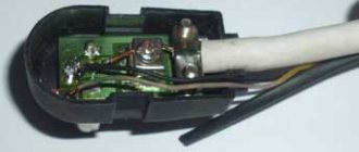
An amplifier board with an adapter cable to the F connector is installed inside:
As in the case of log-periodic antennas, if necessary, it is easy to make a passive version of a zigzag antenna by simply removing the amplifier board and connecting the cable directly to the side contacts: the central core to one, and the braid to the other lobe:
Approximate amplifier circuit. Here, as usual, is the classic two-stage circuit:
And like other manufacturers, microwave transistors are also used.
The measured current consumption is 33 mA.
Well, the heart of the antenna itself is the “figure eight”, made of a steel rod with a diameter of 4 mm:
Measured dimensions - 329x197 mm. The distance between the metal strips is 58 mm, i.e. to the size of the branded antenna box.
Measured weight is less than 100 g.
The square itself has a side of 138 mm, i.e. designed for an average frequency of approximately 543 MHz (channel 30).
Structurally, the canvas is made of two identical halves (I just showed them in different colors):
Moreover, as you can see, the joints are located in unstressed places, i.e. not on the corners.
The canvas is welded to metal strips-plates measuring 60x17 mm:
On the fastening side of the lock washers, the places are additionally tinned.
The reflectors have a span of 329 mm. Also made from rods with a diameter of 4 mm:
The ends of the reflector supports have plastic tips with holes for drainage:
The kit also includes various hardware and plastic ties for fixing the cable:
And of course, a passport with detailed assembly instructions and accessories:
It is more convenient to start the assembly by removing the cover of the antenna box, and then, as it is written: install the double frame, tightly pushing the cutouts in the strips onto the screws, and put the cover back on:
Install lock washers with external teeth and tighten the nuts:
We screw the second half of the bracket with reflectors and vibrators inside:
And this is how the antenna turned out:
Back view:
Measured dimensions - 326x329x395 mm. Measured weight: about 850 g.
And the remark from the Safety precautions is also true for any other outdoor antenna:
To protect against corrosion, it is recommended to coat all threaded connections with grease.
To configure it, it is advisable to find out which side the tower is located on. To do this, you can use the service, which allows you to determine the exact direction (azimuth) and distance to the two nearest towers - just point your mouse at your house, for example:
where the channels (frequencies) of both multiplexes on these towers and their status will be shown:
Because This antenna is outdoor, so it has more options when choosing a signal source around, incl. and from afar, for example, if only 1 multiplex is broadcast on a local tower, and somewhere further away there is a tower with 2 multiplexes. Therefore, it will be useful to find out the terrain to the far tower; for this you can use - set two points, indicate the height of your receiving antenna and transmitting antenna:
and then click the 'Build route profile' button at the bottom:
The height of the transmitting antenna can be clarified, for example, in your Consulting Support Center, on the website in the Digital TV section, and for fairly large towers there is information on the website.
And a similar tool, but even more detailed in the image of the route -. Example for a signal path from the village of Tim (10 m antenna) to Kursk (200 m tower), frequency 730 MHz:
Signal route Tim - Kursk
Moreover, it is interactive: by moving the mouse, you can evaluate the parameters in a specific place.
Of course, it is best to tune the antenna not by Automatic, but by Manual Search , selecting a specific frequency channel of your tower.
And then, slowly turning the antenna, achieve the maximum on the Quality .
On different set-top boxes/TVs this menu looks similar:
But I note: with the same antenna, different models of set-top boxes/TVs will show different values of the % Quality scale, because neither set-top boxes nor DVB-T2 TVs are, of course, measuring instruments, and this conventional scale is only needed to adjust the antenna to maximum.
And, in particular, for set-top boxes with a Novatek processor (like the one used by Elect EL-2003), for stable reception the Quality scale must be more than 40%.
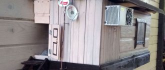
Reception parameters : loggia of the 7th floor of a residential building, surrounded by urban buildings and high-rise buildings. Near transmitter: 2 kW (area about 45 km) located at a distance of about 15 km.
Let me remind you: red is the signal path, and what is outlined in green is .
On channel 27, the Quality scale showed about 62%.
I pay attention to how the cable is laid - it is secured along the traverse with a plastic tie and is led out beyond the reflector.
And, by the way, I just now noticed that it was also manufactured by NPP OST - you can see the letters OST , and was installed several years ago.
Well, I’ll note that the antenna is well balanced - the center of gravity is in the middle of the traverse, and literally 10 cm from the center of the mast mount, i.e. minimum load.
Also checked with a long-range 5 kW transmitter operating on channel 59, located at a distance of almost 80 km:
Let's deploy the antenna:
On channel 59 - about 81%.
As you can see, the antenna is very compact, relatively speaking, for urban purposes, and does not interfere with anything.
Of course, the antenna in question is intended primarily for the middle zone, but as you can see, if the terrain is favorable, reception is possible even further.
At the same time, I note that in case of unsatisfactory reception, it is advisable to place any antenna as high as possible.
In general, speaking about heights, it is necessary to recall the reference heights for which the International Telecommunication Union calculates any types of radio, television reception and other types of communications in the range from 30 MHz to 3000 MHz.
Recommendation “Prediction method for point-to-area paths for terrestrial services in the frequency range from 30 MHz to 3000 MHz”:
Correction for the height of the receiving/moving antenna
The field strength values given by the land path curves and associated tables in this Recommendation are for a reference receiving/mobile antenna with a height equal to or greater than the height of the ground cover around the receiving/mobile antenna, R2, and 10 m.
Examples of reference heights would be 20 m for an urban area, 30 m for a dense urban area and 10 m for a suburban area.
For sea routes the nominal value of R2 is 10 m.
Those. for rural areas or the private sector in the city - 10 m, for the city (conditionally the roof of a 5-story building) - 20 m, for dense buildings (the roof of a 9-story building) - 30 m.
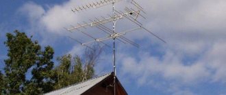
And it is at these heights that, for example, collective antennas in cities are located (i.e. only on the roof of a house):
Of course, this does not mean at all that the signal cannot be received lower, but it does mean that with weak, unstable reception it is worth striving for these heights.
And, I note that when checking numerous complaints about unsatisfactory reception in a particular locality, specialists will check the signal level at a minimum height of 10 m (and this, even for a city, is at least the level of the 3rd floor):
I repeat: all this does not mean that you cannot receive a lower signal, but if the reception is unsatisfactory, then you should think about the height. And even more so, this is the first thing to think about when it comes to a long-distance transmitter.
Let me remind you once again that the signal is not received by the amplifier, but only by the antenna itself. An amplifier is needed primarily to compensate for losses in a long cable and/or splitter.
The intrinsic gain of the Delta H118 design itself (i.e., without taking into account the built-in amplifier) smoothly increases with increasing frequency from 8.3 to 8.7 dBi. The frequency response is almost flat (blue graph):
And even if you mistakenly fix the reflectors with vibrators not inside, but outside, the gain will practically not change and will be from 8.5 to 8.3 dBi:
And only if you completely forget to install reflectors, the gain will immediately drop by 4-3 dB, but even in this hypothetical case it will still amount to significant values - from 4.1 to 5.6 dBi:
I repeat, the design of the Delta H118, despite the design with country cottages, can also be attributed to the conditional class of “city antennas” due to its compactness and at the same time having such amplification. Perhaps only panel antennas can compete with it in this regard, and it will leave other types of antennas (log-periodic, “wave channel”) behind, given the same physical limitations.
And as a result of this, the antenna has a minimum wind load - both for horizontal and vertical air flows, which is also important when installed on the wall of a high-rise city building. And for a country house this is also important.
Antenna radiation pattern in the horizontal plane:
And in the vertical plane:
Moreover, if we compare it with log-periodic antennas, then in the antenna under consideration in the vertical plane the lobe is more pressed to the ground and is comparable to a “wave channel”.
And once again I would like to note that reception interference can be created not only by modern types of communication or powerful analog transmitters, but also by faulty antennas of neighbors, and the so-called "Polish" grille:
Because people often buy an amplifier board for it with a large Ku, which is prone to self-excitation:
Well, how thin vibrators will behave when the first crow lands on them is something everyone can see with their own eyes in dacha areas and villages:
You can find out whether any of your neighbor's antennas are a source of interference by asking to temporarily unplug it from the outlet and checking your Quality scale.
We also have our own group on VKontakte: where you can also ask questions about a specific reception location and choosing a suitable antenna.
Positive: the first household zigzag antenna of industrial production in decades, very compact, but with its own gain from 8.3 to 8.7 dBi, and taking into account the built-in amplifier - up to 32 dB, +5V power supply directly from the set-top box, minimal wind load as in horizontal , and in the vertical plane, the set includes 6 meters of high-quality SAT703 cable terminated with an F-connector with a rubber seal, colorful gift packaging, and if necessary, the antenna can be easily converted into a passive one. Negative: unfortunately, like many manufacturers, the instructions there is no section for setting up the reception of a digital signal (but almost no one is interested in receiving an analog signal now, everyone wants digital).
An excellent compact antenna for the city, although of course it will also be in demand for a country house. The antenna’s own gain makes it possible to classify it as an antenna with a medium reception zone, but with favorable terrain, long-range reception is also possible. Let's hope that other domestic manufacturers will also master the production of compact zigzag antennas.
3.7/5 — (57 votes)
You can ask questions about digital television on the DVBpro forum
Author: Alexander Vorobyov, 30 Sep 2021 | Permanent link to the page:
Outdoor antennas for digital TV Delta
Antenna for digital TV Delta is a universal option for improving the television signal. Among the wide range of outdoor Delta antennas, H121F deserves attention. This is a passive device, which is of the log-periodic type. Intended for receiving digital TV, the signal of which is transmitted in the UHF range (21-60 TV channels). H121F is an oversized device and is compact. The device requires additional assembly. According to user reviews, the device is effective when used in urban environments. The manufacturer has optimally selected the ratio of sizes and gain - 6 dB. You can install the device on a balcony or loggia. Installation on external walls of houses is also allowed. The device is designed to receive and amplify the signal due to its design. The device does not require connection to a power supply network and does not contain any active amplification components. Due to the fact that the device does not contain microcircuits or transistors, it is not capable of introducing interference and noise into the received signals. The components of the H121F model are made of steel.
Specifications
| Ranges | MV, DMV |
| Gain | 20/20/20 dB |
| Protection factor | 0/0/12dB |
| Length | 830 mm |
| Weight | 1.6 kg |
| Material | steel |
| Antenna type | active |
| Amplifier power | 12 V |
The design of the antenna is quite simple and therefore it is quite accessible for repetition. The main elements that make up the antenna are: decimeter part; vibrator MV; matching board and signal amplifier. Complex elements include: a matching board and an amplifier, but you can do without them by installing an SWA type amplifier.
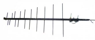
The decimeter part is a log-periodic antenna with 20 vibrators.
A log-periodic antenna (LPA) consists of two pipes located one above the other, to which the vibrator arms are attached alternately.
The cable is connected to the LPA without a special matching device as follows. A cable with a characteristic impedance of 75 Ohms is inserted into the down tube at one end and exits at the other. The cable braid is soldered to the end of the lower pipe, and the central core is soldered to the end of the upper pipe.
Depending on the wavelength of the received signal, several vibrators are excited in the antenna structure, the dimensions of which are closest to half the wavelength of the signal. At a given signal wavelength, only one trio of vibrators is excited, while the rest are detuned and do not affect the operation of the antenna. The antenna gain drops somewhat, but the bandwidth is much wider.
It is useful to know that the smoother the surface of the conductors from which the antenna is made, the higher its quality indicators (higher the quality factor).
The MV antenna is designed extremely simply - it consists of two vibrators 110 cm long, attached to the protective housing of the amplifier.
The matching board and amplifier are hidden in a sealed housing.
The balancing device is used to match meter and decimeter range antennas with an amplifier.
Model H111A-01 overview
This model has an amplifier and is intended for high-quality reception of digital television channels in the DVB-T2 format. This is an active type device that can be used outdoors. Installation can be done on a mast. Powered by power supply. It is in demand among Russian users who value it for its performance characteristics. The device receives channels 21-60. The gain is 28 dB.
Active and passive Delta models are widely used in our country. They are inexpensive and perform their functions perfectly.