Modification of the Delta N311-01 antenna
This article discusses the modification of a log-periodic antenna in order to improve the quality and range of the received digital television signal.
Antennas of this type are quite widespread due to their ease of assembly and installation, as well as good signal amplification in the decimeter range.
For the experiment, we used the Delta N311-01 antenna, passive, directional, used in an area of uncertain reception, with a range of up to 30 km from the repeater. The modification of the antenna consisted of installing a common amplifier of the SWA type on it, as well as the operability of the antenna with an amplifier without a matching device and with a factory amplifier (provided for the active antenna Delta N311-01A).
Here is the characteristics of the Delta N311-01 antenna:
| Ranges | MV and DMV. |
| Received channels | 1-5/6-12/21-69 |
| Gain | 0.5/1/8.5 dB |
| Protection factor | 0/0/12 dB |
| Material | steel |
| Location | external |
The cable can be connected to a log-periodic passive antenna (LPA) without a special matching device. A cable with a characteristic impedance of 75 Ohms is inserted into the down tube at one end and exits at the other. The cable braid is soldered to the end of the lower pipe, and the central core is soldered to the end of the upper pipe.
The modified antenna was tested at a distance of 70 km from the repeater indoors, with an antenna height from the ground of 2.5 m, the transmitter power is unknown.
Delta N311-01A antenna design
Design of the Delta N311-01A antenna
The topic of this article is inspired by the Delta N311-01A antenna (active with an amplifier) that was received for repair. The design of the antenna is such that if the vibrators for receiving the meter range are removed (which will significantly reduce its dimensions), then it can only be used as an antenna for the decimeter range.
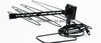
Delta N311-01A is a version of the Delta 311-01 antenna without an amplifier. An all-wave television antenna with a broadband amplifier is used in conditions of unsatisfactory reception in the VHF and UHF ranges. Receives signals from analogue and digital television broadcasting in the frequency range 48.5-890 MHz and consists of a decimeter antenna and a meter range vibrator. The antenna has uniform gain over the entire frequency range.
Vertical delta for all kV ranges
The reliable operation of any television device is largely determined by the quality of the devices used, which provide not only reception, but also amplification of terrestrial meter and UHF signals.
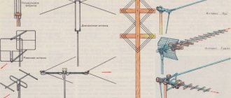
Recent advances in the field of TV information processing have made it possible to develop special methods for calculating the designs of receiving antennas, which can have a wide variety of designs. Television antenna designs
Any such antenna is usually characterized by a number of indicators, sometimes distinguished by their inconsistency and complexity of coordination. In subsequent sections, special attention will be paid to ways to overcome these contradictions.
Specifications
| Ranges | MV, DMV |
| Gain | 20/20/20 dB |
| Protection factor | 0/0/12dB |
| Length | 830 mm |
| Weight | 1.6 kg |
| Material | steel |
| Antenna type | active |
| Amplifier power | 12 V |
The design of the antenna is quite simple and therefore it is quite accessible for repetition. The main elements that make up the antenna are: decimeter part; vibrator MV; matching board and signal amplifier. Complex elements include: a matching board and an amplifier, but you can do without them by installing an SWA type amplifier.
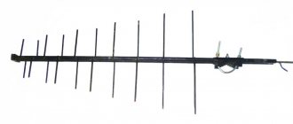
The decimeter part is a log-periodic antenna with 20 vibrators.
A log-periodic antenna (LPA) consists of two pipes located one above the other, to which the vibrator arms are attached alternately.
The cable is connected to the LPA without a special matching device as follows. A cable with a characteristic impedance of 75 Ohms is inserted into the down tube at one end and exits at the other. The cable braid is soldered to the end of the lower pipe, and the central core is soldered to the end of the upper pipe.
Depending on the wavelength of the received signal, several vibrators are excited in the antenna structure, the dimensions of which are closest to half the wavelength of the signal. At a given signal wavelength, only one trio of vibrators is excited, while the rest are detuned and do not affect the operation of the antenna. The antenna gain drops somewhat, but the bandwidth is much wider.
It is useful to know that the smoother the surface of the conductors from which the antenna is made, the higher its quality indicators (higher the quality factor).
The MV antenna is designed extremely simply - it consists of two vibrators 110 cm long, attached to the protective housing of the amplifier.
The matching board and amplifier are hidden in a sealed housing.
The balancing device is used to match meter and decimeter range antennas with an amplifier.
Features of operation
Long-term operation of Delta type antennas in the open air requires careful sealing of the input and connection areas of the cable and wire. If there are no traces of treatment with protective agents on the product, you must perform this operation yourself (taking into account the capabilities of this model).
Moisture getting inside the amplifier circuit or on the contact connections can lead to failure of the entire structure, and the cable connected to it can become completely wet in conditions of high humidity. Possible consequences of these operational violations are a short circuit in the power circuits and complete burnout of the entire electronic part of the device.
Additional Information. The only correct way out of this situation is to completely replace the soaked cable along with the antenna plug.
Drying a wet cable product is unacceptable, since over time it will still fail due to the presence of internal elements damaged by corrosion (braided shielding, in particular).
In the event of a noticeable deterioration in the quality of reception on all or several television channels (or its complete loss), you should disassemble the plug and make sure that the wiring of the central core and braid are in good condition. If serious violations are detected, it is necessary to cut off the cable near the damaged connector and make a new contact connection in the form of an antenna plug.
In conclusion, we note that to independently assemble a Delta-type antenna, you need an appropriate level of training and skills to work with devices of this class. There is not enough professional data for this on the Internet, since all the information presented in the sections on this topic concerns mainly amateur radio samples.
Dimensions
For those who want to make a copy, I provide the dimensions of the UHF and HF antennas.
All antenna dimensions are given in millimeters. The diameter of the tubes is 12 mm, the diameter of the vibrators is 4 mm, the gap between the tubes is 6 mm. At the beginning of the antenna, the tubes are secured with plastic; at the point of attachment to the mast, the tubes are soldered.
The antenna gain can be increased somewhat further by adding a reflector behind the antenna mounting device.
28 Comments on “Delta N311-01A antenna design”
There is a Delta-311 without an amplifier on the wall at the level of the second floor windows. Used only to receive TV signals. Reception of the current 20 digital channels is excellent. But on the roof they started replacing the old slate covering with corrugated sheeting, the cornice has become smaller and precipitation is falling on the MV vibrators of the antenna. At subzero temperatures they will likely be covered in snow and ice, and if ice and snow falls on them from the roof, they can damage the mount to the wall, or even tear out the antenna. Is it possible to simply unscrew the MV vibrators from the antenna without getting inside, if the antenna does not have an amplifier? For package digital TV, you only need UHF.
Source
Connection procedure
UHF antenna
To understand how to properly connect Delta to a television receiver, please note that this procedure is practically no different from connecting any other device of a similar purpose.
In order to connect it correctly, you first need to cut the mating end of the cable wire for a contact connector or soldering. This operation is necessary in order to arrange it in the form of a standard plug connector, which will be used to connect to the input jack of the receiver.
If a model with a built-in amplifier is used, its design must include another wire designed to connect the delta antenna to the power supply adapter (see the figure below).
Connection diagram
Important! When connecting a cable to a plug, under no circumstances should a short circuit be allowed between the screen braid and the thin central core.
When carrying out the described procedures, it is recommended to follow the instructions for designing television connectors, which should contain a connection diagram.
How to convert a delta antenna to a digital one. About cable soldering
The topic of this article is inspired by the Delta N311-01A antenna (active with amplifier) that came in for repair. The design of the antenna is such that if the vibrators for receiving the meter range are removed (which will significantly reduce its dimensions), then it can only be used as an antenna for the decimeter range.
Delta N311-01A is a version of the Delta 311-01 antenna without an amplifier. An all-wave television antenna with a broadband amplifier is used in conditions of unsatisfactory reception in the VHF and UHF ranges. Receives signals from analogue and digital television broadcasting in the frequency range 48.5-890 MHz and consists of a decimeter antenna and a meter range vibrator. The antenna has uniform gain over the entire frequency range.
The design of the antenna is quite simple and therefore it is quite accessible for repetition. The main elements that make up the antenna are: decimeter part; vibrator MV; matching board and signal amplifier. Complex elements include: a matching board and an amplifier, but you can do without them by installing an SWA type amplifier.
The decimeter part is a log-periodic antenna with 20 vibrators.
A log-periodic antenna (LPA) consists of two pipes located one above the other, to which the vibrator arms are attached alternately.
The cable is connected to the LPA without a special matching device as follows. A cable with a characteristic impedance of 75 Ohms is inserted into the down tube at one end and exits at the other. The cable braid is soldered to the end of the lower pipe, and the central core is soldered to the end of the upper pipe.
Depending on the wavelength of the received signal, several vibrators are excited in the antenna structure, the dimensions of which are closest to half the wavelength of the signal. At a given signal wavelength, only one trio of vibrators is excited, while the rest are detuned and do not affect the operation of the antenna. The antenna gain drops somewhat, but the bandwidth is much wider.
It is useful to know that the smoother the surface of the conductors from which the antenna is made, the higher its quality indicators (higher the quality factor).
The MV antenna is designed extremely simply - it consists of two vibrators 110 cm long, attached to the protective housing of the amplifier.
The matching board and amplifier are hidden in a sealed housing.
The balancing device is used to match meter and decimeter range antennas with an amplifier.
Delta setting
For more than a week now I have been struggling with setting the inclined delta of the 40th range. So far the result is not very good, the minimum SWR is about 3. The design turned out something like this. The top of the delta is located at a height of approximately 13m on a metal mast, the upper corner at a distance from the mast is approximately 20-30cm. The mast stands next to the elevator technical structure, about 2 meters high, and one of the corners is hooked onto a massive metal ventilation knob, also about 2 meters high, making a total of about 4 meters from the roof. And the third corner is hooked onto the edge of the roof at a height of about a meter. I adjusted it, trying to find the minimum SWR, adjusting the length of the blade, lengthening or shortening it, moving the cable connection point up and down from the lowest corner and changing the cable itself 50 or 75 Ohm. Changing the length by literally 20cm radically changes the whole picture. The minimum SWR results obtained were about 2.2. I tried to improve it, but it didn’t work, everything only got worse, as many as two minimums appeared at about plus or minus 500 kHz, the upper one being sharper. Therefore, the idea came to mind to try to make the setup more systematic. I want to say right away that the only instrument available is an SWR meter and the transmitter operates in a wide frequency range. First, I determine the frequency at which the current in the antenna is maximum. Now it is approximately 7320 kHz. Obviously, the antenna length needs to be increased by about 120cm in order to shift this maximum to approximately the middle of the range. And then, without changing the length of the web, changing the cable connection point or one of the suspension points, try to obtain a minimum SWR. How do you see this technique?
- Share Share this post via
- Digg
- Del.icio.us
- Technorati
- Post on VKontakte
- Post on Facebook
- Post to MySpace
- Post in
- Post to LiveJournal
- Post to Google
- Post to Yahoo
- Post to Yandex.Bookmarks
- Post to Links@Mail.Ru
- Reddit!
The input impedance of your delta is about 106 ohms. It is consistent with a 50 Ohm transceiver cable with a characteristic impedance of 75 Ohms and a length of 1/4 lambda (taking into account the shortening factor): 75 * 75/50 = 112.5 Ohms. The length of the delta blade is usually slightly more than 1 lambda; for 40 meters, 42.5 meters is often recommended. But the exact size depends on the wire you use. The feed point (for vertical polarization) is located at a distance of 1/4 of the length from the top corner.
As an alternative, you can match through a transformer on a ferrite ring or a low-pass step down L-shaped LC circuit (essentially a tuner with fixed ratings).
Dimensions
For those who want to make a copy, I provide the dimensions of the UHF and HF antennas.
All antenna dimensions are given in millimeters. The diameter of the tubes is 12 mm, the diameter of the vibrators is 4 mm, the gap between the tubes is 6 mm. At the beginning of the antenna, the tubes are secured with plastic; at the point of attachment to the mast, the tubes are soldered.
The antenna gain can be increased somewhat further by adding a reflector behind the antenna mounting device.
Attention! Outdoor DVB-T2 antennas can be found in the section Outdoor antennas for digital television
Features of Delta antennas
In most versions, Delta television antennas are supplied with all components
for their installation or partially assembled, so you will not have any problems with installing such a television antenna. In conditions where it is necessary to install the Delta antenna at a certain height, for example, in a country house, masts of the required length are used; they are purchased separately. You can select these additional components for the antenna in our store. You can choose the “Delta” television antenna that is right for you after familiarizing yourself with its characteristics in our company’s catalog.
We are so accustomed to the flow of information that without it we feel insecure. That’s why, outside the city, having more or less equipped a house, the first thing that appears is a television. And for it to work in rural areas, you need a television antenna for your dacha. It is selected depending on the location of the nearest repeater - television tower and the type of television signal that you will “catch”.
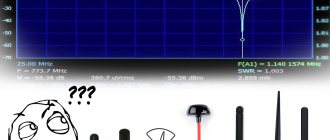
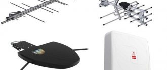
Today there are several types of signals, and accordingly, the same number of types of antennas:
Antenna connection
The photo shows an option when the amplifier is installed correctly, and an option when it is incorrect
Wrong Correct
The amplifier has contact pads to which the antenna waveguides are connected. If the amplifier is installed incorrectly, its input remains unconnected; naturally, the signal from the antenna does not reach the amplifier input, and the antenna does not work. You can spend time installing the antenna, but the result will be negative, you will have to redo the work, and you may need to replace the amplifier, since very often, if connected incorrectly, SWA amplifiers fail. We will assume that the antenna assembly has been completed and everything has been done correctly.