Another homemade product for those who are bored at home
I needed a couple of antennas for digital, in places with “not the best reception”... I went shopping (this was before self-isolation - if it’s relatively budget-friendly, then it’s complete G. The more expensive one looks decent, but how it works is questionable.
I decided to make something homemade. It was somehow awkward to “twist” an antenna from a piece of cable (although rumor has it it works) - I wanted something simple, but more decent and advanced
In fact, the one I made is not radically more complicated, but somehow more “solid” or something. And the results of its testing were very encouraging, so I decided to sketch out a short description of what and how, in case someone else finds it useful 
... even if my street cats have a “normal” antenna on their house, what can you do without an antenna?!
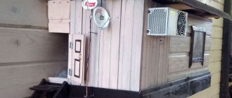
In the places described, I previously used home-made broadband log-periodic antennas, probably since the “beginning of perestroika.” They worked well in analog and not only on UHF, but “for some reason, digital was too tough for them.” I didn’t really delve into the essence of the reasons, I removed them and began to think about what to replace them with. Here is one of them, waiting for a place in the trash
A little history
In the early 60s of the last century, our compatriot Kharchenko K.P. developed a simple flat zigzag antenna with good characteristics.
Copyright certificate No. 138277 for an invention called “Band directional antenna” was issued to Konstantin Pavlovich Kharchenko in 1961 (according to his application dated June 16, 1960). In the same year, materials were published in the magazine “Radio” for repetition by radio amateurs.
The antenna is not critical to materials and dimensions during manufacturing, has a simple good match with the reduction cable, and it successfully combines multiple elements of a common-mode antenna array with a single feed point.
Theory and calculations
The described antenna, in theory, has a horizontal “figure-of-eight” radiation pattern and a relatively high gain, which can be further increased by using a reflector/reflector.
To obtain maximum gain on all channels, it is necessary to make an antenna approximately in the middle of the range between the multiplexes used.
Finding (for calculations) the frequencies of multiplexes used in your region is easy,
for example, a request like “dvb-t2 channel frequencies” + “Krasnodar”
I found something like this:
The middle, between “my” two multiplexes, is 700 MHz - we will calculate the antenna at this frequency.
As a basis for calculating the dimensions of the antenna, we take the drawing of its author
Calculate the wavelength: λ = 300 / f [m]
300/700 = 0.428m, approximately 43cm length of each side of the rhombus
λ/4
=43/4= 10.75
The total length of the material we need (11cm*8=88cm) is less than a meter. The distance between the reduction contacts, where we will solder the cable, is 10-12mm (the standard value for this antenna for frequencies below 900 MHz).
I will make a simple antenna, without a reflector, however, to further increase the gain of this antenna, it is quite possible to install it behind it
for example, from a metal mesh/grill, foil material or simply a metal plate. Its dimensions should be approximately 20 percent larger than the dimensions of the antenna and it should be located at a distance of ƛmax/7. For my case: wavelength (channel 39) 300/618, it turns out...49/7= that is, about 7cm
For those who are too lazy to do the calculations themselves
— you can use an online calculator, the results will differ only slightly from those I received. Here, for example, this one - here you immediately enter the frequencies of two multiplexes and get the dimensions of the antenna (without a reflector) Or another option, with a reflector - I really want to note that in the second option a slightly different calculation option is used, different from the author’s. An antenna with angles other than 90° is assumed and the reflector distance is calculated as λ/8
To make the antenna sheet, it is recommended to use aluminum or copper (copper is easily soldered) with a diameter of 3 mm and higher - the larger the diameter, the more broadband the antenna is. You can use tubes; the thickness of the walls is not important, since only the surface of the material is used (in fact, you can wrap any dielectric with foil to obtain the required material). However, in my opinion, the easiest way is to buy a meter of large-gauge copper wire at an electrical supply store.
Simple for Wi-Fi - from a metal can
An antenna for receiving a Wi-Fi signal can also be made from improvised means - from a tin can. This TV antenna can be assembled in half an hour (if you don't rush).
The jar should be made of metal, with smooth walls. Tall and narrow canning jars work great.
If you plan to install a homemade antenna on the street, you should find a jar with a plastic lid. The cable is an antenna, coaxial, with a resistance of 75 Ohms.
Photo of a simple TV antenna - below:
Wi-Fi transmitters operate at a frequency of 2.4 GHz with a wavelength of 124 mm. It is advisable to choose a jar so that its height is at least 3/4 of the wavelength. For this case, it is better that it be more than 93 mm. The diameter of the can should be as close as possible to half the wavelength - 62 mm for a given channel. There may be some deviations, but the closer to the ideal, the better.
Antenna assembly
Let's remove the insulation from a piece of wire one meter long.
I got a wire with a diameter of 4.5mm
The tools you will need are a vice and a hammer. Measure approximately 11cm each and bend at an angle of 90°
The end result is to get such a “geometric” figure
We cut off the excess and solder the ends. It should look something like this...
Solder the cable as shown in the photo.
We lay the cable along one side of the square and secure it with clamps. This arrangement of the cable is necessary for its coordination (there are different opinions, not everyone agrees with this statement).
When using a reflector, the antenna sheet at the extreme points of the squares can also be secured using metal stands, for example, soldered onto the remains of the same copper wire - there are points with zero potential (highlighted in green). In other places, fastening is allowed only through a dielectric.
Tests
And finally, a performance check and a rough
assessment of the quality of the resulting antenna.
In fact, everything is simple with the test - turn it on, it works! And to evaluate whether the game was “worth the candle,” let’s compare the parameters of the received signal from the manufactured antenna with the one I’m already using at the dacha, with a declared gain of 11dBi
The antenna is installed in the attic of a country house, at a distance of approximately 16 km from the tower.
Signal level: factory stationary antenna on the left / homemade on the right
At first glance, the difference is only 1% (95 versus 94) - but this is not a completely correct comparison, since my external antenna is connected through a splitter, which further weakens the signal.
Preparatory stage
You need to start any work by finding out what materials and tools will be needed for installation.
In order to assemble a Z-antenna for digital TV with your own hands at home, you will need the following elements:
- Wires. It is advisable to use copper or aluminum wire with an average diameter of 3 mm. If there is no wire at hand, but there is a tube or strip that conducts current, made of a similar material, then you can bend these elements.
- Coaxial cable.
- Plug.
- Fastening for the structure. It depends on the location of the future device. For example, on the top floors of a high-rise building, such an installation can be hung on a window or on curtains. If the device will be used in the private sector, then it is better to attach it to a pole on the roof.
Don't forget to prepare a number of devices
In addition to the above materials, you must have the following tools:
In 90% of cases, such materials and tools end up at home, collecting dust on the shelves. After they have been found and collected in one place, you can begin to construct.
First, you need to calculate the required length of wire, measure the required piece and bend it, strictly observing the dimensions.
It is recommended to take a wire 1 meter 12 centimeters long, which is then cut to the required length and bent.
Read also: Wiring sockets in the kitchen distribution diagram
After which two ends should form. It is better to clean them at a distance of 1-2 centimeters. Loops are made at the ends, which are fixed together.
Important! All angles should be approximately 90 degrees Celsius.
The joints need to be soldered. After this, the central core is soldered to one joint, and the braid is soldered to the remaining joint.
The end result of this stage should be a finished square.
Assessing the performance of the antenna
Let's try to make a more correct comparison by connecting through the splitter input.
Well, in addition, for clarity, let’s add the number of participants List of antennas taking part in the comparison:
1. External antenna Funke BM 4551 external long-range,
declared gain, from some sources (bought at Yulmart), up to 16dB
2. There is an old UHF loop antenna, from TV Electronica 313d, I must say, despite its simplicity, it’s a very good antenna, that’s why it’s been preserved
3. I went to the store and bought for comparison in the review one of the cheapest, such as a symmetrical vibrator (100% the most purchased by pensioners, due to the low price).
I will carry out all “measurements” at one point, located as close as possible to the external antenna - its location was experimentally selected based on the maximum signal, so we can say that the conditions are approximately the same
So, we have already seen the signal level from the external antenna at 95% (at the time of current measurements it showed 94%), we take it as a standard. All comparisons are made by connecting antennas to the input on the splitter, to which an external antenna is usually connected.
Loop antenna, from Electronics 82% on 39 multiplex and 66% on 60
Budget with “horns” - 62%/38% (on the verge of losing the broadcast)
Double square - 92% on both multiplexes, about a couple of percent less than the external one
Out of curiosity, I decided to check the work of the reflector, which is easy to make from any metal mesh, plate or even foil... It REALLY works noticeably! The level rose to 96%!, which is even higher than the stationary one, with a declared gain of 11dB.
The most interesting thing is the object that I used as a reflector!
There was no foil in the house; the only thing available with a metal surface of the required size was... a laptop cover (I have a metal case). But the main thing is the result! It’s clear that I’m not going to “tie” the laptop to the antenna, and its amplification is enough for me without a reflector
Recommendations for use
The Kharchenko antenna has been actively used in households for more than one year, therefore, in order to ensure the longevity of its operation, it is recommended to periodically look after and care for it.
There are a number of recommendations
Here are some simple tips for long-term operation of the device:
- The connection between the cable and the antenna frame can be protected from external influences by wrapping it with regular electrical tape. However, this method is not permanent. It would be better to fill everything with glue.
- For the housing, some people use regular bottle caps or plastic jar caps. Recesses are made in the right places for normal cable exit. After which, everything is filled with a special sealing compound.
- When using an amplifier for a Kharchenko antenna for digital TV, the second square is not necessary.
- Also, for additional reinforcement, a double biquad is constructed. Everything is mounted in the same way as the regular version, but instead of the corners there are additional squares. As a rule, there are an even number of them. Their calculation is not necessary, because they must be similar in size to the main biquadrat.
That’s it, Kharchenko’s DIY television antenna is ready for using digital TV.
Conclusion:
I can confidently recommend repeating it!
Simple, “cheap and tasty”... One of the simplest, indoor antenna mounts... with ordinary suction cups - if you’re lucky with the direction to the television center
The next antenna "recommended for repetition" is... log periodic
“Crazy hands” were with you. Good luck and good mood to everyone! ☕