Another homemade product for those who are bored at home
I needed a couple of antennas for digital, in places with “not the best reception”... I went shopping (this was before self-isolation - if it’s relatively budget-friendly, then it’s complete G. The more expensive one looks decent, but how it works is questionable.
I decided to make something homemade. It was somehow awkward to “twist” an antenna from a piece of cable (although rumor has it it works) - I wanted something simple, but more decent and advanced
In fact, the one I made is not radically more complicated, but somehow more “solid” or something. And the results of its testing were very encouraging, so I decided to sketch out a short description of what and how, in case someone else finds it useful 
... even if my street cats have a “normal” antenna on their house, what can you do without an antenna?!
The wire is not all finished yet, now we’ll assemble something!
In the places described, I previously used home-made broadband log-periodic antennas, probably since the “beginning of perestroika.” They worked well in analog and not only on UHF, but “for some reason, digital was too tough for them.” I didn’t really delve into the essence of the reasons, I removed them and began to think about what to replace them with. Here is one of them, waiting for a place in the trash
A little history
In the early 60s of the last century, our compatriot Kharchenko K.P. developed a simple flat zigzag antenna with good characteristics.
Copyright certificate No. 138277 for an invention called “Band directional antenna” was issued to Konstantin Pavlovich Kharchenko in 1961 (according to his application dated June 16, 1960). In the same year, materials were published in the magazine “Radio” for repetition by radio amateurs.
The antenna is not critical to materials and dimensions during manufacturing, has a simple good match with the reduction cable, and it successfully combines multiple elements of a common-mode antenna array with a single feed point.
Theory and calculations
The described antenna, in theory, has a horizontal “figure-of-eight” radiation pattern and a relatively high gain, which can be further increased by using a reflector/reflector.
To obtain maximum gain on all channels, it is necessary to make an antenna approximately in the middle of the range between the multiplexes used.
Finding (for calculations) the frequencies of multiplexes used in your region is easy,
for example, a request like “dvb-t2 channel frequencies” + “Krasnodar”
I found something like this:
The middle, between “my” two multiplexes, is 700 MHz - we will calculate the antenna at this frequency.
As a basis for calculating the dimensions of the antenna, we take the drawing of its author
Calculate the wavelength: λ = 300 / f [m]
300/700 = 0.428m, approximately 43cm length of each side of the rhombus
λ/4
=43/4= 10.75
The total length of the material we need (11cm*8=88cm) is less than a meter. The distance between the reduction contacts, where we will solder the cable, is 10-12mm (the standard value for this antenna for frequencies below 900 MHz).
I will make a simple antenna, without a reflector, however, to further increase the gain of this antenna, it is quite possible to install it behind it
for example, from a metal mesh/grill, foil material or simply a metal plate. Its dimensions should be approximately 20 percent larger than the dimensions of the antenna and it should be located at a distance of ƛmax/7. For my case: wavelength (channel 39) 300/618, it turns out...49/7= that is, about 7cm
For those who are too lazy to do the calculations themselves
— you can use an online calculator, the results will differ only slightly from those I received. Here, for example, this one - here you immediately enter the frequencies of two multiplexes and get the dimensions of the antenna (without a reflector) Or another option, with a reflector - I really want to note that in the second option a slightly different calculation option is used, different from the author’s. An antenna with angles other than 90° is assumed and the reflector distance is calculated as λ/8
To make the antenna sheet, it is recommended to use aluminum or copper (copper is easily soldered) with a diameter of 3 mm and higher - the larger the diameter, the more broadband the antenna is. You can use tubes; the thickness of the walls is not important, since only the surface of the material is used (in fact, you can wrap any dielectric with foil to obtain the required material). However, in my opinion, the easiest way is to buy a meter of large-gauge copper wire at an electrical supply store.
From beer cans
A slightly more complex antenna is assembled from empty cans of beer or other drinks. It is quite effective (the aluminum from which they are made is an excellent conductor), but it requires carefully measuring the distance between the can vibrators, as well as connecting them in the correct sequence.
In general terms, this process looks like this:
- An even number of cans is taken (minimum two, maximum - as much as desired; the more, the more powerful).
- Using a drill, holes are drilled into the cans to allow wire (preferably copper or aluminum) to pass through, which will connect them to each other. You don’t have to drill, just use self-tapping screws that will attach the vibrators to a wooden or plastic bracket (for example, a popular option is when the cans are mounted on a wooden or plastic hanger). In this case, the conductor can be clamped with a self-tapping screw, which will act as a contact.
- Banks are connected according to a strict scheme.
- At the junction of the two ends of the wire, a cable is connected (for example, using a standard fastening device from an old antenna, soldering, etc.).
- Easy to assemble. All materials can be found literally under your feet, with the exception of coaxial cable and fasteners.
- Efficiency. If the terrain allows, you can receive a TV signal from it from a distance of up to 50 km.
- To make full use of the power of the receiving device, you need a fairly accurate calculation of the size of the vibrators. However, this is the problem with all homemade products.
- Large windage in the street version. Empty and light vibrators will rotate under the influence of the wind if they are not properly secured.
Antenna assembly
Let's remove the insulation from a piece of wire one meter long.
I got a wire with a diameter of 4.5mm
The tools you will need are a vice and a hammer. Measure approximately 11cm each and bend at an angle of 90°
The end result is to get such a “geometric” figure
We cut off the excess and solder the ends. It should look something like this...
Solder the cable as shown in the photo.
We lay the cable along one side of the square and secure it with clamps. This arrangement of the cable is necessary for its coordination (there are different opinions, not everyone agrees with this statement).
When using a reflector, the antenna sheet at the extreme points of the squares can also be secured using metal stands, for example, soldered onto the remains of the same copper wire - there are points with zero potential (highlighted in green). In other places, fastening is allowed only through a dielectric.
"Butterfly"
A “butterfly” is a name given to a relatively simple but effective short-wave antenna for receiving digital television due to its specific shape: vibrator conductors fan out from the mounting axis, like the wings of a real insect.
For production you will need:
- thin board or plywood measuring approximately 550 by 70 mm and about 5 mm thick;
- about 4 m of copper or, worse, aluminum wire with a cross-section of 4–6 mm;
- self-tapping screws;
- screwdriver or screwdriver;
- stripping knife;
- soldering iron with solder and flux paste;
- ruler for marking;
- wire cutters or pliers;
- pencil for marking the board;
- 75 Ohm plug;
- F-connectors for connection.
Manufacturing looks like this:
- The dimensions of the vibrators and the distance between them are calculated. The average length can be considered 37.5 cm.
- The wires are cut according to the calculated dimensions. Eight conductors will be required.
- The middle of each conductor is stripped 2 cm.
- Each wire is bent in an arc so that there is at least 7.5 mm between the ends. Instead of two wires, you can use a sheet of metal cut in the shape of a triangle, then this antenna will be closer to the design patented in 1938 under the name Butterfly dipole.
- Two wires about 43 cm long are cut off. They are stripped in those places where they will be attached to the board.
- All wires are connected to each other according to the connection diagram.
- The antenna outputs are soldered into the plug.
- A 75 Ohm adapter wire is connected to the plug.
- A cable is connected to the adapter.
- The antenna is adjusted for reception and mounted in a suitable position.
- ease of manufacture;
- efficiency.
- relatively low gain.
Tests
And finally, a performance check and a rough
assessment of the quality of the resulting antenna.
In fact, everything is simple with the test - turn it on, it works! And to evaluate whether the game was “worth the candle,” let’s compare the parameters of the received signal from the manufactured antenna with the one I’m already using at the dacha, with a declared gain of 11dBi
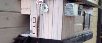
The antenna is installed in the attic of a country house, at a distance of approximately 16 km from the tower.
Signal level: factory stationary antenna on the left / homemade on the right
At first glance, the difference is only 1% (95 versus 94) - but this is not a completely correct comparison, since my external antenna is connected through a splitter, which further weakens the signal.
Log-periodic
Finally, you can make your own home antenna using a classic log-periodic design.
Main design features:
- vibrators of variable length are mounted on a common axis;
- the length of the working elements should not go beyond the limits required for the UHF range, but at the same time the change in their value obeys the logarithmic law;
- The location of the vibrators depends on the period of the waves that this device is designed to receive. This is where its name comes from.
Here we just recall the key points:
- Two thick tubes are taken as axes for the vibrators and a number of receiving elements - solid, made of thick wire, or hollow, made of thin tubes. There is not much difference: at the frequencies where digital television operates, the current still mainly runs along the surface of the conductor. Instead of thick tubes for axles, you can use foil PCB plates.
- The size of the rods and vibrators, as well as the distance between them, is calculated.
- The left and right receiving channels are mounted separately on the corresponding rods.
- The rods are connected by a jumper.
- A coaxial cable is connected.
- The second end of the feeder goes to the set-top box or antenna socket of the digital TV.
- Very wide range - about 10 times greater than other UHF devices.
- In terms of gain, it is equivalent to a wave channel of 3–4 elements, but the antenna is more compact and more technologically advanced.
- Versatility. Suitable not only for television, but also for mobile communications, Wi-Fi, etc. The only question is the size of the elements.
- Difficult to manufacture. It is necessary to maintain both the length of the vibrators and the distance between them.
- The calculation, unlike the above constructions, is very difficult to do on a piece of paper - you need to find a solution to about half a dozen integral equations. Therefore, the only option for a DIYer is to use the online calculator in the article above.
Today, terrestrial television is the most common among users. It works by collecting radiation from the broadcaster to the receiver. Due to a number of factors, the antenna may fail, and it is not possible to install a new one at the moment.
In this case, you can make a homemade antenna for digital television, which will receive a television signal no worse than factory devices. This article will discuss the manufacture of different types of antennas for digital TV with your own hands under specific conditions, for temporary and permanent use.
Assessing the performance of the antenna
Let's try to make a more correct comparison by connecting through the splitter input.
Well, in addition, for clarity, let’s add the number of participants List of antennas taking part in the comparison:
1. External antenna Funke BM 4551 external long-range,
declared gain, from some sources (bought at Yulmart), up to 16dB
2. There is an old UHF loop antenna, from TV Electronica 313d, I must say, despite its simplicity, it’s a very good antenna, that’s why it’s been preserved
3. I went to the store and bought for comparison in the review one of the cheapest, such as a symmetrical vibrator (100% the most purchased by pensioners, due to the low price).
I will carry out all “measurements” at one point, located as close as possible to the external antenna - its location was experimentally selected based on the maximum signal, so we can say that the conditions are approximately the same
So, we have already seen the signal level from the external antenna at 95% (at the time of current measurements it showed 94%), we take it as a standard. All comparisons are made by connecting antennas to the input on the splitter, to which an external antenna is usually connected.
Loop antenna, from Electronics 82% on 39 multiplex and 66% on 60
Budget with “horns” - 62%/38% (on the verge of losing the broadcast)
Double square - 92% on both multiplexes, about a couple of percent less than the external one
Out of curiosity, I decided to check the work of the reflector, which is easy to make from any metal mesh, plate or even foil... It REALLY works noticeably! The level rose to 96%!, which is even higher than the stationary one, with a declared gain of 11dB.
The most interesting thing is the object that I used as a reflector!
There was no foil in the house; the only thing available with a metal surface of the required size was... a laptop cover (I have a metal case). But the main thing is the result! It’s clear that I’m not going to “tie” the laptop to the antenna, and its amplification is enough for me without a reflector
Triple square
The triple square, also known as the Sotnikov antenna (non-standard radio devices are usually named after the name of the inventor or popularizer), consists of three square frames of variable perimeter:
- directors;
- vibrator - it is from it that the received signal is removed;
- reflector.
This antenna is a development of the principles inherent in the design of the wave channel, but it is much simpler to manufacture. Outwardly, it looks like three squares gradually decreasing in size, mounted on common crossbars so that their axis faces in the direction of the signal source.
In short, it is assembled from steel or copper wire as follows:
- Three main squares and jumpers between them are bent. If necessary, you can immediately bend the entire zigzag assembly according to the attached drawing.
- The joints are soldered together.
- The stripped end of a 75 Ohm coaxial cable is soldered into the split of the vibrator (where the wire ends are connected).
- High sensitivity. This is a good long-range device for receiving a weak signal from a long distance.
- Manufacturability. If you bend it from a single piece of wire, then soldering will only be needed to connect the cable and joints.
- It is possible to connect an amplifier, which turns the structure into an active antenna, ideal for a summer house or country house.
- Not the best radiation pattern. Even a slight bend in the wire leads to losses in the received signal power.
- Extremely narrow focus. A triple square covers no more than 10 channels according to the old layout, so if the multiplexes differ greatly in frequency, you will either have to make two antennas (and solve matching problems) or sacrifice sensitivity.
- To get all the benefits from the range of this antenna, you need an accurate calculation (ideally down to the millimeter).
Conclusion:
I can confidently recommend repeating it!
Simple, “cheap and tasty”... One of the simplest, indoor antenna mounts... with ordinary suction cups - if you’re lucky with the direction to the television center
The next antenna "recommended for repetition" is... log periodic
“Crazy hands” were with you. Good luck and good mood to everyone! ☕