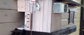
Another homemade product for those who are bored at home
I needed a couple of antennas for digital, in places with “not the best reception”... I went shopping (this was before self-isolation - if it’s relatively budget-friendly, then it’s complete G. The more expensive one looks decent, but how it works is questionable.
I decided to make something homemade. It was somehow awkward to “twist” an antenna from a piece of cable (although rumor has it it works) - I wanted something simple, but more decent and advanced
In fact, the one I made is not radically more complicated, but somehow more “solid” or something. And the results of its testing were very encouraging, so I decided to sketch out a short description of what and how, in case someone else finds it useful 
... even if my street cats have a “normal” antenna on their house, what can you do without an antenna?!
The wire is not all finished yet, now we’ll assemble something!
In the places described, I previously used home-made broadband log-periodic antennas, probably since the “beginning of perestroika.” They worked well in analog and not only on UHF, but “for some reason, digital was too tough for them.” I didn’t really delve into the essence of the reasons, I removed them and began to think about what to replace them with. Here is one of them, waiting for a place in the trash
A little history
In the early 60s of the last century, our compatriot Kharchenko K.P. developed a simple flat zigzag antenna with good characteristics.
Copyright certificate No. 138277 for an invention called “Band directional antenna” was issued to Konstantin Pavlovich Kharchenko in 1961 (according to his application dated June 16, 1960). In the same year, materials were published in the magazine “Radio” for repetition by radio amateurs.
The antenna is not critical to materials and dimensions during manufacturing, has a simple good match with the reduction cable, and it successfully combines multiple elements of a common-mode antenna array with a single feed point.
TV antenna made from tin cans
To assemble a simple DIY antenna for digital TV, use coaxial wire and several aluminum or tin cans. It is also advisable to prepare a small plastic pipe. The choice of material for the base is obvious - a plank made of wood.
Only tin or aluminum cans can provide signal reception. Glass or plastic is suitable for this.
There is only one requirement for the material - the inner surface must be smooth, not ribbed. Anyone can design a TV antenna by following simple step-by-step instructions:
- First, wash the jars thoroughly and then wait until they dry.
- Treat the end of the antenna wire.
- Remove the insulation from the central core, and then twist the braid.
- You have two conductors that need to be attached to the cans.
- The conductors can be soldered if desired, if you have the necessary tool at hand. An alternative option is to secure the conductors with self-tapping screws.
- Twist loops at the ends of the conductors. You need to insert self-tapping screws into them, and only then secure them to the cans.
- Use fine-grit sandpaper to thoroughly clean the metal surface of the cans, removing the paint.
- Secure the cans to a base, which can be a piece of wood or a plastic pipe.
- There are no universal measurements. Everything needs to be calculated individually.
- Plug the antenna cable into your TV or receiver and try to tune in to digital channels.
From beer cans
Tin and aluminum beer cans can be used, but first remove the paint with fine-grit sandpaper. Do not be under any illusions, the option considered is an emergency solution. Therefore, under optimal circumstances, only a few TV channels will be broadcast in good quality and without interference.
Without a doubt, the final result is determined by how far away the signal repeater is located. The cause of additional interference may be the landscape, trees, or tall buildings. Of course, the quality of the TV antenna also plays a role.
Theory and calculations
The described antenna, in theory, has a horizontal “figure-of-eight” radiation pattern and a relatively high gain, which can be further increased by using a reflector/reflector.
To obtain maximum gain on all channels, it is necessary to make an antenna approximately in the middle of the range between the multiplexes used.
Finding (for calculations) the frequencies of multiplexes used in your region is easy,
for example, a request like “dvb-t2 channel frequencies” + “Krasnodar”
I found something like this:
The middle, between “my” two multiplexes, is 700 MHz - we will calculate the antenna at this frequency.
As a basis for calculating the dimensions of the antenna, we take the drawing of its author
Calculate the wavelength: λ = 300 / f [m]
300/700 = 0.428m, approximately 43cm length of each side of the rhombus
λ/4
=43/4= 10.75
The total length of the material we need (11cm*8=88cm) is less than a meter. The distance between the reduction contacts, where we will solder the cable, is 10-12mm (the standard value for this antenna for frequencies below 900 MHz).
I will make a simple antenna, without a reflector, however, to further increase the gain of this antenna, it is quite possible to install it behind it
for example, from a metal mesh/grill, foil material or simply a metal plate. Its dimensions should be approximately 20 percent larger than the dimensions of the antenna and it should be located at a distance of ƛmax/7. For my case: wavelength (channel 39) 300/618, it turns out...49/7= that is, about 7cm
For those who are too lazy to do the calculations themselves
— you can use an online calculator, the results will differ only slightly from those I received. Here, for example, this one - here you immediately enter the frequencies of two multiplexes and get the dimensions of the antenna (without a reflector) Or another option, with a reflector - I really want to note that in the second option a slightly different calculation option is used, different from the author’s. An antenna with angles other than 90° is assumed and the reflector distance is calculated as λ/8
To make the antenna sheet, it is recommended to use aluminum or copper (copper is easily soldered) with a diameter of 3 mm and higher - the larger the diameter, the more broadband the antenna is. You can use tubes; the thickness of the walls is not important, since only the surface of the material is used (in fact, you can wrap any dielectric with foil to obtain the required material). However, in my opinion, the easiest way is to buy a meter of large-gauge copper wire at an electrical supply store.
Antenna assembly
Let's remove the insulation from a piece of wire one meter long.
I got a wire with a diameter of 4.5mm
The tools you will need are a vice and a hammer. Measure approximately 11cm each and bend at an angle of 90°
The end result is to get such a “geometric” figure
We cut off the excess and solder the ends. It should look something like this...
Solder the cable as shown in the photo.
We lay the cable along one side of the square and secure it with clamps. This arrangement of the cable is necessary for its coordination (there are different opinions, not everyone agrees with this statement).
When using a reflector, the antenna sheet at the extreme points of the squares can also be secured using metal stands, for example, soldered onto the remains of the same copper wire - there are points with zero potential (highlighted in green). In other places, fastening is allowed only through a dielectric.
Tests
And finally, a performance check and a rough
assessment of the quality of the resulting antenna.
In fact, everything is simple with the test - turn it on, it works! And to evaluate whether the game was “worth the candle,” let’s compare the parameters of the received signal from the manufactured antenna with the one I’m already using at the dacha, with a declared gain of 11dBi
The antenna is installed in the attic of a country house, at a distance of approximately 16 km from the tower.
Signal level: factory stationary antenna on the left / homemade on the right
At first glance, the difference is only 1% (95 versus 94) - but this is not a completely correct comparison, since my external antenna is connected through a splitter, which further weakens the signal.
Amplifier connection
There will be no problems connecting an external amplifier. This is a device that is cut into the cable by screwing into two F-connectors at the ends of the connecting cables. Mounted only indoors as close to the antenna as possible. Therefore, you should connect it immediately as soon as the cable is brought into the apartment.
As for the built-in amplifier (board), it is connected directly to the antenna outputs, i.e. to the internal ends. There are some minor difficulties, since there are contacts on the board that cannot be closed. Therefore, on the side of the board used for connection, you need to place, for example, a piece of thin rubber. The material prevents the contacts of the conductors of the on-air receiver from shorting.
The cable itself is soldered to the board outputs. Or it is mounted with a clamp mount, if one is present on the board. By the way, this is the best option, easier to implement and more reliable. The cable is stripped according to the standard procedure. And after installation, excess parts are cut off to avoid short circuits with other contacts.
Both with and without an amplifier, the central area can be protected with a plastic box. The payment requires mandatory protection.
The amplifier needs power. Voltage can be supplied in two ways:
- set-top box, then the power is turned on in the receiver settings;
- external power supply if the set-top box is not used. The TV itself cannot supply power, so a unit feeding the antenna is connected.
To turn on the feed on the set-top box, you need to go to the search menu and switch the corresponding option to the on state.
But the power supply should be connected to the side of the cable that is inserted into the television socket (or set-top boxes).
A wire comes out of the block, at the end of which there is a separator. You need to unscrew the device, strip the cable, insert it into the clamp and tighten the bolts.
Next, the separator plug is inserted into the antenna input, and the unit is plugged into the socket. Afterwards, you can tune in and watch digital TV channels.
Assessing the performance of the antenna
Let's try to make a more correct comparison by connecting through the splitter input.
Well, in addition, for clarity, let’s add the number of participants List of antennas taking part in the comparison:
1. External antenna Funke BM 4551 external long-range,
declared gain, from some sources (bought at Yulmart), up to 16dB
2. There is an old UHF loop antenna, from TV Electronica 313d, I must say, despite its simplicity, it’s a very good antenna, that’s why it’s been preserved
3. I went to the store and bought for comparison in the review one of the cheapest, such as a symmetrical vibrator (100% the most purchased by pensioners, due to the low price).
I will carry out all “measurements” at one point, located as close as possible to the external antenna - its location was experimentally selected based on the maximum signal, so we can say that the conditions are approximately the same
So, we have already seen the signal level from the external antenna at 95% (at the time of current measurements it showed 94%), we take it as a standard. All comparisons are made by connecting antennas to the input on the splitter, to which an external antenna is usually connected.
Loop antenna, from Electronics 82% on 39 multiplex and 66% on 60
Budget with “horns” - 62%/38% (on the verge of losing the broadcast)
Double square - 92% on both multiplexes, about a couple of percent less than the external one
Out of curiosity, I decided to check the work of the reflector, which is easy to make from any metal mesh, plate or even foil... It REALLY works noticeably! The level rose to 96%!, which is even higher than the stationary one, with a declared gain of 11dB.
The most interesting thing is the object that I used as a reflector!
There was no foil in the house; the only thing available with a metal surface of the required size was... a laptop cover (I have a metal case). But the main thing is the result! It’s clear that I’m not going to “tie” the laptop to the antenna, and its amplification is enough for me without a reflector
How to connect the plug
- Use a knife to remove 1 cm of outer insulation.
- Loosen the braid and bend the screen back.
- Remove the insulation that covers the core by 7-8 mm.
- Start screwing on the F-connector by hand. You need to screw it in until the screen is completely under the connector. The core should protrude slightly from the connector hole. If it sticks out a lot, shorten the wire with wire cutters or scissors. If screwing is difficult, clamp the connector with pliers.
- Screw the adapter into the connector thread. You can connect the antenna to your TV.
If the TV is hung on a regular fixed bracket, then the distance between the case and the wall will be minimal. This almost always makes it difficult to insert the plug into the TV socket. Therefore, it is better to use an angled (V-shaped) antenna adapter rather than a straight one.
Conclusion:
I can confidently recommend repeating it!
Simple, “cheap and tasty”... One of the simplest, indoor antenna mounts... with ordinary suction cups - if you’re lucky with the direction to the television center
The next antenna "recommended for repetition" is... log periodic
“Crazy hands” were with you. Good luck and good mood to everyone! ☕