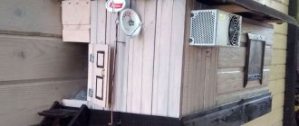
Another homemade product for those who are bored at home
I needed a couple of antennas for digital, in places with “not the best reception”... I went shopping (this was before self-isolation - if it’s relatively budget-friendly, then it’s complete G. The more expensive one looks decent, but how it works is questionable.
I decided to make something homemade. It was somehow awkward to “twist” an antenna from a piece of cable (although rumor has it it works) - I wanted something simple, but more decent and advanced
In fact, the one I made is not radically more complicated, but somehow more “solid” or something. And the results of its testing were very encouraging, so I decided to sketch out a short description of what and how, in case someone else finds it useful 
... even if my street cats have a “normal” antenna on their house, what can you do without an antenna?!
The wire is not all finished yet, now we’ll assemble something!
In the places described, I previously used home-made broadband log-periodic antennas, probably since the “beginning of perestroika.” They worked well in analog and not only on UHF, but “for some reason, digital was too tough for them.” I didn’t really delve into the essence of the reasons, I removed them and began to think about what to replace them with. Here is one of them, waiting for a place in the trash
A little history
In the early 60s of the last century, our compatriot Kharchenko K.P. developed a simple flat zigzag antenna with good characteristics.
Copyright certificate No. 138277 for an invention called “Band directional antenna” was issued to Konstantin Pavlovich Kharchenko in 1961 (according to his application dated June 16, 1960). In the same year, materials were published in the magazine “Radio” for repetition by radio amateurs.
The antenna is not critical to materials and dimensions during manufacturing, has a simple good match with the reduction cable, and it successfully combines multiple elements of a common-mode antenna array with a single feed point.
From coaxial cable
You can actually make a TV antenna manually using a cable:
- Cut approximately 530 millimeters of cable.
- Strip the cable on both sides, fastening the braid into a bundle and exposing the central core.
- Twist the cable into a ring or diamond shape and secure it with tape to the plywood. The distance between the cable rings should be 2 centimeters.
- Cut a piece of coaxial cable - 175 centimeters. Make a horseshoe-shaped matching device out of it. To do this, you need to strip the wire from both ends, as you did in the process of making rings.
- Prepare the antenna cable. The plug is put on one side, and the other is stripped. It is necessary to remove the central core and braid.
- Align the ring and matching device with the antenna cable.
As a base, you can use not only plywood, but also plexiglass.
Theory and calculations
The described antenna, in theory, has a horizontal “figure-of-eight” radiation pattern and a relatively high gain, which can be further increased by using a reflector/reflector.
To obtain maximum gain on all channels, it is necessary to make an antenna approximately in the middle of the range between the multiplexes used.
Finding (for calculations) the frequencies of multiplexes used in your region is easy,
for example, a request like “dvb-t2 channel frequencies” + “Krasnodar”
I found something like this:
The middle, between “my” two multiplexes, is 700 MHz - we will calculate the antenna at this frequency.
As a basis for calculating the dimensions of the antenna, we take the drawing of its author
Calculate the wavelength: λ = 300 / f [m]
300/700 = 0.428m, approximately 43cm length of each side of the rhombus
λ/4
=43/4= 10.75
The total length of the material we need (11cm*8=88cm) is less than a meter. The distance between the reduction contacts, where we will solder the cable, is 10-12mm (the standard value for this antenna for frequencies below 900 MHz).
I will make a simple antenna, without a reflector, however, to further increase the gain of this antenna, it is quite possible to install it behind it
for example, from a metal mesh/grill, foil material or simply a metal plate. Its dimensions should be approximately 20 percent larger than the dimensions of the antenna and it should be located at a distance of ƛmax/7. For my case: wavelength (channel 39) 300/618, it turns out...49/7= that is, about 7cm
For those who are too lazy to do the calculations themselves
— you can use an online calculator, the results will differ only slightly from those I received. Here, for example, this one - here you immediately enter the frequencies of two multiplexes and get the dimensions of the antenna (without a reflector) Or another option, with a reflector - I really want to note that in the second option a slightly different calculation option is used, different from the author’s. An antenna with angles other than 90° is assumed and the reflector distance is calculated as λ/8
To make the antenna sheet, it is recommended to use aluminum or copper (copper is easily soldered) with a diameter of 3 mm and higher - the larger the diameter, the more broadband the antenna is. You can use tubes; the thickness of the walls is not important, since only the surface of the material is used (in fact, you can wrap any dielectric with foil to obtain the required material). However, in my opinion, the easiest way is to buy a meter of large-gauge copper wire at an electrical supply store.
How to choose the right tuner for digital TV
Watch your favorite movies and TV series on any device thanks to More TV for only 299 rubles per month. Don't miss out on your 7 days FREE subscription! Subscribe
A TV tuner for a TV must be selected based on several rules:
Useful: Which set-top box to buy for digital television
World Vision or BBK is considered one of the most reliable and at the same time budget brands. Manufacturers of these devices always focus on the latest digital TVs and multimedia updates. They take into account the wishes of customers, creating a better and more convenient device.
Antenna assembly
Let's remove the insulation from a piece of wire one meter long.
I got a wire with a diameter of 4.5mm
The tools you will need are a vice and a hammer. Measure approximately 11cm each and bend at an angle of 90°
The end result is to get such a “geometric” figure
We cut off the excess and solder the ends. It should look something like this...
Solder the cable as shown in the photo.
We lay the cable along one side of the square and secure it with clamps. This arrangement of the cable is necessary for its coordination (there are different opinions, not everyone agrees with this statement).
When using a reflector, the antenna sheet at the extreme points of the squares can also be secured using metal stands, for example, soldered onto the remains of the same copper wire - there are points with zero potential (highlighted in green). In other places, fastening is allowed only through a dielectric.
What is a built-in TV tuner?
After studying the characteristics of the equipment, the following question may arise: what is a built-in TV tuner for a TV. This is a TV tuner for a TV that is factory installed. This model has advantages, since during operation you will not need to connect the TV separately to the Internet. You can also avoid lengthy setup of functionality, which usually happens when using an external tuner. In addition, the built-in TV allows you to select broadcast standards.
Useful: Which TVs do not require a set-top box
Tests
And finally, a performance check and a rough
assessment of the quality of the resulting antenna.
In fact, everything is simple with the test - turn it on, it works! And to evaluate whether the game was “worth the candle,” let’s compare the parameters of the received signal from the manufactured antenna with the one I’m already using at the dacha, with a declared gain of 11dBi
The antenna is installed in the attic of a country house, at a distance of approximately 16 km from the tower.
Signal level: factory stationary antenna on the left / homemade on the right
At first glance, the difference is only 1% (95 versus 94) - but this is not a completely correct comparison, since my external antenna is connected through a splitter, which further weakens the signal.
Vibrator connection
Considering the fact that the frame is symmetrical, and the connection is made to an asymmetrical antenna cable, you need to use a matching device. The best option is a short-circuited loop. It is made from pieces of coaxial cable. The left segment is a feeder, and the right one is usually called a train. In the place where the feeder and cable will be connected, we fix the cable, which is subsequently connected to the TV.
What should be the length of these segments? The calculation is carried out in accordance with the wavelength of the received TV signal.
At one end you need to cut the cable, removing the aluminum screen. The braid must be twisted into a tight rope. We cut off the central conductor down to the insulation. The feeder also needs to be cut. Remove the screen, made of aluminum, and then twist the braid. However, we leave the central conductor.
The further assembly process is carried out as follows:
- Solder the cable braid and feeder conductor to the left edge of the vibrator.
- The feeder braid needs to be soldered to the right edge of the vibrator.
- A metal jumper connects the cable braid to the lower end of the feeder. These elements can also be fastened with metal wire. The main thing is that there is proper contact with the braid.
- The braid determines not only the electrical connection, but also the distance between the sections of the matching device.
- If there is no metal wire and jumper, then twist the braided lower part of the cable into a bundle, after first removing the screen and removing the insulation. To ensure proper contact, you need to solder the wire harnesses using solder that melts easily.
- The cable pieces should be parallel to each other. Distance – 50 millimeters (small error is acceptable). To secure the distance, special clamps made of electrical insulating materials are used. You can also attach the matching device to the textolite plate.
- The cable that is inserted into the TV socket should be soldered to the feeder (to the bottom). The braids are interconnected, like the central conductors.
To reduce the number of connecting elements, the feeder and cable connected to the TV can be made one. Remove the insulation where the feeder ends. This is done in order to install the jumper.
A matching device is a mandatory element that helps prevent interference. It will be especially useful if the signal transmitter (TV tower) is located at a great distance.
Assessing the performance of the antenna
Let's try to make a more correct comparison by connecting through the splitter input.
Well, in addition, for clarity, let’s add the number of participants List of antennas taking part in the comparison:
1. External antenna Funke BM 4551 external long-range,
declared gain, from some sources (bought at Yulmart), up to 16dB
2. There is an old UHF loop antenna, from TV Electronica 313d, I must say, despite its simplicity, it’s a very good antenna, that’s why it’s been preserved
3. I went to the store and bought for comparison in the review one of the cheapest, such as a symmetrical vibrator (100% the most purchased by pensioners, due to the low price).
I will carry out all “measurements” at one point, located as close as possible to the external antenna - its location was experimentally selected based on the maximum signal, so we can say that the conditions are approximately the same
So, we have already seen the signal level from the external antenna at 95% (at the time of current measurements it showed 94%), we take it as a standard. All comparisons are made by connecting antennas to the input on the splitter, to which an external antenna is usually connected.
Loop antenna, from Electronics 82% on 39 multiplex and 66% on 60
Budget with “horns” - 62%/38% (on the verge of losing the broadcast)
Double square - 92% on both multiplexes, about a couple of percent less than the external one
Out of curiosity, I decided to check the work of the reflector, which is easy to make from any metal mesh, plate or even foil... It REALLY works noticeably! The level rose to 96%!, which is even higher than the stationary one, with a declared gain of 11dB.
The most interesting thing is the object that I used as a reflector!
There was no foil in the house; the only thing available with a metal surface of the required size was... a laptop cover (I have a metal case). But the main thing is the result! It’s clear that I’m not going to “tie” the laptop to the antenna, and its amplification is enough for me without a reflector
Miniature set-top box with micro-USB OTG
If you are a radio amateur, then on the radio market you can purchase all the components for a homemade digital receiver. Such a homemade product may turn out to be several times cheaper than its certified counterpart. But you'll have to work on it.
Main components
In general, if everything is done correctly, the set-top box will work on mobile gadgets, TV and PC. As an example, you can assemble a DVB-T2 set-top box like a small stick. Main technical characteristics:
You can create an exact copy of the Geniatech PT360 whistle. The differences will only be visible on the body. Since the manufacturer will not be indicated there. This small gadget can work with a smartphone, tablet, Android TV-box, and even a Windows-based PC.
It is important to understand that soldering all elements of the console requires certain skills, knowledge and equipment. But you can do it easier and purchase a Chinese copy of the original DVB-T2 set-top box on the radio market or AliExpress, modify it to an adequate level and use it everywhere.
Reconfiguration
To create a copy of the Geniatech PT360 set-top box for digital television with your own hands, you need to open it in order to finalize it. It is recommended to modify the whistle if it gets very hot. Otherwise, you don’t have to go into its insides.
To open it, you need to carefully remove one half of the case. It should be taken into account that the body is fastened quite tightly.
Inside the case there is:
Datasheets indicate that the receiver supports terrestrial digital DVB-T/T2, cable digital DVB-C/C2 and analog. As for the heat sink, it is constructed as follows: “heat leaves the microcircuit through a through heat sink on the board (indicated by a red arrow) and along the copper substrate into the antenna braid.” In fact, the role of a radiator is played by a banal copper braid. With this approach, after a long period of operation, the heating reaches such a limit that you can simply burn your finger by touching the antenna output.
To prevent this baby from floating along with the microcircuit elements in a closed case in the summer, you can build a small radiator. Any 2.5 mm aluminum sheet is suitable for riveting it. For example, you can cut a primitive radiator from a profile. Then, using copper foil and hot glue, bring the foil layer out. In this way, heat is transferred to part of the board on the opposite side.
You can glue such a heatsink onto a memory chip using superglue and thermal paste:
Do everything as carefully as possible, since you only try once and it will be impossible to clean the glue that has been dropped in the wrong place.
For greater efficiency, glue the plate and copper foil together and bring it out.
Assembly and testing
After installing the homemade heat sink plate, close the housing cover and connect the antenna to the antenna input. You can also check operation with a whip antenna. And the experimental device will be a smartphone with OTG support and Android version no lower than 4.1. The same conditions apply to other gadgets.
Since the connected receiver will receive power from the device, the energy consumption will be equal to 1000 mAh battery for 3-4 hours of operation.
The gadget works with the PadTV HD application, but can also work with other programs for watching a television channel.
If the signal level is high-quality, then the found channel will remain in memory.
Using a microUSB - USB adapter, the TV tuner works perfectly under Windows. The OS can detect the drivers on its own.
Watch your favorite movies and TV series on any device thanks to More TV for only 299 rubles per month. Don't miss out on your 7 days FREE subscription!
Conclusion:
I can confidently recommend repeating it!
Simple, “cheap and tasty”... One of the simplest, indoor antenna mounts... with ordinary suction cups - if you’re lucky with the direction to the television center
The next antenna "recommended for repetition" is... log periodic
“Crazy hands” were with you. Good luck and good mood to everyone! ☕