Another homemade product for those who are bored at home
I needed a couple of antennas for digital, in places with “not the best reception”... I went shopping (this was before self-isolation - if it’s relatively budget-friendly, then it’s complete G. The more expensive one looks decent, but how it works is questionable.
I decided to make something homemade. It was somehow awkward to “twist” an antenna from a piece of cable (although rumor has it it works) - I wanted something simple, but more decent and advanced
In fact, the one I made is not radically more complicated, but somehow more “solid” or something. And the results of its testing were very encouraging, so I decided to sketch out a short description of what and how, in case someone else finds it useful 
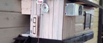
... even if my street cats have a “normal” antenna on their house, what can you do without an antenna?!
The wire is not all finished yet, now we’ll assemble something!
In the places described, I previously used home-made broadband log-periodic antennas, probably since the “beginning of perestroika.” They worked well in analog and not only on UHF, but “for some reason, digital was too tough for them.” I didn’t really delve into the essence of the reasons, I removed them and began to think about what to replace them with. Here is one of them, waiting for a place in the trash
A little history
In the early 60s of the last century, our compatriot Kharchenko K.P. developed a simple flat zigzag antenna with good characteristics.
Copyright certificate No. 138277 for an invention called “Band directional antenna” was issued to Konstantin Pavlovich Kharchenko in 1961 (according to his application dated June 16, 1960). In the same year, materials were published in the magazine “Radio” for repetition by radio amateurs.
The antenna is not critical to materials and dimensions during manufacturing, has a simple good match with the reduction cable, and it successfully combines multiple elements of a common-mode antenna array with a single feed point.
Superposition of waves (superposition principle)
Waves transfer energy from one place to another.
Left untouched for a long period of time, the surface of the pool water will appear flat and still. If you disturb water in one place, water molecules will disturb neighboring water molecules, which will disturb neighboring water molecules, and so on, until the disturbance reaches the edge of the pool.
The molecules that started the chain of events remain in place close to their initial location, but the disturbance will reach the edge of the pool in seconds. Waves transfer energy without transferring matter.
Single wave in the pool
Waves, as we describe them, are the movement of disturbances through a medium. A single initial disturbance or a million such disturbances lead to the propagation of the disturbance by a chain reaction of collisions of molecules in the pool.
Graph of the propagation of two waves in a pool
When two waves disturb the same region of space, their amplitudes will add or subtract, creating either constructive or destructive interference. This practice of temporary addition or subtraction is called the principle of superposition.
Constructive wave interference graph
Once the waves interfere at a particular location, they continue to move in the same direction and at the same speed at which they started for as long as they remain in the same medium. The speed and direction may change as the wave enters a new medium. Sound waves travel through air, water waves travel through liquids—the substances through which the waves travel are called “medium.”
Electromagnetic waves can travel through media such as air and water, or through the void of space - they do not require a medium to propagate energy from one place to another.
Theory and calculations
The described antenna, in theory, has a horizontal “figure-of-eight” radiation pattern and a relatively high gain, which can be further increased by using a reflector/reflector.
To obtain maximum gain on all channels, it is necessary to make an antenna approximately in the middle of the range between the multiplexes used.
Finding (for calculations) the frequencies of multiplexes used in your region is easy,
for example, a request like “dvb-t2 channel frequencies” + “Krasnodar”
I found something like this:
The middle, between “my” two multiplexes, is 700 MHz - we will calculate the antenna at this frequency.
As a basis for calculating the dimensions of the antenna, we take the drawing of its author
Calculate the wavelength: λ = 300 / f [m]
300/700 = 0.428m, approximately 43cm length of each side of the rhombus
λ/4
=43/4= 10.75
The total length of the material we need (11cm*8=88cm) is less than a meter. The distance between the reduction contacts, where we will solder the cable, is 10-12mm (the standard value for this antenna for frequencies below 900 MHz).
I will make a simple antenna, without a reflector, however, to further increase the gain of this antenna, it is quite possible to install it behind it
for example, from a metal mesh/grill, foil material or simply a metal plate. Its dimensions should be approximately 20 percent larger than the dimensions of the antenna and it should be located at a distance of ƛmax/7. For my case: wavelength (channel 39) 300/618, it turns out...49/7= that is, about 7cm
For those who are too lazy to do the calculations themselves
— you can use an online calculator, the results will differ only slightly from those I received. Here, for example, this one - here you immediately enter the frequencies of two multiplexes and get the dimensions of the antenna (without a reflector) Or another option, with a reflector - I really want to note that in the second option a slightly different calculation option is used, different from the author’s. An antenna with angles other than 90° is assumed and the reflector distance is calculated as λ/8
To make the antenna sheet, it is recommended to use aluminum or copper (copper is easily soldered) with a diameter of 3 mm and higher - the larger the diameter, the more broadband the antenna is. You can use tubes; the thickness of the walls is not important, since only the surface of the material is used (in fact, you can wrap any dielectric with foil to obtain the required material). However, in my opinion, the easiest way is to buy a meter of large-gauge copper wire at an electrical supply store.
Antenna assembly
Let's remove the insulation from a piece of wire one meter long.
I got a wire with a diameter of 4.5mm
The tools you will need are a vice and a hammer. Measure approximately 11cm each and bend at an angle of 90°
The end result is to get such a “geometric” figure
We cut off the excess and solder the ends. It should look something like this...
Solder the cable as shown in the photo.
We lay the cable along one side of the square and secure it with clamps. This arrangement of the cable is necessary for its coordination (there are different opinions, not everyone agrees with this statement).
When using a reflector, the antenna sheet at the extreme points of the squares can also be secured using metal stands, for example, soldered onto the remains of the same copper wire - there are points with zero potential (highlighted in green). In other places, fastening is allowed only through a dielectric.
Equipment required for connection
All work in the apartment occurs after the provider has organized a central cable connection . This means that a wire has been installed in the subscriber’s home, from which the construction of the entire signal transmission network begins. However, it is worth remembering that broadcasts in digital format are not capable of processing older TVs. The user may encounter a number of situations.
- Old TV. In this case, you will need a set-top box on which you can set up digital cable television.
- New modern TV. If it has a digital tuner, you don't have to buy a separate set-top box.
Finally, there is an option where the provider offers encrypted digital content. This situation directly implies the purchase of additional equipment. This could be a CI interface module for digital television or a set-top box with an authorization system using a smart card.
Important! Another feature of digital broadcasting is considered unpleasant by a huge number of consumers. To connect cable TV in encrypted format, you will need to buy equipment for all TVs. And for each set-top box or interface module you need to pay a subscription fee.
Users who have an old TV receiver find themselves in a similar situation. However, today providers are trying to offer subscribers the opportunity to immediately watch content on several TVs or other gadgets. This is “Multiscreen”, which allows you to save on watching channels from a second and even third gadget.
Tests
And finally, a performance check and a rough
assessment of the quality of the resulting antenna.
In fact, everything is simple with the test - turn it on, it works! And to evaluate whether the game was “worth the candle,” let’s compare the parameters of the received signal from the manufactured antenna with the one I’m already using at the dacha, with a declared gain of 11dBi
The antenna is installed in the attic of a country house, at a distance of approximately 16 km from the tower.
Signal level: factory stationary antenna on the left / homemade on the right
At first glance, the difference is only 1% (95 versus 94) - but this is not a completely correct comparison, since my external antenna is connected through a splitter, which further weakens the signal.
Assessing the performance of the antenna
Let's try to make a more correct comparison by connecting through the splitter input.
Well, in addition, for clarity, let’s add the number of participants List of antennas taking part in the comparison:
1. External antenna Funke BM 4551 external long-range,
declared gain, from some sources (bought at Yulmart), up to 16dB
2. There is an old UHF loop antenna, from TV Electronica 313d, I must say, despite its simplicity, it’s a very good antenna, that’s why it’s been preserved
3. I went to the store and bought for comparison in the review one of the cheapest, such as a symmetrical vibrator (100% the most purchased by pensioners, due to the low price).
I will carry out all “measurements” at one point, located as close as possible to the external antenna - its location was experimentally selected based on the maximum signal, so we can say that the conditions are approximately the same
So, we have already seen the signal level from the external antenna at 95% (at the time of current measurements it showed 94%), we take it as a standard. All comparisons are made by connecting antennas to the input on the splitter, to which an external antenna is usually connected.
Loop antenna, from Electronics 82% on 39 multiplex and 66% on 60
Budget with “horns” - 62%/38% (on the verge of losing the broadcast)
Double square - 92% on both multiplexes, about a couple of percent less than the external one
Out of curiosity, I decided to check the work of the reflector, which is easy to make from any metal mesh, plate or even foil... It REALLY works noticeably! The level rose to 96%!, which is even higher than the stationary one, with a declared gain of 11dB.
The most interesting thing is the object that I used as a reflector!
There was no foil in the house; the only thing available with a metal surface of the required size was... a laptop cover (I have a metal case). But the main thing is the result! It’s clear that I’m not going to “tie” the laptop to the antenna, and its amplification is enough for me without a reflector
What are the advantages of digital cable television
Important!
To watch digital TV on a TV, the subscriber must enter into an agreement with the provider. It is he who forms the list of available channels and other content. You won’t be able to connect cable TV for free and completely on your own. The digital broadcast format works as follows:
- a narrow frequency band with a central carrier is used to broadcast channels;
- information is transmitted in packets in digital format, in DVB-C encoding;
- The data includes not only information about the picture, you can add a TV program guide, subtitles, multiple audio tracks and much more to the stream.
Deciding to install cable TV in an apartment is very easy if you know about its advantages. The main set is in digital broadcast format. This means that interference has very little effect on image quality. Data is transmitted in redundant packets. Decoding equipment in an apartment, even with severe losses, is capable of constructing a high-quality image.
The second main advantage of digital is the presence of service information in the stream. These are subtitles for people who are hard of hearing, additional audio tracks for foreigners or those who want to listen to alternative accounts of events. Finally, a TV guide system and a detailed TV program guide will ensure you don't miss your favorite show or movie.
And the finishing touch is the ability to choose the optimal set of channels for yourself. The provider parameters allow you to create a set of broadcast packages for the user. Or make only some channels from a certain list available. Usually a free or inexpensive package of several programs is offered. Other channels are formed into separate offers; the user can choose and pay only those that are interesting to him.
Conclusion:
I can confidently recommend repeating it!
Simple, “cheap and tasty”... One of the simplest, indoor antenna mounts... with ordinary suction cups - if you’re lucky with the direction to the television center
The next antenna "recommended for repetition" is... log periodic
“Crazy hands” were with you. Good luck and good mood to everyone! ☕
Wave reflection
When waves pass from one medium to another, part of their energy is transferred, part of the energy is reflected, and part of the energy is dissipated into the environment.
The material properties of these two media determine the ratios of transmission to reflection and scattering. And also the properties of materials determine whether the wave will be inverted when reflected.
Transmission and reflection of single wave pulse energy
A continuous incident wave (orange) hits the interface, where some of the energy is reflected (light orange) and some of the energy is transmitted (dark orange)