The reliable operation of any television device is largely determined by the quality of the devices used, which provide not only reception, but also amplification of terrestrial meter and UHF signals. Recent advances in the field of TV information processing have made it possible to develop special methods for calculating the designs of receiving antennas, which can have a wide variety of designs.
Television antenna designs
Any such antenna is usually characterized by a number of indicators, sometimes distinguished by their inconsistency and complexity of coordination. In subsequent sections, special attention will be paid to ways to overcome these contradictions.
Indoor active receivers Delta
The main advantages of Delta antennas are their affordable cost, ease of use and good quality. The production of these receiving devices was launched about 18 years ago in St. Petersburg, since then the product has been constantly improved, its technical capabilities and range of functions have expanded. The manufacturer offers users a wide range of models, ranging from indoor digital antennas to outdoor active devices for individual and collective action.
Among indoor devices, Delta K131 is popular. Compared to its predecessors, its receiving characteristics have improved, but the cost remains the same. The broadband product has compact dimensions and is completely collapsible. It belongs to the category of active models, since it is equipped with a fairly powerful amplifier, and receives power from a special unit connected to the network.
Among the line of indoor appliances, it is worth highlighting one more model - Delta K331. The broadband device is small in size, can be easily and quickly assembled and disassembled, and a powerful amplifier and power module are included as standard. Recently, the model range was replenished with products K331A-02 and K331A-03. They are less convenient to transport, but have a more stylish design.
Outdoor structures can be divided into two main categories - with and without cable. The second type includes models marked “b/k”. The most common type is the outdoor antenna H311A-01. It is perfect for use in a suburban or summer cottage.
Video
The Delta antenna is in great demand among many TV viewers. First of all, it is chosen for its affordable price, high quality and ease of use. Their production was first launched 17 years ago at a plant operating in the city of St. Petersburg. Over the years, the products have been constantly improved, new functions and capabilities have been added.
During this time, television antennas have proven themselves to be reliable and efficient equipment, the use of which ensures enjoyable viewing of your favorite films and TV shows. Thanks to this, the products are in great demand and are being chosen by an increasing number of television viewers.
High quality material
High-strength steel is used to produce Delta outdoor antennas. Special powder paint is used as a coating. The use of steel by the manufacturer made it possible to set an acceptable price for the products.
The manufacturer offers a wide range of models:
- Indoor television;
- External individual;
- Outdoor models of collective reception;
- Devices for other purposes - for cellular communications, VHF antennas, etc.
Indoor models
The first models began to be produced back in the days of the Soviet Union. This antenna is the only one that does not have a distinctive alphanumeric index. During the formation of the antenna market, it quickly gained great popularity due to its compactness and ease of transportation. However, antennas also had negative sides.
The antennas were completely collapsible and easily broke when dropped. In order to fix this, the developers introduced a new model - Delta K131. K determines that the antenna is indoor. The cost of the new model remained the same, but the quality has become higher. Partial legibility ensured the product's durability and higher drop resistance.
Broadband indoor antennas
The very first model is Delta K331, which became popular in the shortest possible time. The antenna is completely collapsible and very compact; it has a modification supplemented by a powerful power supply and amplifier. The range of manufactured all-wave indoor antennas has been expanded with newer models - K331A02, K331A03, which are less convenient to transport. Modern design, beautiful packaging and good quality have provided them with a high level of popularity.
Outdoor TV antennas
The manufacturer provides for the production of external antennas in two versions: cable and models without cable.
Models of the first type are designated by the corresponding prefix “b/k”. Depending on the model range, the cable length is set differently by the manufacturer. The Delta N311-01 antenna was the first in this model range; it appeared on the market more than 15 years ago, and currently the antenna remains one of the best-selling among the models of the Delta family. The model is time-tested and has proven itself as a reliable and inexpensive antenna.
H311-01 is widespread, in great demand, and is available in two versions:
- N311A-01 is the best option for use outside the city, complemented by amplification in the MV and UHF range;
- H31A1 is an excellent example for urban conditions. Due to the similarity of the letter designations, the two different models are often confused.
The wide range of Delta antennas presented by the manufacturer will allow everyone to choose the best option.
Device types
Products of the “Wave Channel” type have become widespread among consumers. Their main differences are high gain and narrow radiation pattern. The second category is log-periodic antennas, which have a similar design, but a completely different operating principle.
The manufacturer has proposed a universal Delta antenna, the use of which ensures high signal quality. The existing differences between indoor and outdoor options are determined by the number of working elements and overall dimensions. Using an outdoor model will provide better reception than an indoor one. The advantage of the internal one is its compact size. Despite this, using the device in close proximity to the transmitting center will allow you to achieve high signal quality.
Design
Delta products are a combination of a half-wave field that provides reception of dead-range channels, a wave channel and a log-periodic antenna that provides reception of high-frequency decimeter waves. Coordination of both parts reduces mutual influence on each other and improves the level of reception quality.
Characteristics of outdoor models
- Frequency indicators – MV, UHF;
- 3-14 dB – gain parameter;
- The protective effect of the devices is 12 dB;
- Cable resistance parameters 75 Ohm.
Installation features
The Delta antenna connects to the TV in the same way as products from other manufacturers. You will need to connect a simple plug to the prepared end of the cable. It is important to ensure that the connection does not lead to a bridge between the central core and the screen. The cable connection should be made in accordance with the instructions specified by the manufacturer.
The accompanying documentation provides a connection diagram. It is necessary to pay attention to sealing the input when connecting. Moisture that gets into the amplifier will very quickly damage it. The capillary effect of the cable will cause the cable to suck in water. Subsequently, it will be practically impossible to dry it, and due to corrosion of the shielding braid, the cable will soon become unusable.
Failure to follow the rules during installation and operation of Delta antennas will result in low signal quality and rapid failure of the equipment. Delta products are very popular, which is ensured by their high quality and affordable cost.
Video
Delta N311-01A antenna design
Delta N311-01A is a version of the Delta 311-01 antenna without an amplifier. An all-wave television antenna with a broadband amplifier is used in conditions of unsatisfactory reception in the VHF and UHF ranges. Receives signals from analogue and digital television broadcasting in the frequency range 48.5-890 MHz and consists of a decimeter antenna and a meter range vibrator. The antenna has uniform gain over the entire frequency range.
How to set up and connect the Delta antenna
In some cases, only outdoor products equipped with an active module can provide high-quality reception. An indoor design is suitable if the distance to the nearest TV tower does not exceed 10-15 km. Among the range of Delta outdoor receivers, the H311A-01 model occupies a special place. The broadband active antenna is equipped with a power supply with a built-in separator. It picks up the signal well when the distance from the repeater does not exceed 40 km.
The gain for UHF channels is 20 dB. A distinctive design feature is the combination of two devices: a vibrator and a speech therapy receiver. Each component is made of high quality steel, and a layer of special paint provides additional protection.
The fastening components are also coated with a special composition: galvanization protects against corrosion and adverse weather conditions. When assembled, the product has a length of 83 cm, and its weight reaches 1.6 kg. The advantages of the Delta H311A-01 receiver include the following:
- suitable for receiving signals in DVB-T2 format;
- The package includes an amplifier that increases the signal level and controls the attenuation in the cable;
- operating temperature range varies from -40 to +50 degrees;
- It is supplied unassembled, but the kit includes the necessary fasteners.
How to Improve Video Quality Using Artificial Intelligence
Installation and connection of external receiving structures from various manufacturers is practically no different. The Delta H311-01 antenna is connected as follows:
- The first step is to assemble the device. It is recommended to use the manufacturer's instructions, which should be included in the standard kit.
- The next step is connecting the cable. There are two connection methods available here: using a clamp or using a special connector, but in the case of Delta, the first option is used. You will need to remove the top layer of insulation from the wire, remove the foil, and twist the braid into a flagellum. The central core is crimped with a clamp, and those who know how to use a soldering iron can solder the braid and core to the clamp contacts.
- A power module will need to be connected to the device. First, it is recommended to check the functionality of this component. After plugging into the outlet, the indicator light should light up.
The outdoor antenna will need to be mounted on a special mast or wall bracket
It is not recommended to bypass the special grounding clamp. If the device is mounted on a wooden pole, any wire will do for grounding
A metal pin driven into the ground to a depth of about 60-80 cm will protect the device from thunderstorms and electromagnetic pulses.
At the initial stage of connection, it is not recommended to firmly fix the product. Additional adjustments may be required or a more precise direction in relation to the tower may be required. If the signal level is excellent and all available channels are displayed on the TV screen, then you should firmly fix the device.
Specifications
| Ranges | MV, DMV |
| Gain | 20/20/20 dB |
| Protection factor | 0/0/12dB |
| Length | 830 mm |
| Weight | 1.6 kg |
| Material | steel |
| Antenna type | active |
| Amplifier power | 12 V |
The design of the antenna is quite simple and therefore it is quite accessible for repetition. The main elements that make up the antenna are: decimeter part; vibrator MV; matching board and signal amplifier. Complex elements include: a matching board and an amplifier, but you can do without them by installing an SWA type amplifier.
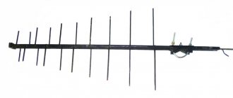
The decimeter part is a log-periodic antenna with 20 vibrators.
A log-periodic antenna (LPA) consists of two pipes located one above the other, to which the vibrator arms are attached alternately.
The cable is connected to the LPA without a special matching device as follows. A cable with a characteristic impedance of 75 Ohms is inserted into the down tube at one end and exits at the other. The cable braid is soldered to the end of the lower pipe, and the central core is soldered to the end of the upper pipe.
Depending on the wavelength of the received signal, several vibrators are excited in the antenna structure, the dimensions of which are closest to half the wavelength of the signal. At a given signal wavelength, only one trio of vibrators is excited, while the rest are detuned and do not affect the operation of the antenna. The antenna gain drops somewhat, but the bandwidth is much wider.
It is useful to know that the smoother the surface of the conductors from which the antenna is made, the higher its quality indicators (higher the quality factor).
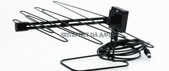
The MV antenna is designed extremely simply - it consists of two vibrators 110 cm long, attached to the protective housing of the amplifier.
The matching board and amplifier are hidden in a sealed housing.
The balancing device is used to match meter and decimeter range antennas with an amplifier.
How to work with Delta - attention to detail
To get the most out of this valuable tool, Delta indicators should not be neglected during technical analysis. In this case, you can use the Footprint chart, the Delta indicator on each bar, and the cumulative Delta, which displays the total Delta for a period of time, for example, for a trading session. Sometimes it is the Delta indicators that can give a trader the optimal point to enter the market. For example, by the length of the negative Delta, you can determine the end of the accumulation period and enter a trade right before the start of a major uptrend.
To learn how to work with Delta correctly and profitably for your trading, you can take a course at the Alexander Purnov School of Trading under the guidance of an experienced mentor. In addition, after subscribing to our blog, valuable materials on trading and finance will be available.
Antenna connection
The photo shows an option when the amplifier is installed correctly, and an option when it is incorrect
Wrong Correct
The amplifier has contact pads to which the antenna waveguides are connected. If the amplifier is installed incorrectly, its input remains unconnected; naturally, the signal from the antenna does not reach the amplifier input, and the antenna does not work . You can spend time installing the antenna, but the result will be negative, you will have to redo the work, and you may need to replace the amplifier, since very often, if connected incorrectly, SWA amplifiers fail. We will assume that the antenna assembly has been completed and everything has been done correctly.
Indoor active structures
- Delta H311 device. The design combines several types of antennas: an MV vibrator and a UHF wave director. The second component is necessary just for receiving broadcasts in the DVB-T format. Suitable for use in places with poor signal reception, at a short distance from the television tower. The advantage of the design is that it is not equipped with active modules, and therefore does not require connection to the mains. It is not afraid of voltage surges, and due to the absence of amplifiers, the service life increases. To increase the reception rate, you can purchase an active module.
- Region 67
- Indoor active antenna Delta Digital K131A.03 12V. Used to receive broadcasts in DVB-T format The device can be used in areas with poor coverage. It has the ability to adjust the gain, and it is also possible to change the position angle up to 25 degrees.
Among external structures, the Delta H118A.F-5V model is popular. The device is equipped with a broadband amplifier that can improve reception quality and compensate for attenuation on any section of the cable. The amplifier receives power from a DVB-T2 set-top box or a TV equipped with a decoder for digital broadcasting. Suitable for installation in areas with any climate, operates at temperatures from -40 to +50 degrees. Among the advantages of the device, it is worth noting its low weight and size, high gain and collapsible design.
Antenna connection
The photo shows an option when the amplifier is installed correctly, and an option when it is incorrect
Wrong Correct
The amplifier has contact pads to which the antenna waveguides are connected. If the amplifier is installed incorrectly, its input remains unconnected; naturally, the signal from the antenna does not reach the amplifier input, and the antenna does not work . You can spend time installing the antenna, but the result will be negative, you will have to redo the work, and you may need to replace the amplifier, since very often, if connected incorrectly, SWA amplifiers fail. We will assume that the antenna assembly has been completed and everything has been done correctly.
TV antenna Delta
The Delta television antenna, produced by the Research and Production Association of Equipment and Communication Systems, has been in deserved demand among users in Russia and the CIS countries for many years. The product range includes devices in the meter range, decimeter range and broadband, amplifying signals in both ranges - VHF and UHF; collective antennas and individual use; outdoor and indoor, log-periodic and wave channel.
Model table
The table shows the characteristics of individual outdoor broadband television antennas Delta.
All of them are designed to receive TV channels 1 to 60 and are designed for viewing both analog and digital broadcasts. The letter A means that this is an active Delta antenna with an amplifier. Some models, for ease of connecting the antenna cable, are equipped with F-connectors and are designated by the letter F. Table: Delta television antennas
| Models | Peculiarities | Gain kit |
| H3311 | Symmetrical vibrator MV and log-periodic UHF | 0/1/9 |
| N3311A | Analog H3311 - with amplifier | 20/20/26 |
| N311.02 | Symmetrical vibrator MV and log-periodic UHF | 0/1/8 |
| H311.02F | Symmetrical vibrator MVI log-periodic UHF, F-connector | 0/1/8 |
| Н311A.02F | Analog H311.02F with amplifier | 20/20/26 |
| N311A.02 | Analogue N311.02 active | 20/20/26 |
| H1321 | Analog H321, aluminum | 1/1/4 |
| Н1321А | Analog H1321 with amplifier | 20/20/25 |
| H391 | Horizontal polarization | 1/6/8 |
| H391A | Similar to H391 - delta antenna with amplifier | 20/26/28 |
| N311A1 | A1- UHF amplifier | 0/1/20 |
| H341 | 0/1/11 | |
| H341A | Analog H341 active | 1/2/10 |
| H311-01 | 22 elements | 0/1/8 |
| N311A-01 | Analogue N311-01 with amplifier | 20/20/25 |
| H351 | 34 elements | 0/0/12 |
| H351A | Analog H351 active | 0/0/12 |
| H361 | 42 elements | 1/6/11 |
| H361A | Analog H361 with amplifier | 20/24/30 |
| H321 | 14 elements | 0/1/4 |
| H321A | Analog H321 active | 20/20/25 |
| N321A1 | Analog H321 with UHF amplifier | 0/1/16 |
| H375 | 43 elements | 3/6/11 |
Delta antenna with amplifier
Purpose - individual reception of television broadcast signals of horizontal polarization in the frequency range from 48.5 MHz to 790 MHz from television channels 1 to 60.
The Delta H311 antenna ensures viewing of television programs in an area of reliable reception, the active model H311A with a built-in amplifier is used in an area of a weak signal from a television center. The range and quality of reception depend on the installation location and height, the power of the television transmitter, the terrain and the level of electronic interference. The delta antenna with an amplifier is configured to receive television signals in accordance with the table of frequencies of television channels of terrestrial television, given in the section Terrestrial television channels."
Delta H311 antenna design
TV antenna Delta
H311 is an antenna module - a log-periodic design for decimeter waves and two vibrators for receiving meter waves. The device is mounted on a mast and is oriented towards the television center using a fastening unit. The antenna box contains a matching board, or antenna amplifier model H311A.
Assembly and installation procedure
Antenna Delta N 311-01 connection diagram. First of all, meter range vibrators are assembled and connected to the antenna box. Next you need to connect the antenna cable, for which you need to remove the protective sheath, shielding braid and internal insulator, freeing them by 10 mm. Make the connection: remove the cover of the antenna box, unscrew the nut securing it, insert the cut end of the cable into the central hole and connect it to the matching board. Install the H311 assembly on the mast and secure it at a height sufficient for direct visibility to the television tower. By rotating the device in one direction or another, use the best image to determine the optimal orientation angle and secure it completely. Fix the antenna cable on the mast, connect the grounding wire to the nut on the grounding stud located on the mounting unit.
Indoor antenna Delta
Delta indoor antennas are designed for receiving television signals indoors; their design and modifications are described in the section
"indoor antennas with amplifier."
Delta design and parameters
It is known that the delta antenna has the properties of several types of devices at once, since its design is a combination of a half-wave and log-periodic dipole. This feature makes it possible to implement in one product the possibility of all-wave signal reception from transmitting stations.
Antenna for router
These receivers take advantage of both types of designs; Moreover, the various parts of the structure are perfectly coordinated with one another. As a result of this combination, it is possible to obtain a universal antenna with minimal losses from the mutual influence of individual components and improved reception characteristics.
Important! At the same time, the developers managed to agree on the parameters of the supply cable, suitable for all existing frequency ranges.
An outdoor antenna of this class has the following main characteristics:
- Received frequencies cover the MV and UHF ranges;
- Effective gain (CA) - 3-14 dB;
- Attenuation coefficient (AC) in the lateral and rear directions - 12 dB;
- The characteristic impedance of the cable is 75 Ohms.
Additional Information. The KZN in this design refers only to the decimeter component of the entire antenna.
The spread in gain values indicates different gain levels for different parts of the frequency range, and dips mainly occur on meter channels. Since modern television broadcasting has a steady tendency to reduce them, there is no need to worry about this at all.
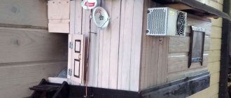
To increase the KZN in the UHF range, it is possible to modify the Delta antenna, which consists of equipping it with a special reflector, which is placed between the meter and decimeter parts. Those who have converted their antenna into a reflector know well that this element is made in the form of a special grating that attenuates the signals from the rear lobe, thereby increasing the overall gain (see photo below).
Delta with reflector
Note that all the parameters discussed above relate to passive types of antennas that do not have built-in television signal amplifiers or are designed as a separate module. As a result, the scope of application of such structures will be limited to areas that have direct visibility to the transmitting equipment.
Known types of antennas
Recently, the most common types of indoor UHF antennas are:
- The so-called “wave channel”;
- Log-periodic antenna;
- Half-wave vibrator of symmetrical type;
- A universal antenna called “Delta”, which provides reception of channels in the VHF and UHF ranges.
Let's look at each of these types of receiving devices in more detail.
Antennas of the “wave channel” type have a relatively narrow directivity lobe to the transmitting station, which is simultaneously combined with a high gain. These indicators are inextricably linked and directly depend on the number of links and the length of the antenna structure.
All these disadvantages can be overcome by using an antenna similar in design to a wave channel with a log-periodic arrangement of dipoles. Both of these varieties are capable of efficiently processing a signal only if the active elements are manufactured and placed with the utmost precision.
Another modification of simple-to-use household antennas for digital TV is a half-wave vibrator, which is an open quarter-wave line, the individual parts of which are located in one straight line (see figure).
Half-wave vibrator
This element is an integral part of most of the antenna equipment considered here.
Of particular interest are universal delta television antennas, designed specifically for receiving frequencies in almost the entire range of received waves (MV plus UHF). With some reservations, they can also be classified in the same class as those discussed earlier.
Some samples of these products are designed for installation within a room, and some of them can be installed outside the room on a balcony, for example (street design). The difference between these two designs is the different number of stacked elements (dipoles), as a result of which they are somewhat different in size and weight.
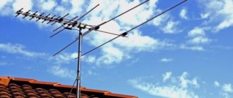
Naturally, an internal or indoor antenna does not have the same performance as an external one, however, it is quite suitable for receiving a signal from a not very distant television center (see photo of the external structure below).
Outdoor antenna "Delta"
Characteristics of household antennas
To evaluate the efficiency of receiving devices belonging to the “indoor antenna” category, the following indicators are introduced:
- Frequency range of the received signal;
- Directional pattern represented in the form of spatial lobes;
- Receiving device gain;
- Its dimensions.
The relationship between gain and directivity parameters to the source of the processed signal is the most difficult aspect when evaluating various antenna samples. As a rule, they appear as mutually exclusive conditions. Thus, as the amplification characteristics of a particular receiving device improve, its directional pattern narrows and vice versa.
On the one hand, such a limitation can be attributed to the advantages of antennas without an amplifier, since narrowing the direction of the received signal improves their noise immunity (does not allow extraneous and reflected radiation to pass through).
Important! On the other hand, antenna samples with a narrow directional characteristic will require extremely precise tuning to the television signal source.
Moreover, the slightest deviation from the given direction significantly worsens the quality of its reception (see picture below).
Directional pattern
The second most important parameter of household structures (the external delta antenna is also one of them) is the frequency range. Most of the known antennas of this class provide maximum gain in a fairly narrow frequency range, which can be expanded by partially reducing the gain.
Since modern television broadcasting is designed for a relatively wide frequency range, a universal indoor antenna must also meet these requirements. In addition, due to the difference in the characteristics of meter and UHF waves, the devices for their reception and processing differ significantly in their design, which especially affects the dimensions.
Modern digital television also uses the decimeter range for signal transmission, within which reliable reception is possible only with direct visibility to the transmitting station equipment. At the same time, at large distances from it, you have to either raise the antenna to a certain height, or take additional measures to increase its gain.
Connection procedure
To understand how to properly connect Delta to a television receiver, please note that this procedure is practically no different from connecting any other device of a similar purpose. In order to connect it correctly, you first need to cut the mating end of the cable wire for a contact connector or soldering
This operation is necessary in order to arrange it in the form of a standard plug connector, which will be used to connect to the input jack of the receiver
In order to connect it correctly, you first need to cut the mating end of the cable wire for a contact connector or soldering. This operation is necessary in order to arrange it in the form of a standard plug connector, which will be used to connect to the input jack of the receiver.
If a model with a built-in amplifier is used, its design must include another wire designed to connect the delta antenna to the power supply adapter (see the figure below).
Connection diagram
Important! When connecting a cable to a plug, under no circumstances should a short circuit be allowed between the screen braid and the thin central core. When carrying out the described procedures, it is recommended to follow the instructions for designing television connectors, which should contain a connection diagram
When carrying out the described procedures, it is recommended to follow the instructions for designing television connectors, which should contain a connection diagram.
Features of operation
Long-term operation of Delta type antennas in the open air requires careful sealing of the input and connection areas of the cable and wire. If there are no traces of treatment with protective agents on the product, you must perform this operation yourself (taking into account the capabilities of this model).
Moisture getting inside the amplifier circuit or on the contact connections can lead to failure of the entire structure, and the cable connected to it can become completely wet in conditions of high humidity. Possible consequences of these operational violations are a short circuit in the power circuits and complete burnout of the entire electronic part of the device.
Additional Information. The only correct way out of this situation is to completely replace the soaked cable along with the antenna plug.
Drying a wet cable product is unacceptable, since over time it will still fail due to the presence of internal elements damaged by corrosion (braided shielding, in particular).
In the event of a noticeable deterioration in the quality of reception on all or several television channels (or its complete loss), you should disassemble the plug and make sure that the wiring of the central core and braid are in good condition. If serious violations are detected, it is necessary to cut off the cable near the damaged connector and make a new contact connection in the form of an antenna plug.
In conclusion, we note that to independently assemble a Delta-type antenna, you need an appropriate level of training and skills to work with devices of this class. There is not enough professional data for this on the Internet, since all the information presented in the sections on this topic concerns mainly amateur radio samples.
Installation and configuration of active Delta antennas
To watch TV channels in digital format, you need special equipment, which, in addition to the receiver, includes a decimeter antenna. The method of installation and configuration of the structure will vary depending on its type and model range. City residents can use indoor devices, since most residential buildings are located a short distance from television towers. Outdoor equipment is used in regions with poor coverage, for example, in summer cottages or rural areas.
Installing a room receiver is not difficult. Each user is able to configure it without the help of specialists. You need to choose the right place. There should be no obstacles between the receiving device and the signal source. Subscribers who have a view of the TV tower from their window should not face any difficulties at all. Experts recommend not placing the product near other radio signal sources. If the apartment has a Wi-Fi router, the structure will need to be removed from it at a distance of several meters.
Installing a street structure is a more complex process that requires certain skills and knowledge. The first step is to take care of installing the mast and prepare the mounting location. Fastening is carried out vertically or horizontally, everything will depend on the structural features of the roof. The holder must be fixed as firmly as possible so that the structure does not blow off in strong winds. At the first stages of installation, you can not fasten it completely (leaving the opportunity to adjust the device and select the correct orientation). It is recommended to install an additional module for lightning removal. It consists of an lightning rod, a grounding conductor and a down conductor.
Antenna cable connection
When describing methods for connecting an antenna cable, I take examples of connecting antennas that are mass-produced. For various small-scale and homemade antennas, connections may be completely different.
There are mainly two connection methods used to connect the antenna cable.
2. Special F connector.
Let's consider both connections.
Clamped.
This type of connection is found on antennas where an SWA amplifier is used. The cable in “Delta” antennas manufactured in St. Petersburg and Rostov-on-Don is connected to the clamp. Therefore, let's consider this connection method using these antennas as an example. On antennas from other manufacturers, the clamp connection will be little different.
Clamp connection with spaced contacts.
This connection is typical for the Delta antenna.
To connect the cable, you need to remove the top layer of insulation from it.
Under the insulation is the cable braid and foil. The foil must be removed and the braid twisted into a flagellum. If the cable is of high quality and the braid is made of copper, tin the cable with tin solder to make it easier to crimp it with a contact clamp when connecting. The central core of the cable can be crimped with a contact clamp without modification. If you are “friendly” with a soldering iron, I advise you to additionally solder the cable braid and the central core to the contact clamps, this will be more reliable.
If the cable braid is made of steel, there is no need to tin it; for ease of connection, crimp it with a sleeve for a stranded electrical wire.
SWA type terminals .
Personally, I like this method of connecting the cable much more than the previous one. There is no need to worry about maintaining polarity; with this connection it is impossible to make a mistake. The cable is securely crimped with a fastening bracket, which gives additional strength to the mechanical connection of the cable to the antenna. The photo shows how to prepare the cable for connection to SWA type clamps. I would like to draw your attention to connecting the braid. The contact pad to which the cable braid is connected is located under the mounting bracket; the bracket itself is not a contact, and therefore it is necessary to ensure a reliable connection between the cable braid and the amplifier. Also, when connecting, you need to make sure that there is no short circuit between the braiding and the central core of the cable, since their contact clamps are located very close.
Connection with a special F connector.
The most convenient way to connect an antenna cable. Reversing the polarity or connecting incorrectly requires effort. The main thing is to prepare the cable correctly. The photo shows how to do this. It is necessary to remove the top layer of insulation.
Connecting the antenna power supply
for an active antenna or a plug for a passive one (for an active antenna powered by a digital receiver, see details here ). The antenna plug is simple in design and I will not consider it; we will consider connecting a special antenna power supply. For all types of active antennas, in which the amplifier is located on the antenna itself, exactly the same power supplies are used. Before installing the antenna, I strongly recommend checking that all connections are connected correctly. Make sure the amplifier and power supply are working. To do this, you need to plug in the power supply. The control LED on the power supply case indicates that everything is fine, there is no short circuit in the cable connection, otherwise you will have to check your operation. If you plan to install the antenna on a high mast, check the functionality of the amplifier. Try to tune in to the television channel before installing the antenna; if the signal passes through, even with fading, this indicates that the amplifier is working. To be sure of this, you need to turn off the power supply from the outlet; the television signal should disappear and when you turn on the power supply, it should appear again.
Installing the antenna on a wall bracket or mast.
After assembling and checking the functionality of the antenna, all that remains is to fix it on a bracket or install it on an antenna mast; the antenna is adjusted to the maximum signal level. Installing an antenna is a responsible job, especially when the antenna is installed on a mast. Always try to complete the job safely for yourself and others. Consider all options for attaching the mast and guy wires. I will not describe in detail how to install the antenna on a mast or bracket, since there are too many options for one article.
I will pay special attention to this issue - “Grounding a television antenna.” The television antenna must be grounded. Each commercially produced antenna has a special clamp for grounding. Why do you need to ground the antenna? There is only one answer: for a thunderstorm - safety. Of course, if lightning strikes an antenna, there is no guarantee that grounding the antenna will save your property. I personally saw what was left of the TV after a lightning discharge hit its antenna, which was installed on a steel mast. The charge passed through the antenna cable, literally turning it into a thin sintered cord. It pierced the body of the TV, incinerating the radio components in it and passing through the bedside table, went into the floor. Not a single living creature was harmed. Of course, most of the discharge energy was absorbed by the antenna and the metal mast, through which all the energy went into the ground. It is unknown what would have happened if the antenna was mounted on a wooden pole and had no grounding. Another important function of antenna grounding is electromagnetic pulse protection. A television signal amplifier installed directly on the antenna may fail during a thunderstorm, even if the storm front goes sideways. Very powerful electromagnetic pulses from lightning discharges damage the semiconductor radio components of the antenna amplifier. In this case, grounding the antenna is very effective. If the antenna is installed on a wooden pole, be sure to ground it with any wire (copper, steel, aluminum). It is not necessary to arrange a thorough grounding by burying metal strips in the ground or arranging a grounding loop. It is enough to drive a metal pin about 70 cm into the ground. This is quite enough to protect against electromagnetic pulses, and will save you from the need to dismantle the antenna and replace the amplifier.
If you have any questions, ask them here.
Installation (sharing my experience).
You have become acquainted with the various types of television over-the-air antennas. You can independently choose the antenna that best suits your conditions for receiving a television signal. All that remains is to install the antenna and you need to do it correctly, since otherwise all your efforts may be in vain. The antenna installation process will include several points:
1. Antenna assembly.
Antenna assembly.
When purchasing an over-the-air antenna, you will receive the manufacturer's instructions, which describe the assembly process, connecting the antenna and installing the antenna. Typically, antenna assembly does not cause any problems. But let's pay attention to some points. Many antennas are made using plastic elements; these elements can be attached either using latches or screw connections. Therefore, you should assemble carefully so as not to break the plastic fasteners or crush the fastener due to over-tightening the threads. If there are exposed contact connections on the antenna, seal them with caulk or play dough (I usually use automotive grade play dough). Carefully inspect all fastening connections. If the antenna is active (with a television signal amplifier), you need to check the quality of the amplifier connection . If there is any damage or poor quality of assembly, if necessary, eliminate any deficiencies noticed, this will help you avoid problems during further operation.
On some active antennas, amplifiers are not installed directly by the manufacturer, so we install it ourselves. For example, such antennas are common-mode antennas, popularly known as the “ Polish antenna ”, “ Grid antenna ”. The antennas are equipped with an SWA amplifier of various modifications. The process of installing the SWA amplifier itself is incredibly simple, but I have repeatedly encountered (when calling a client who tried to install the antenna on his own and failed in this seemingly simple task) the incorrect installation of such amplifiers.
Antenna cable connection
When describing methods for connecting an antenna cable, I take examples of connecting antennas that are mass-produced. For various small-scale and homemade antennas, connections may be completely different.
There are mainly two connection methods used to connect the antenna cable.
2. Special F connector.
Let's consider both connections.
Clamped.
This type of connection is found on antennas where an SWA amplifier is used. The cable in “Delta” antennas manufactured in St. Petersburg and Rostov-on-Don is connected to the clamp. Therefore, let's consider this connection method using these antennas as an example. On antennas from other manufacturers, the clamp connection will be little different.
Clamp connection with spaced contacts.
This connection is typical for the Delta antenna.
To connect the cable, you need to remove the top layer of insulation from it.
Under the insulation is the cable braid and foil. The foil must be removed and the braid twisted into a flagellum. If the cable is of high quality and the braid is made of copper, tin the cable with tin solder to make it easier to crimp it with a contact clamp when connecting. The central core of the cable can be crimped with a contact clamp without modification. If you are “friendly” with a soldering iron, I advise you to additionally solder the cable braid and the central core to the contact clamps, this will be more reliable.
If the cable braid is made of steel, there is no need to tin it; for ease of connection, crimp it with a sleeve for a stranded electrical wire.
SWA type terminals .
Personally, I like this method of connecting the cable much more than the previous one. There is no need to worry about maintaining polarity; with this connection it is impossible to make a mistake. The cable is securely crimped with a fastening bracket, which gives additional strength to the mechanical connection of the cable to the antenna. The photo shows how to prepare the cable for connection to SWA type clamps. I would like to draw your attention to connecting the braid. The contact pad to which the cable braid is connected is located under the mounting bracket; the bracket itself is not a contact, and therefore it is necessary to ensure a reliable connection between the cable braid and the amplifier. Also, when connecting, you need to make sure that there is no short circuit between the braiding and the central core of the cable, since their contact clamps are located very close.
Connection with a special F connector.
The most convenient way to connect an antenna cable. Reversing the polarity or connecting incorrectly requires effort. The main thing is to prepare the cable correctly. The photo shows how to do this. It is necessary to remove the top layer of insulation.
Connecting the antenna power supply
for an active antenna or a plug for a passive one (for an active antenna powered by a digital receiver, see details here ). The antenna plug is simple in design and I will not consider it; we will consider connecting a special antenna power supply. For all types of active antennas, in which the amplifier is located on the antenna itself, exactly the same power supplies are used. Before installing the antenna, I strongly recommend checking that all connections are connected correctly. Make sure the amplifier and power supply are working. To do this, you need to plug in the power supply. The control LED on the power supply case indicates that everything is fine, there is no short circuit in the cable connection, otherwise you will have to check your operation. If you plan to install the antenna on a high mast, check the functionality of the amplifier. Try to tune in to the television channel before installing the antenna; if the signal passes through, even with fading, this indicates that the amplifier is working. To be sure of this, you need to turn off the power supply from the outlet; the television signal should disappear and when you turn on the power supply, it should appear again.
Installing the antenna on a wall bracket or mast.
After assembling and checking the functionality of the antenna, all that remains is to fix it on a bracket or install it on an antenna mast; the antenna is adjusted to the maximum signal level. Installing an antenna is a responsible job, especially when the antenna is installed on a mast. Always try to complete the job safely for yourself and others. Consider all options for attaching the mast and guy wires. I will not describe in detail how to install the antenna on a mast or bracket, since there are too many options for one article.
I will pay special attention to this issue - “Grounding a television antenna.” The television antenna must be grounded. Each commercially produced antenna has a special clamp for grounding. Why do you need to ground the antenna? There is only one answer: for a thunderstorm - safety. Of course, if lightning strikes an antenna, there is no guarantee that grounding the antenna will save your property. I personally saw what was left of the TV after a lightning discharge hit its antenna, which was installed on a steel mast. The charge passed through the antenna cable, literally turning it into a thin sintered cord. It pierced the body of the TV, incinerating the radio components in it and passing through the bedside table, went into the floor. Not a single living creature was harmed. Of course, most of the discharge energy was absorbed by the antenna and the metal mast, through which all the energy went into the ground. It is unknown what would have happened if the antenna was mounted on a wooden pole and had no grounding. Another important function of antenna grounding is electromagnetic pulse protection. A television signal amplifier installed directly on the antenna may fail during a thunderstorm, even if the storm front goes sideways. Very powerful electromagnetic pulses from lightning discharges damage the semiconductor radio components of the antenna amplifier. In this case, grounding the antenna is very effective. If the antenna is installed on a wooden pole, be sure to ground it with any wire (copper, steel, aluminum). It is not necessary to arrange a thorough grounding by burying metal strips in the ground or arranging a grounding loop. It is enough to drive a metal pin about 70 cm into the ground. This is quite enough to protect against electromagnetic pulses, and will save you from the need to dismantle the antenna and replace the amplifier.
If you have any questions, ask them here.
The reliable operation of any television device is largely determined by the quality of the devices used, which provide not only reception, but also amplification of terrestrial meter and UHF signals. Recent advances in the field of TV information processing have made it possible to develop special methods for calculating the designs of receiving antennas, which can have a wide variety of designs.
Any such antenna is usually characterized by a number of indicators, sometimes distinguished by their inconsistency and complexity of coordination. In subsequent sections, special attention will be paid to ways to overcome these contradictions.
Which receiving device to choose: passive or active?
When choosing a receiving device, it is recommended to study its technical parameters, mainly paying attention to the gain. The characteristic is measured in decibels, and the higher the value, the better the signal reception will be. The antenna for digital TV Delta belongs to the category of inexpensive products. With its help, you can receive and view about 20 free TV channels in digital quality.
Inexperienced users do not understand which antenna is best to purchase. First, it’s worth studying the features of each type of product. Passive models are able to receive a signal solely due to their geometric and structural characteristics. They are not equipped with active modules and do not require connection to the electrical network. Among their advantages are their low cost and the fact that they do not create their own electromagnetic interference. The main disadvantage is considered to be weak signal reception, and if the TV receiver is located far from the TV tower, the image on the screen may be of poor quality.
Active devices have higher reception and functionality because they are equipped with special amplifiers. The connection diagram for the Delta antenna is not much different from the installation of other structures. You can install the device yourself or seek help from a specialist.
When purchasing a product in a store, you must ask the seller for instructions on its assembly, installation and operation. The basic principle of installation is the correct location in relation to the TV tower. The device must be directed and rotated until a clear and high-quality picture appears on the screen. An important point is the location of the product. At a distant distance from the television tower (15 km or more), a device with a high gain will be required. It is better to give preference to active outdoor models.