Don't want to buy an antenna for the DVB-T2 terrestrial standard? We'll tell you how to quickly make a homemade one from scrap materials.
It is not at all necessary to buy antennas suitable for terrestrial digital television of the DVB-T2 standard, especially since the cost of the device together with a digital receiver can amount to a decent amount. Moreover, such an antenna must be suitable for the parameters of the frequency range that is used in the area where you live. Otherwise, the multiplex used in the antenna will not receive all available TV channels.
We will tell you how to find out the frequency range of your region and calculate the parameters of the desired antenna. Also, our step-by-step instructions will help you quickly make a high-quality antenna from scrap materials for receiving over-the-air channels of the new digital standard DVB-T2.
For reference:
Multiplex (from the English multiplex - mixture, mixed; also mux) - combining television channels into a single digital package for digital television broadcasting
What you need to make an antenna
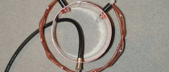
1) We need a piece of antenna cable, about 30 cm long.
2) Antenna connectors, the so-called F - connector and male - female connector.
F - connector and male-female
3) Tools: a knife, wire cutters, a calculator and, of course, a tape measure (or a ruler).
Theoretical part
indeed, if we err slightly against the truth and use the fact that the antenna within one range is indeed very broadband, then it works quite acceptably with a 50 or 75 ohm cable without special matching and tuning measures. But, if we look at everything in detail, it turns out that the antenna resistance very much depends on the shape of the frames and, of course, on their size. For example, the graph on the right shows the biquad impedance curves depending on the physical size of the frames. And we already know that the antenna is very broadband and can successfully operate not only at the resonant frequency but also near it. Therefore, biquadrat antennas are sometimes called not a resonant antenna, but a band antenna. Angle “a” is the physical angle between the vertical and the frame elements.
It will be interesting➡ How to connect an indoor antenna to a TV: practical tips
In this particular case, the angle is 45 degrees, that is, the shape of the frames are perfect squares. On the graphs you can see that if the perimeter of the frames exactly corresponds to the wavelength (the side of the square is equal to 0.25 of the perimeter), their impedance lies in the range of 50-60 ohms. If the side of the square is increased to 0.33, then the resistance increases to 120 ohms. It is calculated that the maximum gain of the biquad and the best directional properties will be when the length of the side of the square is equal to 0.375. Of course, the resistance increases many times over - up to 600-700 ohms, which is of course a lot even for our idea. The second graph, on the left, shows the dependence of resistance on angle “a”. If we consider the resistance graph with a square side length equal to 0.25 perimeter - directly resonant, but with an angle of the side to the vertical equal to 60 degrees, then we will find that the resistance of the biquadrat, or Kharchenko antenna, will not be 50 ohms, but 100!
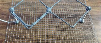
Large Kharchenko antenna.
Thus, we obtain an antenna with a circular radiation pattern with minimal difficulties in manufacturing and configuration. If one antenna is rotated 90 degrees not only in the horizontal, but also in the vertical plane, then we get an antenna with circular polarization and a circular radiation pattern. The simplest calculation will show you that to form an angle of 60 degrees between the vertical and the sides of the rhombus (with a perimeter equal to the wavelength, in our case 2000 mm), the height of the biquadrat should be 1000 mm, and the distance between the extreme points 866 mm.
The resistance of one such “biquadratin” will be 100 ohms. To obtain a circular radiation pattern, two biquads are placed at an angle of 90 degrees to each other and connected to each other using a quarter-wave transformer-phase shifter made of a cable with a resistance of 50 Ohms. Taking into account the shortening factor (for RG-58), this is a segment of 34.2 cm. You have probably already noticed my love for copper wire and sewer pipes? So it’s true, I don’t know a better material for modeling and practical manufacturing of VHF antennas.
Although, of course, everything described below can be replaced with your own structure made of wood, for example, or other available insulating material, and the wires with pipes or strips of tin or galvanized steel. Don't forget that there is an easy way to evaluate the quality of the antenna dielectric material.
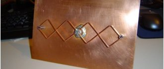
If I had not been a radio engineer in my youth, I would simply repeat the almost universally repeated phrase that the gain of the Kharchenko antenna is 6-8 dB. But since I understand the issue, I can say that the gain of one Kharchenko antenna (when it is 50 ohm) will not be more than 4 dB. In our case, when the resistance of one antenna is higher and the efficiency is better, maybe a little more. There will be no gain in gain from two antennas forming a circular radiation pattern, but we can safely say that in this antenna, let’s call it conventionally “two diamonds” (in appearance), the gain will be at least 4 dB in all directions.
So, let's move on to the design. Due to the fact that plastic tube sticks from McDonald's balloons are no longer suitable, the idea came to mind to use plastic sticks from children's skis, which the eldest grandson has already outgrown, and the youngest no longer wants red. The length and diameter are suitable, only the color let us down...