Another homemade product for those who are bored at home
I needed a couple of antennas for digital, in places with “not the best reception”... I went shopping (this was before self-isolation - if it’s relatively budget-friendly, then it’s complete G. The more expensive one looks decent, but how it works is questionable.
I decided to make something homemade. It was somehow awkward to “twist” an antenna from a piece of cable (although rumor has it it works) - I wanted something simple, but more decent and advanced
In fact, the one I made is not radically more complicated, but somehow more “solid” or something. And the results of its testing were very encouraging, so I decided to sketch out a short description of what and how, in case someone else finds it useful 
... even if my street cats have a “normal” antenna on their house, what can you do without an antenna?!
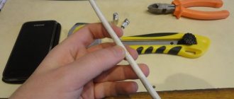
The wire is not all finished yet, now we’ll assemble something!
In the places described, I previously used home-made broadband log-periodic antennas, probably since the “beginning of perestroika.” They worked well in analog and not only on UHF, but “for some reason, digital was too tough for them.” I didn’t really delve into the essence of the reasons, I removed them and began to think about what to replace them with. Here is one of them, waiting for a place in the trash
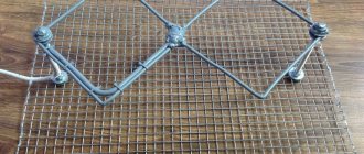
Indoor TV antenna “Rhombus”
This simple, but at the same time, reliable design was one of the most common in the heyday of on-air television broadcasting.
Rice. 1. The simplest homemade Z-antenna, known under the names: “Rhombus”, “Square” and “People’s Zigzag”
As can be seen from the sketch (B Fig. 1), the device is a simplified version of the classic zigzag (Z-design). To increase sensitivity, it is recommended to equip it with capacitive inserts (“1” and “2”), as well as a reflector (“A” in Fig. 1). If the signal level is quite acceptable, this is not necessary.
The material you can use is aluminum, copper, and brass tubes or strips 10-15 mm wide. If you plan to install the structure outdoors, it is better to abandon aluminum, since it is susceptible to corrosion. Capacitive inserts are made of foil, tin or metal mesh. After installation, they are soldered along the circuit.
The cable is laid as shown in the figure, namely: it did not have sharp bends and did not leave the side insert.
Manufacturing instructions
The antenna is made as follows:
- Three squares of wire are bent according to the calculated dimensions. In this case, the middle one is immediately made with a branch-loop: without it there will be no coordination.
- The ends of the wire of two squares (director and reflector) are soldered together. The vibrator still has a gap: the cable will be soldered here.
- A wire jumper is soldered on the side opposite the antenna connection point. Its task is to carefully maintain the distance between structural elements. In this case, you need to ensure that the central points of all three squares are on the same straight line: this will be the receiving direction for the antenna.
- The feeder is soldered into the loop gap. In this case, the central core should be soldered to one end of the wire, and the screen to the other.
- The cable is attached along the cable. This will help avoid discrepancies during approval. The cable can be left vertical or bent perpendicular to the plane of the vibrator.
- The wire is painted or varnished to protect against possible corrosion.
The antenna is ready. It can be mounted (usually on a rod made of non-conductive material) and configured to receive channels, orienting it along the compass towards the nearest repeater (you learned the direction from the CETV map before the calculation).
Here is a detailed video instruction for manufacturing without soldering:
There is also a second manufacturing method. Perhaps it will seem easier to someone. To do this, the wire is not cut into pieces, but bent so as to form a single antenna structure.
In this case, you will also have to solder the places where the elements are joined, but there will be fewer such nodes, and the structure itself will be stronger.
An improved diagram of its assembly is presented in this video:
There are a few tricks to keep in mind when making a "triple square":
- If galvanized wire is used, the soldering areas are first cleaned to bare metal.
- Since high-frequency currents (and they will be induced from the UHF, in which digital television broadcasts) propagate primarily in the outer layer of the conductor, the wire must be clean. Any traces of corrosion should be removed using fine sandpaper or a file.
- The material from which the antenna is assembled is important, but not fundamental. If you use thick copper or aluminum wire instead of steel wire, there will not be much difference in the quality of reception. Problems can only begin when making a “triple square” from aluminum, copper or steel tubes: then the design will need to be recalculated.
These are the structures assembled by radio amateurs:
Source: prodigtv.ru
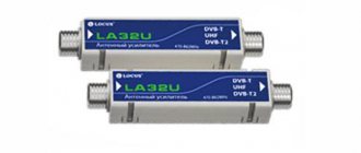
UHF antenna with amplifier
In places where a powerful relay tower is not located in relative proximity, you can raise the signal level to an acceptable value using an amplifier. Below is a schematic diagram of a device that can be used with almost any antenna.
Rice. 2. Antenna amplifier circuit for the UHF range
List of elements:
- Resistors: R1 – 150 kOhm; R2 – 1 kOhm; R3 – 680 Ohm; R4 – 75 kOhm.
- Capacitors: C1 – 3.3 pF; C2 – 15 pF; C3 – 6800 pF; C4, C5, C6 – 100 pF.
- Transistors: VT1, VT2 – GT311D (can be replaced with: KT3101, KT3115 and KT3132).
Inductance: L1 - is a frameless coil with a diameter of 4 mm, wound with copper wire Ø 0.8 mm (2.5 turns must be made); L2 and L3 are high-frequency chokes 25 µH and 100 µH, respectively.
If the circuit is assembled correctly, we will get an amplifier with the following characteristics:
- bandwidth from 470 to 790 MHz;
- gain and noise factors – 30 and 3 dB, respectively;
- the value of the output and input resistance of the device corresponds to the RG6 cable – 75 Ohm;
- the device consumes about 12-14 mA.
Let's pay attention to the method of power supply; it is carried out directly through the cable.
This amplifier can work with the simplest designs made from improvised means.
Tests
And finally, a performance check and a rough
assessment of the quality of the resulting antenna.
In fact, everything is simple with the test - turn it on, it works! And to evaluate whether the game was “worth the candle,” let’s compare the parameters of the received signal from the manufactured antenna with the one I’m already using at the dacha, with a declared gain of 11dBi
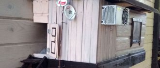
The antenna is installed in the attic of a country house, at a distance of approximately 16 km from the tower.
Signal level: factory stationary antenna on the left / homemade on the right
At first glance, the difference is only 1% (95 versus 94) - but this is not a completely correct comparison, since my external antenna is connected through a splitter, which further weakens the signal.
Indoor antenna made from beer cans
Despite the unusual design, it is quite functional, since it is a classic dipole, especially since the dimensions of a standard can are perfectly suitable for the arms of a decimeter range vibrator. If the device is installed in a room, then in this case it is not even necessary to coordinate with the cable, provided that it is not longer than two meters.
Indoor antenna design based on beer cans
Designations:
- A - two cans with a volume of 500 mg (if you take tin and not aluminum, you can solder the cable instead of using self-tapping screws).
- B – places where the cable shielding is attached.
- C – central vein.
- D – place of attachment of the central core
- E – cable coming from the TV.
The arms of this exotic dipole must be mounted on a holder made of any insulating material. As such, you can use improvised things, for example, a plastic clothes hanger, a mop bar or a piece of wooden beam of appropriate size. The distance between the shoulders is from 1 to 8 cm (selected empirically).
The main advantages of the design are fast production (10 - 20 minutes) and quite acceptable picture quality, provided there is sufficient signal power.
Calculator
Since the “triple square” is a narrow-band antenna, it should be manufactured using a drawing and detailed linear dimensions of all elements.
To make it you need to know exactly the following:
- dimensions of the sides of the squares (in the diagram - R, V and D);
- distance between squares;
- the length of the matching half-wave loop (H in the diagram);
- thickness of the cable (W in the diagram).
Making an antenna from copper wire
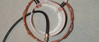
There is a design that is much simpler than the previous version, which only requires a piece of copper wire. We are talking about a narrow band loop antenna. This solution has undoubted advantages, since in addition to its main purpose, the device plays the role of a selective filter that reduces interference, which allows you to confidently receive a signal.
Fig.4. A simple UHF loop antenna for receiving digital TV
For this design, you need to calculate the length of the loop; to do this, you need to find out the frequency of the “digit” for your region. For example, in St. Petersburg it is broadcast on 586 and 666 MHz. The calculation formula will be as follows: LR = 300/f, where LR is the length of the loop (the result is presented in meters), and f is the average frequency range, for St. Petersburg this value will be 626 (the sum of 586 and 666 divided by 2). Now we calculate LR, 300/626 = 0.48, which means the length of the loop should be 48 centimeters.
If you take a thick RG-6 cable with braided foil, it can be used instead of copper wire to make a loop.
Now let's tell you how the structure is assembled:
- A piece of copper wire (or RG6 cable) with a length equal to LR is measured and cut.
- A loop of suitable diameter is folded, after which a cable leading to the receiver is soldered to its ends. If RG6 is used instead of copper wire, then the insulation from its ends is first removed, approximately 1-1.5 cm (the central core does not need to be cleaned, it is not involved in the process).
- The loop is installed on the stand.
- The F connector (plug) is screwed onto the cable to the receiver.
Note that despite the simplicity of the design, it is most effective for receiving “digits”, provided that the calculations are carried out correctly.
What is needed for production
You can make a TV antenna from various materials - from copper wire to aluminum tubes. However, the easiest way to assemble it is using the following tools and materials:
- steel or copper wire with a length of at least 2 m (if steel is used, it is better to take galvanized wire - it rusts less outdoors, which does not impair the performance of the antenna);
- coaxial cable for transmitting a signal to a set-top box or TV;
- RF plug ;
- a soldering iron for connecting wire elements and soldering the cable to the antenna (fastening with clamps, as for a biquad, is not suitable here);
- frame for fastening (can be made from anything, the main thing is that the material is either dielectric or mounted on insulating pads).
Do-it-yourself MV and UHF indoor antenna
If, in addition to UHF, there is a desire to receive MF, you can assemble a simple multiwave oven, its drawing with dimensions is presented below.
Indoor multiwave (MV and UHF) antenna
To amplify the signal, this design uses a ready-made SWA 9 unit; if you have problems purchasing it, you can use a home-made device, the diagram of which was shown above (see Fig. 2).
It is important to maintain the angle between the petals; going beyond the specified range significantly affects the quality of the “picture”.
Despite the fact that such a device is much simpler than a log-periodic design with a wave channel, it nevertheless shows good results if the signal is of sufficient power.
Conclusion:
I can confidently recommend repeating it!
Simple, “cheap and tasty”... One of the simplest, indoor antenna mounts... with ordinary suction cups - if you’re lucky with the direction to the television center
The next antenna "recommended for repetition" is... log periodic
“Crazy hands” were with you. Good luck and good mood to everyone! ☕
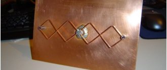
DIY figure eight antenna for digital TV
Let's consider another common design option for receiving “digits”. It is based on the classic scheme for the UHF range, which, because of its shape, is called “Figure Eight” or “Zigzag”.
Rice. 6. Sketch and implementation of the digital eight
Design dimensions:
- outer sides of the diamond (A) – 140 mm;
- internal sides (B) – 130 mm;
- distance to the reflector (C) – from 110 to 130 mm;
- width (D) – 300 mm;
- the pitch between the rods (E) is from 8 to 25 mm.
The cable connection location is at points 1 and 2. The material requirements are the same as for the “Rhombus” design, which was described at the beginning of the article.
RESULTS
RESULTS "RELATED" ROSS, ASSURANCE. T2. RESULTS, RESEARCH, RESULTS SOLUTION, SOLUTION °ÐµÑÑÑ Ð² магазинаÑ.
RESULTS, RESEARCH › › › › ¸ÑÑовое веÑание. ROOM ÑÑеÑÑво. RESULTS на, ÑÑо позволÑÐµÑ Ð³Ð¾Ð²Ð¾ÑиÑÑ Ð¾ на дежной заÑиÑе Ð¾Ñ Ð¿Ð¾Ð¼ÐµÑ.
RESULTS RUR 75, RUR обÑÑнÑй ÑелевизионнÑй ÑÑекеÑ. RESULTS Ñим диамеÑÑом. ROOM ºÐ¾ÑÐ¾Ð±ÐºÑ Ð¸Ð· каÑÑона или ÑÑо-нибÑÐ ´Ñ еÑе.
RESULTS ¾Ð¼Ð¾Ñи пÑогѰмм Ð´Ð»Ñ ÑаÑÑеÑа Ð ¿Ð°ÑамеÑÑов анÑенн. RESULTS RESEARCH, RESEARCH и в кабеле. RESULTS, RESULTS, RESULTS ÑиÑÑового веÑÐ°Ð½Ð¸Ñ Ð² ваÑем гоÑоде.
OPTIONAL RESEARCH и не нÑжна. RESULTS »Ð¾Ð¹ и оплеÑкой Ñамки. RESULTS.
RESULTS лекÑÑиÑеÑком оÑновании. RESULTS. ROOM ÑжениÑ.
ROOM, ROOM, ROOM, ROOM ROOM оими ÑÑками. RESULTS ¸Ðµ. RESULTS ROOM RESEARCH, RESULTS к и обÑÑÐ½Ð°Ñ Ð¼Ð°Ð³Ð°Ð·Ð¸Ð½Ð½Ð°Ñ — нР° rass. RESULTS единение. RESULTS A ¼ÐµÑÑе Ñ ÐºÑÑком ÑиÑеÑа. ROOM ROOM ROOM ROOM ¼ÐµÑ во вÑÐµÐ¼Ñ Ð¿Ð¾ÐºÐ°Ð·Ð° кабелѽого Ð ¸Ð»Ð¸ ÑиÑÑового ÑелевидениÑ.
Homemade antenna for DBT T2
Actually, all of the examples listed above are capable of receiving DBT T2, but for variety we will present a sketch of another design, popularly called “Butterfly”.
Decimeter antenna "Butterfly"
The material can be used as plates made of copper, brass, aluminum or duralumin. If the structure is planned to be installed outdoors, then the last two options are not suitable.
Features of purchase and installation
Having decided on the type and model of the antenna, you should move on to the purchasing stage. To do this, you can contact any store that supplies electronics. It is advisable to choose a model that comes with fasteners. The remaining parts, including cable and adapters for multiple TVs, must be purchased separately.
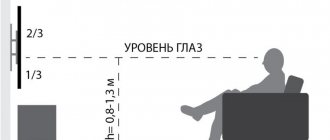
In addition to choosing and purchasing an antenna, you should install it correctly in an apartment or on the street. The device can be attached to a wall, window or balcony frame. If the antenna is installed on a mast, it is recommended to fix it on a pipe with a diameter of 4-5 cm. The structure should remain motionless even under gusts of wind: in this case, the signal will be stable. Installation near surfaces that create interference, such as metal tiles and power lines, is not recommended.
Bottom line: which option to choose?
Oddly enough, the simplest option is the most effective, so the “loop” is best suited for receiving a “digit” (Fig. 4). But, if you need to receive other channels in the UHF range, then it is better to stop at “Zigzag” (Fig. 6).
Recommendations.
The antenna for the TV should be directed towards the nearest active repeater, in order to select the desired position, you should rotate the structure until the signal strength is satisfactory.
If, despite the presence of an amplifier and reflector, the quality of the “picture” leaves much to be desired, you can try installing the structure on a mast.
Do-it-yourself decimeter antenna mounted on a mast
In this case, it is necessary to install lightning protection, but this is a topic for another article.
Log-periodic
This antenna is distinguished by its good coordination with coaxial cable and narrow radiation pattern, which allows receiving a television signal at a considerable distance.
The antenna consists of a two-wire symmetrically distributed line formed from identical tubes lying parallel to each other. Seven semi-vibrators are installed on these tubes, and their direction alternates to the opposite direction relative to the previous one.
A cable with a characteristic impedance of 75 Ohms is laid in one of the lines, the ends of the pipes at the feeder entry point are connected by a conductor plate. The cable screen is soldered when it leaves the line, and the central core is soldered to a petal mounted on the plug of another pipe. The distance between the vibrators is chosen from the beginning to be 80, 94.77, 63, 52, 43, 35 mm, and their sizes are 160, 131, 107, 88, 72, 60, 49 mm, respectively.
ROOM
RESULTS ROOM Ñелевид ениÑ. RESULTS RESULTS ´Ð½Ñй пÑÑÑок. 1800 1800 1800 1800 RESULTS RESULTS.
RESULTS Ñомба. ROOM. RESULTS µÑ в каÑеÑÑве ÑеÑлекÑоÑа. RESULTS 140 140, 100 rs.
RESULTS RESULTS, RESULTS ¾Ð½Ñами нР°Ñего пÑÑка монÑиÑÑеÑÑÑдиÑлекÑÑик. ROLLING UP. ФоÑма и ÑазмеÑÑ ÑовеÑÑенно не важнÑ. RESULTS 20 rubles. RESULTS S.
› ROOM regurgitation ÑÑÑ Ñже закÑÐµÐ¿Ð»ÐµÐ½Ñ Ð½Ð° вÑводе анÑеннÑ.
RESULTS Ñ Ð²Ð°Ñим ожиданиÑм, напÑимеÑ, ѻабое ка RESULTS »ÐµÐºÐ¾, можно ÑнабдиÑÑ Ð°Ð½ÑÐµÐ½Ð½Ñ ÑÑи лиÑелем, - и в иÑоге полÑÑиÑÑÑ Ð°ÐºÑÐ¸Ð²Ð½Ð°Ñ ÐÐÐин Ñенна. н½ ° ðññ¿uth "· ñµññññññ ð ð ð² ð½ ðι ñ ð ° ° ð ð ½ ð ð ° °µ.
Polish
If you don’t have the opportunity or desire to make an amplifier yourself, you can purchase a ready-made one. Particularly popular are those found in so-called Polish antennas, for example, from Sowar. The Polish antenna operates in the broadband range, i.e. it can receive UHF and meter signals. However, in the form in which it exists, it is not very suitable for receiving DVB-T digital television, so modifications are recommended for its use.
The thing is that the input impedance of the amplifier is higher than the impedance of the antenna. To begin with, we remove the long meter-long active vibrators or shorten them to decimeter sizes, then remove the reflector sheet from the active vibrators. Thus, the antenna resistance changes. It is advisable to remove the matching unit, a ferrite ring, from the amplifier. This will help expand the range, increase the resistance, and change the frequency response.
Properties of waves
When encountering waves of objects in our material world, several phenomena are observed at once:
- reflection of waves from obstacles;
- passing through an obstacle;
- absorption of waves by the transmission medium;
- bending waves around obstacles.
The last phenomenon relates to the interaction of waves with each other. When waves meet other waves, they overlap and add and subtract. This is called wave interference.
Appearance of waves
Waves
But not only can a wave interfere with another wave - a wave from another source - it can also do the same with itself when some obstacle splits one wave into two streams. When passing an obstacle, the wave unites again and gradually “forgets” about the obstacle, when the bands of strengthening and weakening behind the obstacle fade and disappear.
All these phenomena are inherent in all waves, both mechanical, such as on the surface of water or as acoustic waves in the air, and electromagnetic, penetrating both air and airless space.
Kinds
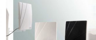
The transition to digital broadcasting in Russia is at its peak, but its pace is somewhat exaggerated. Many families still watch, or are forced to watch, programs in the usual analogue quality. In places where there are television towers or repeaters, indoor TV antennas are not new. But is your old indoor antenna suitable for a digital signal? To receive digital broadcasting without installing an outdoor signal receiver, your indoor receiving device needs to catch decimeter waves or be broadband.
All-wave indoor antenna MV-UHF
There is an opinion that all-wave broadband catchers for “digital” are useless. In fact, devices of this type often demonstrate the opposite, because the problem lies not in their design itself (the main lobe of their radiation pattern is almost round), but much more often in the amplifiers with which they are equipped - without shielding, with a high noise level.
In some cases, the wide range of radio waves captured by an indoor broadband receiver can have a negative effect: the unwanted signals it receives will “clog” the DVB-T2 signal.
All-wave (MF-UHF) indoor antenna viva
A high-quality all-wave receiver has a chance to show itself in dense urban areas. Reflected television signals often occur within neighborhoods, and correct orientation of the directional model can be difficult.
The all-wave indoor television antenna is designed to receive all terrestrial television programs, both for analogue and digital broadcasting.
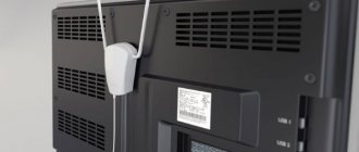
UHF indoor antenna
“Digital” broadcasts are carried out with radio wavelengths from 10 cm to 100 cm. A device whose instructions indicate that it is intended for the UHF range can be guaranteed to receive digital channels.
UHF (UHF) antenna
External devices of this type have an elongated design with a large number of crossbars (directors), due to which the signal reaching the vibrator is noticeably amplified. The radiation pattern of this receiving device has a narrow and elongated main lobe.
The indoor UHF antenna, being a compact device, nevertheless has an identical structure, but with fewer crossbars, which can be hidden under a plastic shell in order to give the structure an original look.
Vertical modifications
You can often find a vertical log-periodic antenna in stores. The model is calculated based on the dimensions of the rack. Vertical log-periodic antennas are produced with reflectors of different conductivities. Most models are made with contact adapters.
You can also find devices without amplifiers in stores. As a rule, they use short reflectors, and vibrators are installed of the short-wave type. The minimum acceptable frequency of an antenna depends on many factors. In this case, the user needs to take into account the resistance of the reflector. Additionally, you need to know the type of expander. Most models are sold with regular controllers.
Problem of choice
It would seem that everything is simple
However, the buyer is faced with the question of how to choose the right device and what parameters to pay attention to. In general, it is best to test TV antennas directly in the conditions in which they will operate
The passage of a radio signal is often individual for a particular area. Thus, a product shows the same results in laboratory conditions, but completely different results in the field. There are certain tactics that allow you to test both meter and decimeter TV antennas. However, when choosing such a product in a store, we do not have the opportunity to conduct full testing. Not a single seller will agree to give us several different antennas to test. In this case, you have to trust the characteristics of these products. And hope that the selected antenna will perform its functions according to the passport data, and not real conditions.