Making your own antenna is a good idea. You don’t have to spend money on buying a finished product, and you don’t want to attract intruders with a beautiful dish or a high-quality radio installation.
If you have a private house or a summer cottage with a small garage, you can make your own television antenna in literally 20-30 minutes. TV is not only a source of information, but also a special atmosphere of comfort and homeliness.
Types of TV antennas
A television antenna is a device specifically designed for receiving broadcast television signals that are transmitted at frequencies from 41 to 250 MHz in the VHF range, and from 470 to 960 MHz in the UHF group.
There are two types of television antennas:
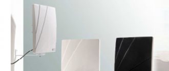
- Internal – located on top or next to the TV;
- External - installed on the roof or attic of the house.
Outdoor antennas are more complex to manufacture and install, but such devices are necessary for adequate reception in peripheral areas remote from television stations.
Antenna devices are also divided into:
- Active, which are complemented by an amplifier and require connection to an electrical power source;
- Passive, which amplify the signal only due to design features.
An outdoor TV antenna is a high input power device and has a unidirectional radiation intensity so its far end must always face the broadcast station.
Based on the wavelength that television antennas are capable of receiving, they are divided into three groups:
- MV antennas - such devices receive very long meter waves, the size of which can be from 0.5 to 1.5 m;
- UHF antennas - these devices operate in the decimeter range, in which the wavelength is in the range from 15 to 40 cm. It is in this coverage that digital television (DTV) is supplied;
- Broadband antennas are a hybrid design in which both VHF and UHF elements are installed. Such radio installations are used to receive digital and analogue broadcasts simultaneously.
The most commonly used design is an outdoor television antenna based on a log-periodic dipole matrix. Such products consist of several half-wave elements consisting of metal rods. They act as resonators in which energy is stored by radio waves, which cause electrons to move and create stable waves of oscillatory voltage. An antenna can have a different number of rod elements: the more, the higher its gain.
Another popular design, used primarily for UHF reception, is the reflective TV antenna. Such a device consists of a vertical metal screen with several dipole elements installed in front of it.
The television broadcast bands that must be covered by a single antenna are too wide in frequency, so either separate antennas or combined devices are used for the VHF and UHF bands. In such designs there are two types of elements: long elements that pick up the MF (these are located at the rear of the antenna boom and often function as a log-periodic antenna) and short elements that pick up the UHF broadcast (these are located at the front of the boom).
When you listen to the radio, you notice that local channels can be easily tuned in the FM or VHF range, but you won’t be able to catch distant foreign broadcasts on them; to do this, the receiver needs to be switched to MF and HF mode.
This suggests that meter, medium and short waves are well transmitted over long distances, while ultrashort and decimeter signals have a small coverage area. However, the disadvantage of the UHF range in which our digital television operates is minimized thanks to two things:
- Firstly, the presence of a large number of towers;
- Secondly, the ability of large objects to reflect the signal.
If you live in a private house next to a high-rise building, then it is more correct to point the TV antenna not at a distant tower, but at a neighboring house, which perfectly reflects the waves. The correct choice of direction largely determines the quality of the TV signal.
Bottom line: which option to choose?
Oddly enough, the simplest option is the most effective, so the “loop” is best suited for receiving a “digit” (Fig. 4). But, if you need to receive other channels in the UHF range, then it is better to stop at “Zigzag” (Fig. 6).
Recommendations.
The antenna for the TV should be directed towards the nearest active repeater, in order to select the desired position, you should rotate the structure until the signal strength is satisfactory.
If, despite the presence of an amplifier and reflector, the quality of the “picture” leaves much to be desired, you can try installing the structure on a mast.
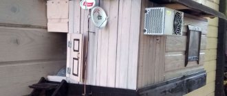
Do-it-yourself decimeter antenna mounted on a mast
In this case, it is necessary to install lightning protection, but this is a topic for another article.
Materials and calculations
How and from what items and materials can you make an antenna at home? Let's look at the TOP 5 most interesting options:
- Powerful coaxial cable antenna;
- All-wave antenna made of wire;
- "Butterfly";
- "Eight" or zigzag;
- Antenna made from beer cans.
A tube, rod or wire made of copper or aluminum are excellent materials for making an antenna. They are flexible, bend well and hold their shape well. You can use any conductive metal products: wires, corners, rods, strips, etc.
Coaxial cable has the same properties as copper cable, but is much cheaper, and, in addition, coaxial is also mechanically strong, which is important for antenna design. To save money, you can use pieces of wire that are available in your household or buy them in the hardware store.
First of all, let's decide on the size of the antenna. The antenna cable length (L) is calculated depending on the broadcast frequency. To calculate we need two values:
- The speed of wave propagation in vacuum is ≈ 300 million m/s;
- F – reception frequency (digital TV signal frequencies are usually in the range of 500-800 MHz).
If we take the frequency parameter in MHz, then the desired wavelength value will be in meters. The calculated speed of light parameter is 300. The wavelength in the cable can be calculated using a simple formula:
L = 300/F
Calculation example: let digital broadcasting be carried out at an average frequency of 610.5 MHz. Then the average wavelength = 300/610.5 = 0.491 m. This is exactly what the length of the antenna loop should be.
To receive a digital signal, it is not necessary to accurately calculate the wavelength; you can simply make the product design more broadband.
Selecting a TV cable
Even an excellent TV and correctly placed F-plugs on the ends of the cable will not be able to provide high quality images on the screen when using a low-quality television cable. And the question arises, which antenna cable is better for connecting a TV and what criteria should you use to choose it?
TV cable device
Let's look at how a modern television coaxial cable works using the example of a CAT-703 cable.
Along the center of the entire length of the coaxial cable runs a copper or steel wire core covered with a copper layer. This core is covered with a layer of insulation made of dielectric material. The insulation is covered with a shielding copper or aluminum foil braid, which acts as a second conductor. To protect against mechanical and climatic influences, the cable is covered with a sealed protective sheath.
Inexpensive cables use only aluminum braid, budget cables use copper, and expensive cables use aluminum and copper at the same time, as shown in the photo.
How does current flow through an antenna cable?
To consciously choose a good antenna cable, you need to imagine how high-frequency current flows. Current in an electrical network flows across the entire cross-section of conductors.
The high-frequency current of a television signal flows according to a different law. Everyone knows how laundry is spun in the centrifuge of a washing machine: the higher the speed, the stronger the centrifugal force acts on the water, and it is better removed from the laundry, the laundry becomes drier. Many people experienced the effects of centrifugal force on their own bodies in childhood while riding on carousels.
The high-frequency current of the television signal flows in the antenna cable in a similar way. The higher the frequency, the closer to the surface of the conductor it flows. The skin effect appears. If we take, for example, a copper wire with a diameter of 10 mm and a copper tube of the same diameter with a wall thickness of 1 mm, then a current with a frequency of 1000 MHz will flow through them with the same losses!
Therefore, in antenna cables used for military and space equipment, to reduce signal loss (attenuation), the central core and cable braid are often coated with a thin layer of silver and even gold. This is a very expensive pleasure, and such cables are not used in everyday life.
Due to the small magnitude of the television signal in the antenna cable and its high frequency, it is not possible to determine its presence in the cable, much less carry out measurements at home without specialized expensive instruments. Only connecting the antenna cable to the TV will determine the presence and quality of the television signal.
TV cable marking
The most widely used antenna cables on the market are coaxial antenna cables from different manufacturers with a characteristic impedance of 75 Ohms, brands RG 6U, SAT 50, SAT 703B and DG 113, which can be successfully used for receiving analog and digital television signals up to transmitting them from a satellite antenna with a frequency of up to 2. 15 GHz. The brands are listed in order of increasing quality of the antenna cable - reducing signal loss (attenuation) during transmission. The marking (designation) must be applied to the antenna cable sheath along its entire length every meter with a digital meter mark.
This antenna cable marking indicates the following:
- CABLETECH – manufacturing company CABLETECH (China).
- RG 6U/48 – cable brand.
- HIGH QUALITY COAXIAL CABLE – high quality coaxial cable.
- 75 OHM – characteristic impedance 75 Ohm.
- 055M – meter mark, with each meter the mark changes by 1.
How to choose a TV antenna cable
The antenna cable sheath must be marked as shown above. The antenna cable must have a characteristic impedance of 75 Ohms (all televisions and switching devices are designed for this impedance - amplifiers, splitters, set-top boxes for receiving DVB-T2 digital channels). The outer diameter of the antenna cable sheath must be at least 6 mm. Central core and shielding braid made of electrical copper. Antenna cables of the SAT 703B and DG 113 brands meet these requirements. The RG 6U cable has a central steel core, galvanically coated with copper, an aluminum foil screen and copper alloy braiding, this is a budget option.
It is impossible to describe all the television cables on the market, but the information presented is quite enough for you to make the right choice yourself.
Manufacturing and arrangement
Today, all television is presented in digital format; analogue will soon be completely abandoned. Old antennas practically do not function with DVB signals, so you need to create a decimeter antenna.
Digital TV transmission in DVB-T2 format is carried out in the UHF range, and since the signal is broadcast digitally, its reception will always be in good quality, or it simply cannot be caught, and there will be no signal at all. Interference, distortion or unclear picture - this is typical only for analog television.
DVB (Digital Video Broadcasting) encoding is insensitive to electromagnetic interference, however, if the air is heavily polluted, signal mismatch may occur, which can cause the image to freeze or completely crumble. Therefore, it is more efficient to place the antenna outside the house: outside the window, on the roof, on the balcony.
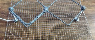
To reduce the amount of interference, a reflector (reflector) can be built behind the antenna. The simplest materials with a metallic tint are suitable for the antenna design: foil, coffee or juice packaging, tin can, CD, etc. In order for the reflector to have a narrowly targeted effect, the shape of the reflector can be made parabolic. Although this is more relevant for analog receivers, reflectors also help out when the digital signal level is weak.
And the last piece of advice: experienced engineers recommend soldering all antenna connections, and not just twisting or screwing them, as over time they will oxidize and affect the quality of reception. It is better to coat external antennas made by yourself with paint; it will more reliably protect your structure from adverse weather factors.
To connect antenna elements, it is better to use soldering machines with a power of 36-40 watts, flux and soft solders.
Useful recommendations when choosing
- If you are using an expensive TV model with a screen diagonal of 32 inches or more, it is better to purchase a good external antenna for high-quality reception. Keep in mind that the internal model is not capable of fully providing TV equipment with all available channels.
- The outdoor model becomes ideal if there are several TVs in the house. If the house is located at a significant distance from the TV tower, the use of an amplifier will be required. But you should not connect it if the room is close to the broadcast station - the amplifier will be overloaded, which will cause poor picture quality with distortion.
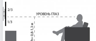
- Use indoor modifications when the building is located 10-15 km from the TV tower. When choosing an internal device, give preference to directional models.
Indoor TV antennas are suitable as an alternative when high-quality reception of all available channels is not important to the user.
Remember that purchasing even the latest state-of-the-art antenna does not guarantee 100% reception of TV signals and high-quality display of all available channels. For full reception, take into account a number of nuances, including the television model, the tuner of which must comply with DVB-T2 standards.
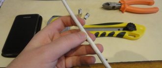
Coaxial cable antenna
To create this version of the antenna, you will need about 0.5 m of the most common television cable marked “RK-75”. One end of the insulated wire needs to be stripped to connect to the TV socket (put on the F-connector and an adapter for connecting to the TV), and on the second we will create a round antenna.
Step back 5 cm from the edge and remove the top layer of insulating impregnation compound. Then remove the winding from the central conductor of the cable and tightly twist the remaining wire strands into one bundle.
Next, step back 22 cm from the prepared edge of the cable and remove 2 cm of outer insulation along with shielded foil and braid, without affecting the insulation of the central core.
From this point, measure the next 22 cm and cut through the outer layer of insulation to the shielded foil. Now you need to connect the cable into a ring: to do this, we confidently screw the first prepared end to the newly created cut. That's all - you have in your hands a powerful antenna made of coaxial cable, made by yourself.
Connect it to the TV and start tuning channels. This antenna is considered a good option for receiving digital television. It is better to install the antenna outside the window and on the side of the TV tower, since the walls of the building can drown out the desired signal. You can experiment with its position yourself.
All-wave antenna
A TV antenna can have different shapes. For example, from copper wire with a diameter of 2-5 mm, you can build an all-wave antenna in the form of two versatile elements. Such devices are frequency independent, so they are very popular among summer residents. A CHNA device can be built in literally an hour and receive a good signal level far from television centers.
For this you will need:
- Enameled copper wire;
- 2 metal structures in the shape of an isosceles triangle;
- 2 wooden or plastic slats.
Instead of metal triangles, you can use elastic foil laminate, from which you will need to cut the triangles (or leave the copper coating in a triangular shape).
The width and height of the antenna must be identical. The blades are installed at right angles and fixed with a soldering iron. The CNA antenna cable must be laid to the point of zero potential, which is located at the intersection of the cable with the vertical guide. Moreover, it must be tied with a tie, and not soldered.
The distance between adjacent wire threads should be 25-30 mm, and between the plates - no more than 10 mm. It is better to install the antenna structure inside the window at 150 cm. The signal catcher in the form of two expanded elements, which you just made yourself, will confidently receive all UHF and HF channels. If you live in an area with poor signal levels, it would be advisable to supplement such a device with an amplifier.
Why you don't need to strive for an antenna with an amplifier
It has been noticed that the word “Amplifier” has some magical properties! And when a person chooses an antenna, he gives preference to just such, active antennas. Why is this a wrong point of view?
- In the area of reliable reception, the amplifier can lead to the fact that your TV/set-top box will not receive anything at all! Reason: over-amplification of the signal!
- The amplifier amplifies not only the useful signal, but also radio noise. And it is the antenna design that pulls out the useful signal!
- The amplifier is always the weak link in the antenna design. It fails, it is hit by a thunderstorm, it oxidizes from moisture. As a result, periodic intervention in antenna repair is required.
- It is necessary to provide power to the amplifier located in the antenna, and this is another additional weak link; the adapters fail and require replacement. In addition, another connection point, socket or USB port is required, and this is not always convenient!
- If you connect several TVs to one antenna, this is much easier to do with an antenna that does not have an amplifier.
When do you need an amplifier?
- If the total length of the television cable exceeds several tens of meters.
- If you live at a great distance from the transmitting tower, in an area with a weak signal, and the design of the antenna itself does not allow you to “pull” the signal to the required level.
Conclusion! - If in the place where you live it is possible to confidently receive a signal on an antenna without an amplifier, always strive for an antenna without an amplifier!
A simple antenna for receiving digital TV
Another useful type of home antenna for the dacha is the “butterfly”. This is a very simple design, to create which you will need:
- Board or plywood about 60 cm long and 7 cm wide, thickness about 20 mm;
- Shielded copper wire with a 4 mm core cross-section;
- Coaxial cable “RK-75”;
- Washers, screws, soldering iron.
Below we provide a marking diagram according to which you need to make the base of the butterfly antenna.
Scheme
After this, prepare 8 pieces of copper wire, each 37.5 cm long. Step back 17.75 cm and remove 2 cm of the insulating layer in the center of each piece. Give them a V-shape so that the ends of the elements are at a distance of 7.5 cm from each other (this shape is considered optimal for high-quality and clear TV signal reception).
The next step is to prepare two more wire elements about 22 cm long. Mark each element into 3 equal parts and strip the wire insulation between the resulting sections.
We will need two more small pieces of wire to connect the antenna to the socket.
Now all that remains is to simply assemble all the prepared elements into a single structure and solder the cable to the plug.
This is how you can easily make your own effective butterfly antenna for receiving digital television.
Figure-of-eight antenna
The next option for creating a simple UHF television antenna is named after the shape of its design, “figure eight” or “zigzag”. Such a device will reliably pick up the signal even in a remote village.
In order to make an outdoor antenna for digital television with your own hands, you will need:
- Amplifier (you can use any old one);
- 2 pieces of copper wire (180 cm each);
- Plate (wood or metal) 15*15;
- TV cable;
- Iron mast for raising the antenna.
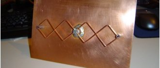
First of all, we create the body of the catcher: from copper wire we form two rhombuses with an optimal side size of 45 cm each. We attach the ends of the two elements to the plate: we form a ring from the core and slightly flatten it, screw it with bolts or solder it using a soldering machine.
We connect the amplifier and insert the cable plug into the connector. In general, that's all. All that remains is to install the finished structure on an elevated mast, which must be firmly dug into the ground.
To make an outdoor antenna for a TV, any conductive material of the appropriate cross-section is suitable: copper or aluminum tubes, strips or a profile element with a thickness of 1 to 5 mm. The main thing is to give the antenna body the correct shape.
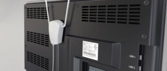
How to set up an indoor TV antenna yourself
It is certainly clear that street antennas pick up signals from not only analog programs, but also digital ones, many times faster and better: in open space, radio waves propagate unhindered, but within four walls it is more difficult for them to penetrate to the TV. But even indoor receivers, if they are properly configured, are capable of receiving a high-quality signal.
- Install your receiver on the TV cabinet or on a windowsill next to it. Plug the plug into the appropriate connector, then search and configure channels. If there are few programs available, try moving the antenna to the sides, up and down.
- If your antenna has “mustaches,” then you can achieve image quality by changing their height, as well as adjusting the angle between them. Once the best signal is received, be sure to fix the device in that position.
- Surely you have noticed that in your presence the antenna picks up the signal better, and as soon as you release the device, snow and hissing form. This happens due to the fact that waves are reflected from you, which are to be found in space.
- Some antennas need to be placed separately from the TV, especially if they are configured to receive a digital signal, and when your TV has a built-in T2 module. In such cases, it is important to achieve better capture and then monitor the programs.
- If the indoor antenna has a built-in amplifier, then there must also be a regulator. Twist it to find a position that improves the signal on your TV, then leave it there.
Modern antennas, even with an amplifier, operate silently.
GOOD TO KNOW!
If your antenna finds a ton of channels in a foreign language, you don’t have to try to tune in to the perfect signal. To do this, it is important to know the specific parameters of the radio wave, and it is also desirable to know the language of foreign broadcasting.
Beer can antenna
Ether antenna devices can be created from many simple materials that are used in household use, even from ordinary cans in which carbonated drinks are sold. Such a mini-receiver will not be very powerful, but you can pick up about 7 channels, not only in the UHF range, but also in the longer one - VHF.
There is one important condition: the cans must be smooth, not ridged, clean and dry. The essence of this design is very simple: you just need to solder 2 cans to the cable and place them on opposite sides on a wooden base.
The number of cans can be used differently; it is believed that it is optimal to create 3 or 4 lines of cans, since 1-2 lines pick up the signal weakly, and more than 5 lines are difficult to coordinate. In addition to cans, you need to prepare the following materials:
- About 5 meters of ordinary TV cable marked “RK-75”;
- Wooden or plastic base structure;
- Several self-tapping screws, electrical tape, and a soldering iron.
First you need to prepare the TV cable: step back 10 cm from the edge, make a shallow cut and remove the top layer of insulation. Carefully twist the inner braided screen into a single bundle. On the same side of the cable, remove the plastic insulation and expose the central core. A plug must be connected to the opposite end of the cable.
Next, we will need to connect the coaxial cable to the banks. To do this, it is better to use small flea screws for drywall: screw a twisted cable braid to one can, and a copper core to the second can. For better contact, connections can be soldered.
Now you should secure the cans to a wooden base plate. This can be done using ordinary adhesive tape, electrical tape or a glue gun; you can even use an ordinary clothes hanger or any flat structure at hand. The main thing is that the metal cans are of the same shape, the same size (volume) and are located strictly on the same line. The distance between the sheet metal elements, as well as the location of the antenna installation, is selected experimentally.
You can improve the design by creating a grid of several lines with banks, and if there is such an opportunity, then connect an amplifier. If a homemade antenna made from beer cans is placed on the street, then its elements will have to be hidden in larger plastic bottles.
The length of the cable affects the signal attenuation: the longer the cord, the more the on-air transmission is attenuated. This is especially true for receiving meter waves.