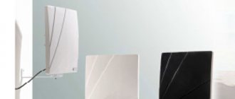
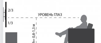
From 2021, Russian television is switching to digital broadcasting. The image quality is getting better, but it does not exclude glitches. In addition to a good digital set-top box, you will need to purchase an antenna that will prevent problems from occurring. Residents of city apartments should choose an indoor antenna for digital television, which is mounted indoors.
Types of UHF-T2 devices for high-quality terrestrial television reception
You most likely will not be able to watch TV on a digital DVB-T2 signal at your dacha using a standard indoor antenna. Here you will need a digital antenna. However, you should know that there are no “digital” antennas as such. And there are:
- terrestrial antennas;
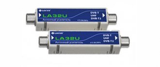
- antenna amplifiers;
- coaxial cables.
So, if there is a signal matching board (balun) on the coaxial antenna cable, then this is a passive version of the antenna. And if there is also an amplifier with a power supply, then the antenna is active. The division of such antennas into active and passive types is the very first, main classification.
In addition, the following are suitable for receiving a digital signal in the country:
- decimeter antennas (UHF);
- broadband antennas (MV-UHF).
In this case, the recommended format is multi-director, which allows you to point the antenna directly at the repeater. (The most effective is the broad-directional type of antenna.)
Meter wave range
If desired, you can adapt an antenna for decimeter waves to receive a digital signal. However, if there is only a complex antenna available for both the meter range (MV) and the decimeter range (BMW) - the so-called indoor multiwave, then you can use it too. Here it will be quite simple to connect the SWA 9 modular unit to the antenna. It is a regular DVB-T2 antenna signal amplifier.
The meter range antenna is not designed to receive a digital signal.
UHF (UHF)
In general, a digital television signal broadcast in the DVB-T2 format is transmitted in the same long-wave range as UHF waves.
The difference in practice is that in the case of a digital signal it is impossible to increase the range of one’s own location in relation to the repeater due to deterioration in picture quality. The signal is either present or it is not.
Also a characteristic feature of “digital” is the high quality of the transmitted image (of course, if it is present).
Any UHF antenna is suitable for receiving a DVB-T2 signal.
Features of decimeter antennas
UHF antennas come in different types and shapes. To obtain increased antenna array sensitivity, pay attention to several indicators:
- Standing Wave Ratio (SWR). For the best reception, the antenna resonator frame must be a multiple of the wavelength (λ), while the SWR will tend to 1. The closer to this figure, the better the reception. SWR is a relative value and has no unit of measurement.
- Gain factor (GC). It is measured in decibels. The number shows how many times the receiving device amplifies the received signal. To calculate the multiplicity, a special table is used. A gain of 7 decibels indicates an increase in power by 5 times, 10 dB by 10 times, 20 dB by 100 times.
- Noise figure (NF). Also measured in decibels, but applied to the noise surrounding the wanted signal.
- Amplitude-frequency response (AFC) – shows the ratio of the amplitude of the input and output signals over the entire range of operating frequencies. It is important that it is uniform at decimeter radio frequencies.
Principle of operation
To select the SWR for different frequencies of the desired range, manufacturers supply the arrays with a variety of resonator pins, each of which has individual dimensions and is adapted to a specific wavelength. The distance between the resonators and the reflector is also made a multiple of the length of the received radio waves, for example, 0.25λ.
To increase the likelihood of receiving a peak radio wave signal, the resonators are installed in two rows. The bottom one is shifted relative to the top one so as to cover the gaps between the pins of the top row.
On some antenna models, a reflector is installed behind the resonators - a mesh or solid metal plate. Its purpose is to reflect the waves arriving at it to one point to enhance the reception characteristics.
Photo
In the photo below you can see various homemade homemade TV antennas:
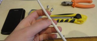
Coaxial cable antenna
To create this version of the antenna, you will need about 0.5 m of the most common television cable marked “RK-75”. One end of the insulated wire needs to be stripped to connect to the TV socket (put on the F-connector and an adapter for connecting to the TV), and on the second we will create a round antenna.
Step back 5 cm from the edge and remove the top layer of insulating impregnation compound. Then remove the winding from the central conductor of the cable and tightly twist the remaining wire strands into one bundle.
Next, step back 22 cm from the prepared edge of the cable and remove 2 cm of outer insulation along with shielded foil and braid, without affecting the insulation of the central core.
From this point, measure the next 22 cm and cut through the outer layer of insulation to the shielded foil. Now you need to connect the cable into a ring: to do this, we confidently screw the first prepared end to the newly created cut. That's all - you have in your hands a powerful antenna made of coaxial cable, made by yourself.
Connect it to the TV and start tuning channels. This antenna is considered a good option for receiving digital television. It is better to install the antenna outside the window and on the side of the TV tower, since the walls of the building can drown out the desired signal. You can experiment with its position yourself.
What will you need to make a long-range TV antenna at home?
Many radio amateurs know by sight the so-called “figure eight”, which operates over a fairly long distance. It is also a zigzag antenna of the UHF range. It is distinguished by its simplicity of design and high technology of assembly (it can be assembled literally in a few minutes).
To create it you will need:
- A long, thin, conductive metal material with minimal resistance. It can take the form of a tube, a rod, a wire, or at worst - just a strip or even a corner. The final antenna looks like two diamonds connected to each other at one vertex. Usually a reflector is installed behind the diamonds, but in the case of a digital television signal it is useless, so its absence simplifies the design even more.
- But it would be best to use 2-5 mm copper wire to form the antenna circuit.
You will need to bend it into the desired shape. To achieve better quality, it is better to do this using a vice and a hammer. - You will definitely need a coaxial cable. Calculate its length yourself, depending on the place where you plan to install the antenna to the place where the TV is stationary. In addition, you should leave two turns just in case, rolling them into a small bay.
One end of the coaxial cable, equipped with a plug, connects to the TV. The other is stripped and soldered to the antenna circuit. It is best to take a cable with a resistance of at least 75 ohms.It must be covered with insulation along its entire length, and if you plan to install the antenna outdoors, then increased attention must be paid to the quality of the insulation (so that a possible breakdown if it is damaged does not damage the TV itself). Accordingly, for soldering you will need a soldering iron, sandpaper, rosin and a needle file.
Making an antenna with your own hands
We'll tell you how to make 5 antennas that receive analog and digital DVB-T2 signals. Among the options considered are the following:
- Z-type;
- Log-periodic;
- All-wave;
- Wave channel;
- A loop.
A television cable with a resistance of 75 Ohms is marked with the inscription “RK-75”.
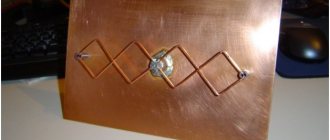
Z-type antenna
The lattice looks like 2 diamonds attached to each other so that they form a figure eight. The cable is connected to the junction of 2 diamond-shaped metal frames.
In a simplified implementation, the Z-type (bisquare) can consist of only one metal diamond. For enhanced reception, it will include capacitive inserts in the form of a horizontal figure of eight. In this case, connect the cable in the gap between the inserts.
The optimal size of the diamond side is 34 cm, and the insert size is 17 cm. For assembly, use tubes made of aluminum, copper or brass.
Route the television cable along the sides of the antenna array.
Advantages:
- easy to make from a small set of materials;
- reliability.
Flaws:
- the grating is sensitive to polarization;
- You will need a reflector mirror to reflect the waves onto the receiving resonators.
The figure-eight antenna is used by truckers to receive an amplitude or frequency-modulated signal. With its help, they communicate with colleagues on the highway and listen to FM radio stations.
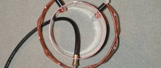
A loop
For such a receiving device you only need a television cable. Its core is metal and can receive signals in any radio frequency range. To make an antenna:
- Buy a TV cable with a copper core;
- Strip one end of the television wire to the central core.
- Remove the outer insulation at a distance of 220 mm from the exposed end of the wire. The shielding layer must remain.
- Step back another 220 mm and remove the insulation with the shielding layer up to the central core.
- Connect the central cores at the end of the wire and at a distance of 440 mm from it to form a ring.
- Expose the opposite edge of the wire and install the connector on it to connect to the TV.
It will take 5-10 minutes to make an antenna, but it will not receive a signal in difficult operating conditions. If you like the idea, but the transmitter is far away, try making several loops. Place them at a distance of 10-15 cm from each other.
Log-periodic antenna (LPA)
One of the most effective antenna designs is log-periodic. They are free from the disadvantages of a number of configurations, offer a uniform amplitude-frequency response and high gain without the use of amplifying devices.
The LPA operates in a wide range of radio frequencies, but this slightly weakens the receiving qualities of the antenna. Losses during signal transmission from the grid to the cable are minimal.
When designing an antenna, keep in mind that:
- the lengths of the resonators depend on each other logarithmically;
- the distance between the resonators depends on the operating frequencies;
- The size and distance of the vibrators does not change linearly, but in geometric progression.
To attach the resonators, 2 main central rods of the collecting line are used. They run parallel one above the other with a small gap.
Log-periodic antennas come in 3 types:
- Delta, in which the vibrators form a single circuit. They are arranged in a zigzag pattern along the center line from one piece of wire.
- Wave channel – along the central stubbles, resonators of the same length are located at different distances.
- Symmetrical. Available in single and double designs with symmetrical arrangement of vibrators.
To build your own LPA for decimeter radio waves, use the following characteristics:
- KU – 8 dB;
- number of vibrators – 11;
- The size of the resonators and the gap between them must correspond to the table below.
Characteristics of resonators for LPA
| Characteristic | Parameter |
| Length of resonators, cm | 15,95; 14,35; 12,92; 11,62; 10,46; 9,42; 8,47; 7,63; 6,86; 6,18; 5,56 |
| Distance between resonators, cm | 10,84; 9,76; 8,78; 7,9; 7,11; 6,4; 5,76; 5,19; 4,67; 4,2 |
| Jumper size to the last element, cm | 76,8 |
| Distance from the first resonator to the jumper, cm | 8 |
| Input resistance, Ohm | 75 |
| Advantages | Flaws |
| Wide reception range | Assembly complexity |
| Increased ratio enhanced | It is difficult to calculate the dimensions of the antenna resonators and reflectors yourself |
| Receives Wi-Fi, Bluetooth and cellular signal |
How to make a LPA with your own hands, see the video for more details.
Wave channel antenna
The wave channel is distinguished by the same size of vibrators. Signal reception at different frequencies is possible by changing the distances between the resonators.
Wave channel (VC) is a type of antenna used for long-distance reception. Several types of antenna arrays fit under the concept of VC.
The more vibrators on the VK body, the more CU. To work with DVB-T2, an option with a resistance of about 300 Ohms is suitable. We recommend using VC in conjunction with amplifying devices or symmetrizers.
If you decide to assemble a wave channel, do not use old Soviet designs. They are unsuitable for working with modern multiplexes.
The easiest option to assemble consists of a dozen galvanized rods, each of which is 1.5 cm wide and up to 0.1 cm thick.
Characteristics for the wave channel
| Characteristic | Parameter |
| Back strap size, cm | 34,94 |
| Second bar size, cm | 27 |
| Length of 1 resonator, cm | 19,71 |
| Length of 2 resonators, cm | 18,46 |
| Length 3-10 resonators, cm | 16,74 |
| Distance between resonators, cm | 2,78; 9,14; 18,03; 26,93; 40,89; 53; 61,93; 74,8; 92,42; 10,518 |
| Input resistance, Ohm | 300 |
The antenna gain increases from 8 dB to 15 dB with increasing frequency of signal reception.
For another example of a homemade VC with reception at a distance of up to 30 km, see the video.
All-wave antenna
It differs from a conventional antenna in that it receives meter and decimeter waves. The easiest way is to make it from two different-range subsystems.
The easiest way to make an all-wave antenna (VA) at home is:
- from beer cans;
- in the form of two petals;
- butterfly
Lobe antenna
In the petal configuration, copper wire is stretched from the center to two crossbars. The result is 2 triangular receiving petals.
The distance between the pieces of wire is up to 2-3 cm at the ends and up to 1 cm at the base of the antenna.
Butterfly
The receiving antenna can be made with a butterfly. To do this, position the resonators as in the photo below. A piece of plywood 55.8 by 6.3 cm is enough.
Place the holes for mounting the vibrators at the distances shown in the figure below.
The vibrators will be copper wire:
- Cut 8 pieces of 375mm each. Strip 2 cm of cable in the center of each piece. Curve the products in the center of the cleaned areas.
- Cut 2 pieces of 220 mm each. Mark each third of the wire. Clean the insulation in the marked areas and bend each stripped area in the center.
As a result, the arm of each resonator will be 18 cm long. The distance between the shoulders is 75 mm.
How to make your own indoor or external device with a 30-channel amplifier?
In general, as is already becoming obvious, creating an antenna manually is not as tricky as it might seem at first glance. Even if you plan to make an antenna with an amplifier, this also does not complicate the design much, because this unit is a compact module that just needs to be connected (soldered) correctly. However, we will try to cover the entire process of creating your own antenna for a TV to receive a digital signal in the DVB-T2 format in order.
Rules and principle of calculation
Many approach the process scientifically: they calculate the wavelength and, based on this information, determine the dimensions of the antenna. In fact, this is in many ways an unnecessary complication.
- If you are planning to build an indoor “figure eight”, then you should divide the signal wavelength by 4. You will get the length of each edge of the diamond of your proposed antenna. You can look for the original values in a reference book, or you can take a ready-made number - 14 cm (antenna edge length).
- Further, in order for these two diamonds to overlap each other properly, their inner edges must be shorter than their outer ones. “With a run-up” of 14 cm, this means that the internal ribs should be 1 cm shorter (their length should be 13 cm). The antenna should be as broadband as possible (to receive as many emitted signals as possible) - stretch it wide.
- Despite the fact that the antenna looks like 2 diamonds in contact, these two elements, of course, should not be in contact with each other. At the point of greatest convergence (1-2 cm), they must bend and diverge. In addition, the ends of the wire or strip from which the antenna is formed are left longer and soldered together. In the future, the end of the coaxial cable will be soldered to them.
Location and connection
Such an antenna can be located both outdoors and inside the house, being attached to some stationary object on the window or even to a “not very stationary” object (for example, to a curtain). In the latter case, it will be extremely important to correctly orient the antenna towards the signal emitter. It’s also impossible to go wrong with the connection – the TV only has one socket for a coaxial cable.
As mentioned above, simple DSM antennas or multiwavelength antennas may be suitable for receiving digital television. In this case, the connectors of their plugs just need to be connected to the standard sockets on the TV.
Main settings
A decimeter antenna is characterized primarily by its radiation pattern. The main parameters of this characteristic are the level of the side (auxiliary) lobes and the width of the main lobe. The width of the diagram is determined in the horizontal and vertical planes at a level of 0.707 from the largest value. So, according to this parameter (the width of the main lobe), diagrams are usually divided into non-directional and directional. What does this mean? If the main lobe has a narrow shape, then the antenna (decimeter) is directional. The next important parameter is noise immunity. This characteristic primarily depends on the level of the back and side lobes of the diagram. It is determined by the ratio of the power released by the antenna, subject to a consistent load at the time of receiving a signal from the main direction, to the power (with the same load) when receiving from the side and rear directions. First of all, the shape of the diagram depends on the number of directors and the design of the antenna.
Homemade frame “eight” for long-distance reception of “digital” signal
So, the preparation and sequence of actions when forming a “figure eight” or diamond-shaped antenna for receiving a digital TV signal.
Assembly materials
- Cable. The coaxial connecting cable must have at least one stripped end (solid core) for soldering to the antenna circuit.
Stripping here should be carried out to a length of at least 2 cm. The internal structure of the cable should be separated from the insulation: the monocore should be left without insulation and braiding. As for the insulation, it is generally better to cut it off, but the braiding (and foil) needs to be twisted into a single bundle. Next, we tin the monocore separately and the braid separately. Each of the resulting tinned conductor outputs (at one end of the cable) must be soldered to its own end of the plug. Now we connect it to the TV. After this, the soldering area should be insulated and the gripper should be pressed around the resulting insulation. - Wire for antenna circuit. It should be calculated and processed as follows:...
Calculation
A rhombus is a geometric figure in which all sides are equal. A little higher, the size of such a rib was taken to be 14 cm. There is no need to maintain exceptional accuracy here - just about.
- The first section is internal. We take it equal to 13 cm, plus 1 cm for the soldering loop.
- Next are 2 sections of 14 cm each.
- Then again 2 internal sections of 13 cm each, between which there is a “turn” of the wire in the opposite direction.
- Then again 2 outer sections of 14 cm each.
- And the last finishing section is 13 cm, plus 1 cm for the loop.
A total of approximately 112 cm. The loop (that is, the place where the ends of the antenna circuit are soldered) should be located, as it were, on the “bridge of the antenna”. If everything is measured correctly, then there will be a distance of 1-2 cm between the ends of the diamonds.
How to assemble - description, diagrams
- After the circuit has been made and the antenna coaxial cable has been prepared, they should be connected together.
The place of soldering is not accidental - it should be located exactly at the point of connection of the ends of the antenna circuit.The receiving ability of the antenna and its reception range depend on this.
- Next, fill the joints with sealant. It is also recommended to wrap all places where soldering was carried out with electrical tape as a final layer.
The drawing of this indoor antenna is shown below:
Connecting to a TV
Connection is inextricably linked with testing the finished antenna. Turn on the TV, connect the antenna and try to find a place where the broadcast reception is better. If no improvement is noticed from moving and rotating the antenna, then do not rush to despair - perhaps the problem is a substandard coaxial cable.
Unfortunately, there is only one way to find out if this is true - replace the used cable with an alternative one (for example, a “telephone noodle”). If the antenna signal becomes better after this, then the cable is indeed to blame. However, you won’t be able to stay on the auxiliary cable for a long time - it tends to quickly fail. You will need to get a new section of coaxial cable.
Butterfly shaped
Another version of an all-wave antenna, which allows you to receive a fairly large number of channels in good quality. Due to this, its work can replace the use of satellite dishes, but the manufacturing process also requires extreme attention, accuracy and time. Structurally, it will consist of a wooden board and several pieces of copper wire with a 4mm core, bent in the shape of butterfly wings, which is where the name of the model comes from. Initially, you need to mark the location of the holes on the board and drill them according to the diagram:
Rice. 11: Butterfly antenna hole pattern
Next you need:
- Cut 8 identical pieces of wire, 37.5 cm each, 2 pieces for connecting the “wings”, 22 cm each, and 2 pieces for connecting to the socket;
- To create electrical contact on the sections, strip the insulation as shown in the figure.
Rice. 12: strip the insulation on the wires - Bend the pieces of wire along the exposed areas, V-shaped should be obtained with equal sides and a distance of 7.5 cm between the ends.
- Install all the wire elements on a wooden board, as shown in the figure, and secure with self-tapping screws.
Figure 13: Install wire elements on the board - Connect the leads from the receiver to the socket, and connect the cable for signal transmission there.
Rice. 14: connect the leads to the socket
The broadband antenna is ready for use; you can install it in the most suitable place in the room for receiving television signals.
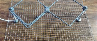
Double or triple square for 100 km
This design is an alternative version of a homemade indoor antenna, with which you can quite effectively amplify even a weak signal clogged with external interference. The antenna is actually made up of two, three or more squares formed from a conductor (copper or brass wire) and mounted on two bars (made from the same conductor).
Its main feature is that such an antenna needs precise positioning: it must look exactly at the transmitter, otherwise the effect of amplifying a weak signal cannot be achieved. Such an antenna is suitable for receiving a signal at a distance of 100 km.
Construction and materials
Square frames are smaller the further they are from the holder.
The location of each subsequent square relative to the previous one is 50% of the length of the side of the square.
- The largest one is the reflector.
- The smaller square is called the vibrator.
- The smallest (third) square is the director.
- The planks that hold the squares together are called arrows.
3 squares provide the most powerful gain (the main thing here is to accurately point the antenna at the emitter). Such an antenna should be mounted on a wooden holder, and any metal parts and parts should be removed from the frames at a distance of at least one and a half meters.
Connecting the active frame (vibrator)
Connecting the antenna frames to the coaxial cable must be done using a matching device. As the latter, a balancing short-circuited loop is used. It is made from sections of antenna cable and has 2 sections: the right one is the “loop” and the left one is the “feeder”. The task of the loop and feeder is to act as an adapter from the volumetric circuit of the antenna to the asymmetric coaxial cable. To connect from the ends of both the cable and the feeder at a distance of 20-25 cm, the insulation is removed and the aluminum screen is removed, and the cable braid is twisted into a bundle. Then:
- The braid of the cable and the core of the feeder cable are soldered to the left end of the vibrator (which is cut at this point, forming a square half-ring).
- The feeder braid is soldered to the right end of the vibrator.
- The cable braid (from the other end) is also connected to the feeder braid using a metal jumper. The bundles connected in this way should be soldered together.
- The cable cores must be parallel to each other. The distance between them should be no more than 5 cm. In order to guarantee such a mutual arrangement, you should use, for example, a textolite plate as a mounting base.
- The coaxial cable to the TV is connected (soldered) to the bottom of the feeder. That is, it turns out that the braid is soldered to the braid, and the central conductor is soldered to the central conductor.
Such an adapter will add clarity to the image and eliminate interference, especially at large distances where the antenna is located from the transmitter.
The drawing with dimensions is shown below:
Types of TV antennas
A television antenna is a device specifically designed for receiving broadcast television signals that are transmitted at frequencies from 41 to 250 MHz in the VHF range, and from 470 to 960 MHz in the UHF group.
There are two types of television antennas:
- Internal – located on top or next to the TV;
- External - installed on the roof or attic of the house.
Outdoor antennas are more complex to manufacture and install, but such devices are necessary for adequate reception in peripheral areas remote from television stations.
Antenna devices are also divided into:
- Active, which are complemented by an amplifier and require connection to an electrical power source;
- Passive, which amplify the signal only due to design features.
An outdoor TV antenna is a high input power device and has a unidirectional radiation intensity so its far end must always face the broadcast station.
Based on the wavelength that television antennas are capable of receiving, they are divided into three groups:
- MV antennas - such devices receive very long meter waves, the size of which can be from 0.5 to 1.5 m;
- UHF antennas - these devices operate in the decimeter range, in which the wavelength is in the range from 15 to 40 cm. It is in this coverage that digital television (DTV) is supplied;
- Broadband antennas are a hybrid design in which both VHF and UHF elements are installed. Such radio installations are used to receive digital and analogue broadcasts simultaneously.
The most commonly used design is an outdoor television antenna based on a log-periodic dipole matrix. Such products consist of several half-wave elements consisting of metal rods. They act as resonators in which energy is stored by radio waves, which cause electrons to move and create stable waves of oscillatory voltage. An antenna can have a different number of rod elements: the more, the higher its gain.
Another popular design, used primarily for UHF reception, is the reflective TV antenna. Such a device consists of a vertical metal screen with several dipole elements installed in front of it.
The television broadcast bands that must be covered by a single antenna are too wide in frequency, so either separate antennas or combined devices are used for the VHF and UHF bands. In such designs there are two types of elements: long elements that pick up the MF (these are located at the rear of the antenna boom and often function as a log-periodic antenna) and short elements that pick up the UHF broadcast (these are located at the front of the boom).
When you listen to the radio, you notice that local channels can be easily tuned in the FM or VHF range, but you won’t be able to catch distant foreign broadcasts on them; to do this, the receiver needs to be switched to MF and HF mode.
This suggests that meter, medium and short waves are well transmitted over long distances, while ultrashort and decimeter signals have a small coverage area. However, the disadvantage of the UHF range in which our digital television operates is minimized thanks to two things:
- Firstly, the presence of a large number of towers;
- Secondly, the ability of large objects to reflect the signal.
If you live in a private house next to a high-rise building, then it is more correct to point the TV antenna not at a distant tower, but at a neighboring house, which perfectly reflects the waves. The correct choice of direction largely determines the quality of the TV signal.
"Wave Channel" (up to 50 km)
A wave television antenna is also effective, although only for picking up a television signal at a distance of up to 50 km. You can also build it yourself.
Dimensions and diagram
Single-channel antennas of the “wave channel” type are directional antennas that effectively amplify a weak television signal (including digital).
In fact, this is a set of many single-channel antennas united by a single boom. To connect to a single coaxial cable, a similarly designed balun adapter is also used here.
Each antenna in this complex provides signal reception via one channel. As a result, this improves the quality of reception and visual image. Wave antennas are also effective in cases where the broadcast signal comes from several directions (if, for example, there are several transmitter emitters near the receiver). Such antennas do not need to be clearly oriented towards the signal source, which makes them very ergonomic to use.
“Wave channel” antenna elements are best made from:
- The supporting boom is made of aluminum or copper (which is less common) tubes, 2-4 cm in diameter - on channels from the first to fifth, from tubes with a diameter of 20-30 mm - on channels from six to twelfth.
- Vibrators (parts transverse to the load-bearing boom) are also made of metal tubes with a diameter of 16-22 mm - on channels from the first to the fifth; and with a diameter of 10-14 mm - on channels from the sixth to the twelfth.
Attachment to the mast is carried out at the center of gravity of the antenna boom.
The drawing is shown below:
How to make and connect it yourself?
Manufacturing is carried out by squeezing and then welding tubes of the specified diameters together, namely:
- first the supporting boom is formed;
- then transverse vibrator antennas are welded onto it.
The antenna is connected to the TV using a coaxial cable through a balun adapter.
Types of decimeter antennas
The UHF range may be the only one recommended or one of the possible ones for an antenna array.
UHF receiving antennas are classified according to the presence of an amplifier:
- Active - grilles with a built-in amplifying device. They are suitable for reception over 30 km. Active models require power supply; it is supplied from the mains or via a television cable.
- Passive - ordinary grilles with a set of vibrators. For example, an LPA without an amplifier receives radio waves at a distance of 30 km. Connect an additional amplifier to the passive receiving array if the radio transmitter power is not enough.
UHF antennas are divided into indoor and outdoor. The latter are large in size and have an unaesthetic appearance; they are attached to walls or masts.
Indoor UHF antennas are mounted on walls or placed on horizontal planes. We recommend installing them in urban areas or in villages, if the FSUE RTRS tower is in direct visibility from the reception location.
All-wave indoor antenna MV-UHF
The MV-UHF television receiving antenna operates in the radio frequency range from 30 MHz to 3 GHz, which corresponds to a wavelength from 10 cm to 10 m.
These radio frequencies broadcast:
- Analog radios;
- Analog TV channels;
- Digital TV channels.
All indicators for such antennas are the same, but there are several individual disadvantages:
- The wider the overall range of the antenna, the worse the reception performance for a particular frequency.
- A wideband antenna is easier to overload because it can pick up more radio junk. If overloaded, the receiver will be temporarily inoperable.
UHF indoor antenna
Suitable for receiving analogue or digital TV channels in its frequency range. The analog signal is gradually disappearing from Russia due to the state digitalization program. Permissions for non-digital TV channels are not issued, and old ones stop working ahead of schedule. Therefore, universal antenna arrays are gradually losing their relevance, leaving only decimeter ones.
Modern Russian radio stations continue to transmit analogue, but they do not operate on the reception frequencies of UHF antennas.
With a decimeter grille, you will get reception quality and overload protection higher than with universal offerings.
How to assemble a “butterfly” using bolts and without a soldering iron?
It consists of a supporting rod (which can be made of wood) and a series of vertical antennae, and therefore looks like “whip” factory digital television antennas. The difference is the absence of a phased array, instead of which a frame is used.
The concept is:
- Pin antennae made of aluminum wire, 5-6 mm in diameter, are fixed to bolts placed in the array of the supporting rod (usually by twisting around them in 1 turn).
- And then these pin antennae are connected to each other by the same aluminum cable, which plays the role of a vibrator. To connect to a coaxial cable, a balun adapter is also required.
This antenna is the best option for making at home from scrap materials, because it provides high-quality reception at a distance of up to 60 km.
In addition, noise removal and image stabilization are relatively good.
See the drawing below:
Calculation
Depending on the design, you can make an all-wave antenna yourself or one that operates in a specific frequency range. There is one fundamental difference between them - all-wave devices are not capable of receiving a weak signal, especially one drowned out by the background of stronger radiation. Other homemade antennas do not cover all digital broadcast frequencies.
In order to correctly make a working antenna for digital TV, its calculation must be approached responsibly for one more reason - in practice it is impossible to check the quality of digital signal reception.
If, at a low signal level, analog television works with interference, but shows, then there is no image in digital and it is not clear whether the problem is in the device or in another (cable, weak reception signal). In this case, development work with the antenna already turned on will not work.
Modern Smart TVs and receivers display the level of the signal recorded at the receiver, but most conventional digital devices do not support this function. It is impossible to make even a simple decimeter antenna yourself without calculations, unless it is all-wave.
Calculation rules
Digital TV broadcasts from different multiplexes at different frequencies, which correspond to different wavelengths. To receive a high-quality signal, the emitted wave must completely “lie” on the active area of the receiver.
Therefore, calculating an antenna for digital television with your own hands must be done according to the following scheme:
- calculate the DVB-T2 wavelength for the antenna emitted during broadcasting of each multiplex;
- select the longest wave;
- calculate the half-length of the wave cross section, because it is projected perpendicularly onto the receiver.
Below we will consider the procedure for calculating the active area for a digital antenna with your own hands, and as an example we will take the calculation of the broadcast frequency in Moscow.
Case Study
Today in Moscow there are three packages of terrestrial DTV channels:
- 1st multiplex (32 TVC, 546 MHz);
- 2nd multiplex (24 TVC, 498 MHz);
- 3rd multiplex (34 TVC, 578 MHz).
The wavelength is calculated using the formula ƛ = 300/F, where F is the frequency in megahertz (MHz). As a result, each multiplex sends a wave:
- ƛ1 = 300/546 = 0.55 m;
- ƛ2 = 300/498 = 0.60 m;
- ƛ3 = 300/578 = 0.52 m.
It turns out that the repeaters of the second multiplex of Moscow television emit a wave of the greatest length, which will later be used for calculations.
Important! For ease of calculation, the resulting value can be rounded, but only up!
The only thing left to do is to calculate the length of the active region of the future receiver, which will receive the signal. Because the emitted wave has a sinusoidal shape, then its cross section will be ½ the length, and the half-length - ¼. The total is 0.60/4 = 0.15 m = 15 cm for digital television.
Advice! The calculation is shown for all multiplexes as an example, but it can be simplified by calculating the value for only one channel package. Radiation of a lower frequency will always have the longest electromagnetic wavelength.
The simplest one for a summer residence is made from beer cans and copper wire
The simplest homemade TV antenna for a TV at home is done like this. You will need 2 aluminum or tin cans and a piece of wooden plank or plastic pipe. You can use aluminum beer cans , as long as their walls are smooth (not ribbed).
- The jars need to be washed and dried.
- The coaxial wire is cut: the braided strands are twisted separately, and the central core is left separately.
- We get two conductors - we attach them to the cans: we take two small self-tapping screws with flat heads, twist a loop at the ends of the conductors, thread a self-tapping screw with a washer installed on it into it and screw it to the can.
- The metal of the can must be cleaned in advance by removing the deposits with sandpaper.
- We fix the cans on the bar. We select the distance between them individually - we focus on the quality of reception.
Such an antenna will naturally not be powerful. In normal quality there will be one or two channels (this is at best). Much will depend on the position of the repeater, the “purity” of the radio wave corridor, how correctly the antenna is oriented, etc.
Here is a drawing of such a TV antenna:
From the video you will learn how to make an antenna from beer cans:
Location and connection
When the theoretical calculations have been made, all that remains is to plan the future structure for assembly with your own hands.
There are two planning issues to consider:
- location
- connection.
These factors are interconnected and conflict with each other:
- You can make a home or outdoor antenna with your own hands.
The latter can be a simple unidirectional television receiver, which is not interfered with by signal-attenuating obstacles (house walls, other buildings). Also, an outdoor digital antenna can be installed on the roof, which will significantly improve the quality of the received signal. It should be directed to a digital television repeater. - For installation outdoors, and especially on the roof, a long cable is required. It causes natural signal scattering (noise) and the longer its length, the weaker the signal level reaches the TV.
To make an antenna for digital television with your own hands that will work effectively, you will need to find a compromise between these factors.
In densely built areas or sparsely populated areas with a large distance from the television repeater, the digital antenna will have to be taken outside. In other cases, an indoor receiver also works effectively.
Advice! There is no clear rule for choosing a placement; each case is unique. The best indicator of a reliable installation is neighboring houses. If there are a lot of outdoor devices for receiving television, then make one. In an area of super-dense buildings, you need to look at the roofs of multi-storey buildings.
A small number of receivers does not indicate anything (sometimes, for greater confidence, residents install them even in conditions of good reception by room devices). Only if there are many antennas, and among them there are collective ones, installation on the roof will be required.
Which indoor antenna is better to buy for your home?
Having analyzed all the advantages and performance characteristics of the listed indoor TV receivers, our editors chose the REMO Digital device as a leader: one of the most reliable and high-quality receivers, the operation of which is possible not only in conditions of maximum proximity to the TV tower, but also at a considerable distance from her. It is plastic windows that can interfere with the reception of a high-quality signal, since they are a barrier to the penetration of radio waves. The equipment operates on a simple principle and facilitates the search for new channels in digital format. You can learn about the technical parameters of the declared model from the previous section. A common-mode antenna can be created independently and can become an amplifier for an indoor antenna.