What is digital television
Now almost all users are switching to digital television. This is due to the fact that it has a built-in system, thanks to which the signal is transmitted without any interference. Moreover, it is thanks to digital television that audio and video signals are transmitted in the highest quality. Also, the main advantage of this type of television is that the user can independently configure the television channels necessary for him. They can be federal or entertainment, sports or musical, and so on.
It should be noted that the digital type of television signal broadcasting has a considerable number of advantages in comparison with analog television. Namely:
- It is possible to broadcast a television signal even using transmitters that do not have high power;
- The digital signal is more resistant to various interferences that may arise during operation;
- The image is transmitted in maximum quality, and the sound without any interference;
- A user who has switched to digital television will have access to a fairly wide selection of television channels;
- After switching to digital television, the subscriber will be able to use various interactive systems built into the television;
- Digital television allows you to turn on subtitles, rewind, and pause while watching a program;
- The user can archive the necessary transmissions.
It is important to understand that these are not all the advantages of the presented type of broadcasting, since it also has various broadcasting formats, which also have their own characteristics.
Features of digital signal transmission over communication lines
In the process of functioning of digital television and radio complexes, the need periodically arises to transmit digital signals via communication lines, for example cable, between individual control rooms and studios. Digital signals can be transmitted over longer distances - between individual buildings of the complexes.
possible ways to transmit bits of binary numbers corresponding to PCM signal samples. If each sample bit is transmitted on a separate line, then this is parallel transmission. The clock signal in this case will also be transmitted over a separate connecting line. The need for a large number of cable lines is a serious disadvantage of parallel transmission, especially for delivering signals over long distances. Special multi-pair cables and complex connectors are required. This method is practically used only for connections within the equipment and to a lesser extent in the case of intra-studio connections.
To transmit signals between hardware rooms and over longer distances, more economical serial transmission is used, when all sample bits are transmitted over one physical line using the time multiplexing . At the same time, the clock frequency and attenuation in the cable increase significantly. The transition from parallel to serial transmission and back is carried out using appropriate converters, called in engineering practice parallel-serial and series-parallel converters.
When transmitting over a real line with noise and interference, the rectangular shape of the pulses at reception is distorted, the fronts are stretched and, as it were, blurred by noise. When passing through the receiving switch, the point of compliance with the threshold level may shift chaotically due to the influence of noise, and phase jitter occurs, leading, as in the presence of a constant component, to inaccurate restoration of the clock frequency. With long cables and significant jitter, the transition can shift into the region of the adjacent clock interval - intersymbol interference occurs. [1, p. 51]
One reliable way to achieve synchronism is to use a narrowband phase-locked loop (PLL) . In this circuit, the source of the clock signal is a highly stable oscillator, frequency-controlled by the voltage from the output of the phase detector, which compares the frequency and phase of the generated oscillation and the clock signal, and reliable synchronization is ensured. [1, p. 51]
Features of transmitting high-frequency signals via coaxial cable
Comparative frequency response of the cable line, equalizer and frequency response of the output signal after the equalizer. Cable and EQ Gains
Modern television coaxial cable has an internal copper-plated steel conductor, an internal polyethylene foam dielectric, and shielding with foil and steel braiding. Some cables have two layers of foil, between which there is a steel braid.
The standard 75-ohm coaxial cable for digital signal transmission is Belden Inc.'s 1694A It is distinguished by a low level of signal loss at high frequencies. Signal attenuation at 3 GHz is 10.67 dB/100 ft .
Depending on the length of the cable, different signal attenuation occurs, which is determined by the level of absorption in the dielectric, the level of radiation, load capacitance and skin effect.
The main factor limiting the transmission of high-speed signals in coaxial cable is the skin effect - attenuation is directly proportional to the signal frequency. The frequency dependence of signal attenuation in a cable is the cause of waveform distortion and intersymbol interference.
Therefore, in order to completely restore the signal shape, it is necessary to compensate for all losses due to various effects. This function is provided by a cable receiver - equalizer . The equalizer uses an amplifier frequency response is inversely related to the signal attenuation in the cable. Special filters in the equalizer structure provide measurement of two components of the degree of attenuation and synthesis of a control signal for an amplifier with frequency-dependent and controlled gain.
Digital television formats
The digital television broadcasting system was developed in 1993 and is abbreviated as “DVB”. After this, an international organization created standards that were developed to ensure full compatibility of various equipment with information sending technologies.
The developed standards also differ in abbreviations based on continental characteristics. Namely:
- In Europe, a standard called "DVB" is used;
- In Asia, a standard called "ISDB" is used;
- In South and North America a format called "ATSC" is used.
Cities in Russia and other post-Soviet countries also use the European digital television transmission standard. In addition, all of the above standards are also divided into formats that determine the features of broadcasting a television signal.
As noted above, in digital television the user is provided with a fairly wide range of various additional options. For example, channels on a TV can be broadcast in HD quality, an ongoing broadcast can be paused or rewinded, and the image can also be recorded and archived. However, the provider may provide such services by charging additional fees for their use. Federal television channels are divided into groups of multiplexes. On average there are about 30, but this completely depends on the region in which the broadcast is taking place.
The user can set up federal channels absolutely free.
In addition, the European television broadcast standard is also divided into four formats:
- Mobile television type DVB-H (SH);
- Terrestrial television type DVB-T (T2);
- Cable television type DVB-T (T2);
- Satellite television type DVB-S (S2).
It should be noted that the abbreviations placed in brackets indicate that the second generation of the presented standard has now appeared.
Digital interfaces for transmitting video and audio data
A digital interface or junction is the point where two digital devices connect , at which data is transferred from one device to another. To ensure a fast and reliable connection without adjusting parameters, both devices must meet the same requirements at the junction point. In interfaces, more than in any other area of digital technology, standardization is important.
The connection can be unidirectional, or simplex, when data is transferred in one direction, and bidirectional, or duplex , when data is transferred in both directions. Half-duplex operation is also possible, when data is transmitted in both directions, but not simultaneously, but separated in time. Naturally, real-time signals, for example, in television or sound broadcasting systems, can only be transmitted in simplex mode.
Before getting acquainted with the parallel and serial interface, let's consider the principle of converting an RGB (for example, from a television camera) into a parallel and then serial data stream.
Digitizing RGB video signal in a digital camera
• The gamma-corrected RGB is converted by a linear matrix into a luminance component and two scaled chrominance components P'b and P'r .
• Y' is transmitted over a wider frequency band ( 5.5 MHz ).
• Luminance and chrominance signals pass through low-pass filters , which suppress high-frequency components of the video signal, which can cause distortion during the signal sampling process.
• The filtered luminance signal is digitized at a frequency of 13.5 MHz using an ADC , the output of which is a 10-bit data stream with a width of 13.5 Mbit/s .
• Color signals are digitized at a frequency of 6.75 Mbit/s, each with its own ADC , the output of which generates two data streams with a width of 13.5 Mbit/s .
• Three video channels are multiplexed into a single 10-bit, 27 Mbps .
Processing and converting parallel data stream into serial
The coprocessor is used to add clock references, AES/EBU , and other overhead.
A 10-bit, 27 Mbps wide parallel data stream is loaded into a shift register (or parallel-to-serial converter), where it is clocked at 270 MHz and encrypted for transmission compatible, in this example, with the ITI-R standard definition format. BT-656/SMPTE 259M.
Digital television data is transmitted between different types of studio equipment in both parallel and serial code. Despite the fact that the BT-656 standard regulates transmission in parallel code over distances of up to 50 m , this interface is usually used for intra-block communications over distances of no more than a few meters.
Serial code transmission is preferred when transmitting video signals over distances up to 400 m .
Television studio equipment can be located in different rooms and on different floors of the building, as well as in different buildings. The length of cable connections between different pieces of equipment can reach several hundred meters.
Parallel video interface
The parallel interface for the 4:2:2 provides simultaneous transmission of binary information over a connecting line separate for each bit, that is, the number of lines is 10 for a 10-bit codeword . However, each line needs to transmit data about the value of the bits of the three component signals, for which time multiplexing is used (Fig. 2.8).
Rice. 2.8. Parallel interface signal generation
The digital composite signal of the PAL and NTSC . In this case, multiplexing is not required, and the code words follow the communication lines with the frequency of the fourth harmonic of the subcarrier 4fsc : for the PAL system - 17.7 MHz , for NTSC - 14.3 MHz .
The parallel interface for the 4:2:2 offers simultaneous transmission of binary codeword symbols in BVN over separate connecting lines, the number of which is 10 (codeword length) (Fig. 2.8). Since three component signals must be transmitted digitally over 10 lines , the interface uses time multiplexing, or multiplexing. Video data words are transmitted in the following order: [Cb, Y, Cr], [Y], [Cb, Y, Cr], [Y] , ....
Here, the three words [Cb, Y, Cr] describe the three combined components of one image element, and the word [Y] refers to one luminance component of the image. This is due to the fact that the sampling frequency of the luminance signal is 2 times higher than the sampling frequency of color difference signals . Words follow at a frequency of 27 MHz (with a period of 37 ns) .
The beginning of the active part of the digital line is preceded by a synchronization reference signal SAV (Start of Active Video) of 4 words , and after the end of the active part of the line there follows a reference signal EAV (End of Active Video), the duration of which is also 4 words .
SAV and EAV signals are words corresponding to the numbers 0 and 1023, which cannot be used when encoding video data. 1440 words must be transmitted ( 720 words for the luminance signal Y and 360 each for Cr and Cb ), and the total number of cycles in the line is 1728 625/60 system and 1716 for the 525/60.
Transmitting data in parallel form according to the 4:4:4:4 requires multiplexing of four signals: three components of the video signal and the A-signal . The word frequency is 54 MHz (period - 18.5 ns ), 2880 words (with a total number of clock cycles in the line of 3456 for the 625/50 ).
A digital composite signal can also be transmitted in parallel form (Fig. 2.8.1). Multiplexing is not required in this case, so the codewords follow the communication lines at the fourth harmonic frequency of the color subcarrier 4fsc . The reference time signal for the digital stream is a TRS (Timing Reference Signal) package of 3 words , formed from the numbers 0 and 1023 .
TRS signal follows the edge of the analog row clock. PAL signal stream, the duration of the digital line is not equal to the duration of the analog line, so the position of the TRS relative to the analog line clock gradually shifts. Once per field, the temporal position of the TRS by changing the number of samples in the last lines of the fields. Following the TRS , an ID line number identification signal is transmitted on the digital line within a sequence of 4 (for the NTSC system) or 8 (for the PAL system) fields.
Rice. 2.8.1. Digital composite signal
The parallel interface requires the transmission of binary bits of code words using symmetrical two-wire lines (Fig. 2.8.1.). Signal transmitters and receivers are compatible with emitter-coupled logic ICs . It is important to note that in addition to the 10 bit lines of codewords, another similar line is used along which the clock pulses are transmitted . Without clock pulses, digital signals in the BVN cannot be correctly decoded at the receiving end.
Component 4:2:2 and composite 4fsc parallel digital interfaces allow data transmission over a distance of up to 50 meters without the use of frequency correctors. For a 4:4:4:4 , the same distance is 25 meters . With the help of frequency correctors, the transmission distance can be increased, however, with large lengths of connecting lines, errors are possible due to the temporary divergence of signals from different lines.
So, to summarize, we can say:
• The maximum length of lines should not exceed 50 m , but in practice is limited to 30 m .
• Using frequency correctors, the transmission distance can be increased, but with long connecting lines, errors may occur due to the time divergence of signals from different lines.
For relatively short distances between connected devices, a parallel interface has long been the most practical option for transmitting video data. However, the parallel form is inconvenient if digital signals need to be switched. Complex and bulky connectors and cables also create inconveniences. [1, p. 59]
Serial video interfaces SDI, SDTI and FC
In order to create a single interconnected communication environment, the EBU/SMPTE Working Group on harmonized standards for the exchange of program material in the form of digital streams from a large number of existing and planned interfaces and networks that form all kinds of transport systems, identified five: IP (Internet Protocol), ATM (Asynchronous Transfer Mode), SDI/SDTI (Serial Digital Interface/Serial Digital Transport Interface), FC (Fiber Channel) and IEEE-1394 . If the first two interfaces are applicable for both local and global communications, then the action of the others is limited only to local networks and hardware-studio complexes for various purposes.
Various digital serial interface standards use one (or more) coaxial cable with BNC connectors with a nominal impedance of 75 ohms . The same type of cable is used for analog video, but at higher rates higher quality cables are preferred. Signal amplitude swing 800 mV (±10%) . Signal attenuation during transmission over long distances can be compensated on the receiving side, which makes it possible to transmit a stream of 270 Mbit/s over distances of up to 300 m . For HD streams, shorter distances are acceptable - usually up to 100 m .
SDI
There are several SDI standards:
• SD-SDI - for transmitting standard definition broadcast quality digital video; • ED-SDI (Enhanced Definition Serial Digital Interface) - for transmitting digital video of improved quality with progressive scan; • HD-SDI (High-Definition Serial Digital Interface) - SDI for high-definition television (HDTV) provides a data stream of 1.485 Gbit/s ; • Dual Link HD-SDI - for progressive scan HDTV, allows transmission of up to 2,970 Gbps via two physical HD-SDI connections; • 3G-SDI - for HDTV transmission with progressive scan stream up to 2.970 Gbit/s via a single coaxial cable.
The SDI digital serial interface is based on Recommendation SMPTE 259M (Serial Digital Interface for the transmission of 10-bit 4:2:2 component video signals and 4fsc digital composite video signals) and Recommendation ITU-R VT.601-5 and is designed for generation and transmission of uncompressed data .
The serial interface involves alternately transmitting the binary bits of each codeword into the communication line, which is achieved by multiplexing (Fig. 2.9).
Rice. 2.9. Formation of a serial data stream
As a result of this conversion, the clock frequency increases a number of times equal to the length of the codeword. When transmitting 10-bit codewords of the 4:2:2 standard , the digital video data rate will be 270 Mbit/s , which corresponds to a clock frequency of 27 MHz and a data change period of 3.7 ns . Data transfer rates for the main standards in the SDI stream are presented in table. 2.1.
Table 2.1 SDI stream rates for a 625 line / 50 Hz system [1, p. 61]
Transmitting such a wideband signal (hundreds of MHz), such as a serial video data stream, over a long communication line is not the only difficulty.
It is also necessary to solve the problem of data synchronization during reception, because transmitting clock pulses over a separate line does not correspond to the concept of a serial interface.
Similar questions arise in digital video recording, where video data is recorded sequentially, and recording a separate clock signal is impractical (if only because of the double consumption of the recording medium).
Therefore, clock pulses must be extracted at the receiving end from the edges of the video data signal. If this is possible, then such a video data signal is self-synchronizing. To give video data the property of self-synchronization, as well as to coordinate them with the frequency response of a communication line (or, for example, a magnetic recording-playback channel), a special type of coding is used, called channel coding - a “non-return to zero upgraded” code in combination with scrambling (Fig. 5).
Rice. 5. Channel coding [2]
The simplest code BVN (Without Return to Zero) does not have the property of self-synchronization. It has a constant component; its spectrum is dominated by low-frequency components. The modified BVNM code differs from BVN in that when transmitting single data, level differences are formed.
If you limit the number of subsequent continuously zero data, then it becomes self-synchronizing. Biphase code (Manchester code), used, for example, in channel coding of address-time information, assumes the presence of drops in each clock cycle. In addition, when transmitting “1”, an additional level difference is formed in the middle of the clock cycle. This code has the property of self-synchronizing , it is also insensitive to polarity changes. It is used as a channel code in the AES/EBU . A procedure called scrambling involves adding data to a pseudo-random sequence. The scrambler uses pseudo-random coding , which ensures an even distribution of zeros and ones for any combination of the original digital signal, thereby ensuring that the electrical signal does not shift during transmission. The transmission is carried out in the NRZI , which is insensitive to the polarity of signals. The stream transmits data with built-in synchronization.
Partial coding is an effective method that allows you to achieve a specific transmission rate of 2 bits/(s*Hz) using pulses that occupy several clock intervals. Other channel coding methods used in digital video recording include Miller-2 code and 8-14 modulation .
BVNM code as the channel code in combination with scrambling.
The serial interface requires data transmission over a single-ended line with a characteristic impedance of 75 ohms (coaxial cable and 75 ohm BNC connector type IEC 169-8). Transmitting and receiving processors are made in the form of integrated circuits (Fig. 6). They allow you to transmit video data in component 4:2:2 or composite formats over a distance of up to 300 meters . [2]
Rice. 6. Data transmission over an unbalanced line (via coaxial cable). [2]
The maximum permissible cable length depends on the transmission speed and cable parameters. When using a cable with an attenuation of 9 dB at 100 MHz per 100 m of length, the maximum length for various types of digital video signals is shown in table. 2.2.
Table 2.2 Maximum cable lengths [1, p. 61]
The structure of the digital stream is shown in Fig. 2.11. [1, p. 61]
Rice. 2.11. SDI digital stream structure
In order to synchronize the video signal between the transmitter and the receiver, the standard defines special words in the digital stream called EAV (end of active frame data) and SAV (beginning of active frame data). Of the 1728 words of a digital line for a 4:2:2 625 line/50 Hz system , the payload information containing video data and located in the digital active part of the line occupies 1440 words . The area between EAV and SAV occupies 280 words and is used to transmit auxiliary (service) data, such as digital audio in AES/EBU , time code and others.
Thus, the share of additional data in the total digital stream of SDI can be significant - about 20% 4:2:2 component video signals and about 7% for a 4fSC . The packet, in addition to the data array, contains a header indicating the data type, the block number for sequential transmission of additional data in the block, as well as a checksum of the packet part to check the correctness of the data upon reception. Additional data is multiplexed with the video data stream by the transmitter processor and allocated at the receiving end. The SMPTE 272 M standard , Formatting AES/EBU Audio and Ancillary Data for Transmission in the Supplemental Video Data Stream, describes the placement of additional digital information in the SDI . The operating modes provided for by the standard are shown in table. 2.3.
Table 2.3 Modes for transmitting auxiliary data in the SDI stream [1, p. 63]
In studio hardware , the sampling rates of video and audio signals are usually synchronized (with an audio sampling frequency of 48 kHz), but the SDI allows you to work with asynchronous audio.
For editing rooms and other small systems, the option of a separate digital audio path is preferable to combining with video data, since video and audio processing is carried out on separate devices. However, when connecting remote hardware rooms or when switching a large number of channels, such a combination is justified when there is a great danger of “losing” the sound during switching or disrupting its synchronization with the video signal. [1, p. 63]
SDTI
the MPEG-2 compression standard and video recording formats with signal compression posed the task of creating a protocol for transmitting compressed video and audio streams. SDI interface was developed for uncompressed video data and its use requires decompressing the signal at the output of one device and compressing it again at the input of another, which leads to image degradation and increased equipment costs. SMPTE 305M recommendation describes a new interface for transmitting compressed data - SDTI (Serial Data Transport Interface). SDTI and SDI can coexist within the same television production complex using the same cable system, distribution amplifiers and switches.
SDTI was originally designed to be fairly inexpensive and easy to implement. Users are given the opportunity to establish unidirectional “point-to-point” to transmit compressed signals from the transmitting to the receiving device: the necessary bandwidth is guaranteed due to the fact that the communication line is allocated only for the duration of the transmission. A universal studio configuration that can support the weight of the required connections can be built on the basis of a single SDI switch-router .
The structure of the SDTI stream is the same as SDI (see Fig. 2.11). In an SDTI signal, packetized video data is transported within the area of the active video frame, thus, the transmission speed of the payload with video information for lines designed for 270 Mbit/s is 200 Mbit/s or, respectively 270 Mbit/s for lines designed for 360 Mbit/s. With .
| this article in PDF format, 20 pages. |
An important factor is that the standard does not define the data structure within a data block, since it differs for different types of video compression, such as digital video formats. Thus, SDTI allows compressed video signals and audio data to be transmitted faster than real time : quadruple data rates are now implemented by several video equipment manufacturers, allowing high-speed data exchange between different devices.
The SDI (SDTI) connection system is much simpler, more flexible, and less expensive than an analog component system, which requires up to three cables for one video channel, up to four more cables for audio, and possibly a cable for the time code signal. At any point in the system, audio channels can be introduced or output, for which a multiplexer and demultiplexer are used.
The advantages of the interface are a long transmission range , support for interfacing with a significant number of digital television equipment (video monitors, cameras, video servers, video mixers), relatively low costs for organizing the system, the ability to transmit uncompressed (SDI) and compressed (SDTI) video signals with additional information over one communication line .
FC (Fibre Channel)
FC interface , which provides data transmission via fiber-optic cable , is intended for local local networks with a channel capacity of up to 800 Mbit/s and for use in studio conditions. For short ranges, direct modulation of the laser emitter intensity with a digital SDI . When transmitting signals over optical lines over long distances, it is necessary to use additional channel coding to reduce the energy of low-frequency components of the signal spectrum.
Recommendation SMPTE 297M (Digital Serial Fiber Optic System for ANSI/SMPTE 259M Signals) defines the parameters of the optical interface for transmitting video signals. The user can choose between single mode (SM) and multimode (MM) optical fiber types.
Currently, in-studio equipment is not equipped with FC interfaces , since it is impractical to use a fiber-optic system for local connections over short distances (within one control room actually not exceeding several meters).
To allow video and audio equipment of various formats to work together in a single technological process, modern digital devices are equipped with the maximum possible number of interfaces. [1, p. 64]
Transferring additional data
Additional information may be transmitted along with video data: audio signals, time code, error data and other information . To transmit it, blanking intervals by line and by field can be used. Significant convenience is provided by the transfer of additional data within the serial interface.
The largest amount of space to accommodate additional data is provided by the line blanking interval . The composite signal can use a horizontal sync region following the TRS-ID , resulting in 64 (PAL) or 55 (NTSC) words per line (Figure 7). More space for additional data can be allocated in a 4:2:2 digital signal (Figure 8).
Fig.7. Digital composite signal. Rice. 8. Digital component signal.
This is the area between the end and start reference signals of a digital line ( 280 words for a 625/50 and 268 words for a 525/60 system ). Additional data may also be placed in certain blanking interval areas across the field. The share of additional data in the total digital stream can be significant - about 20% 4:2:2 component signal and about 7% for a 4fsc . Information that may already be present in the video signal at specific field blanking intervals (for example, test signals) is digitized along with the video signal, considered part of it.
Additional data is embedded in the video signal in the form of a block , i.e. in batch form (Fig. 9). In addition to the data array itself, the packet contains a header that indicates the data type (for example, AES/EBU audio data), the block number when sequentially transmitting additional data of the same type in several blocks, the number of words of additional data in this block, as well as the checksum of the packet part ( Data ID + Aux Data ) to check the correctness of data upon reception.
Rice. 9. Batch embedding of additional data into the video signal
Additional data is combined with the digital video data stream by multiplexing performed by the transmitter processor, and extracted by demultiplexing by the receiver processor. Processors must include buffer memory blocks to match the speeds of digital video streams and additional data (for example, audio).
Audio signals are built into the video stream in the form of groups, each of which consists of two AES/EBU (1 group is 2 stereo or 4 mono channels). 4fsc composite signal stream can accommodate one group of AES/EBU digital audio signals (2 stereo or 4 mono channels). 4 AES/EBU groups can be embedded 4:2:2 component digital signal , resulting in 8 stereo or 16 mono channels of audio.
Combining audio with video and transmitting over one cable promises significant benefits, for example, in the form of savings in material resources (amplifier, distribution and switching equipment, cable management). By correcting time distortion, co-transmission can eliminate problems with image and sound out of sync. But if, for example, independent processing of image and sound signals is required, then the best way may be to transmit digital streams separately. The decision is left to the specialists. [2]
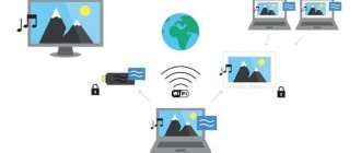
Methods for receiving digital broadcasts
Satellite TV
In this type of digital broadcasting, the signal is transmitted to special receivers using a receiving antenna, which is installed at the user's place, and satellites. In this case, it is very important that the antenna can operate with frequencies below 3 GHz. It is thanks to the satellite dish that the user can have access to a large selection of different television channels that are provided by operators. However, as stated above, such a service is provided only upon payment of the cost of the package or channel. Often, the user can purchase exactly any channel he wishes.
This type of television is not the most budget-friendly, since in order to gain access to watch programs, the user must first purchase all the equipment necessary for this.
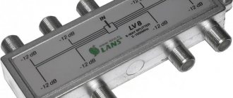
Cable TV
The signal in cable television is transmitted in the MPED-4 format, as well as due to the corresponding parameters of signal transmission on the Internet. The signal is also transmitted using coaxial cables, which must have a higher bandwidth and can be connected to a TV or receiver via an Ethernet port.
Access to cable television can also only be obtained if the necessary infrastructure is available. Also, in this case, as with satellite television, the user will have to pay a monthly fee for the services provided. Moreover, in order to switch to cable television, the user must first conclude the necessary contract for connection. Access to channels after the conclusion of the contract will be provided on the basis of previously generated packages.
Terrestrial TV
In this type, the signal is transmitted using repeater stations that are installed on the ground. The television signal is distributed by already assembled multiplexes, which combine 10 channels into one package. The operating principle of this television is practically no different from analogue broadcasting.
This type differs from those mentioned above in that the user can purchase an antenna at a fairly low cost, and no service connection fee is required.
Digital television signal generators
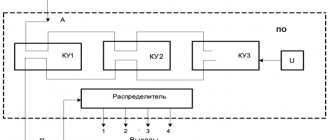
Let's consider two options for the block diagram of a digital television signal driver.
In the device shown in Fig. 2.1 a, the signals of the primary colors ER, EG, EB from the source of television signals (TV camera) first arrive at the gamma correctors (GK) . The generated signals E'R, E'G, E'B in the coding matrix (CM) are converted into a brightness signal E and color difference signals E'RY and E'BY . These signals are then converted by an analog-to-digital converter (ADC) into digital signals YD, CR and CB , respectively. At the ADC there are additional analog devices that perform scaling and shifting of signals in accordance with the ratios:
The number of bits of each ADC is in most cases 8 .
Clock pulses from the scanning device of the television signal source are supplied to a digital sync pulse generator (FDCS) , which produces the sync signals NAS and CAS . In addition, clock pulses are used to synchronize the clock pulse generator (GTI) , which generates pulses with frequencies of 27, 13.5 and 6.75 MHz , supplied to other nodes of the device. The GTI contains a phase-locked loop (PLL) , which provides the required number of clock periods during the horizontal scanning period of the television signal source.
Rice. 2.1. Options for the block diagram of a digital television signal driver
The multiplexer (MS) in a given sequence transmits the digital signals YD, CR and CB and digital clock signals to the output. , a digital television signal (DTS) is generated at the output of the device .
In another version of the generation device (Fig. 2.1 b), the signals of the primary colors ER, EG, EB are immediately converted into digital signals Rd, Gd, Bd . Moreover, each LCP must have at least 10 , and preferably 12, binary bits. Next, the digital signals Rd, Gd, Bd are sent to digital gamma correctors (DGC) , in which nonlinear transformations are performed. The number of binary bits that have undergone gamma correction of digital signals is 8 . Then the signals R'd, G'd, B'd in the digital coding matrix (DCM) are converted into a digital luminance signal Yd and digital color difference signals CR and CB .
The generation of clock signals and clock pulses and the operation of the multiplexer are carried out similarly to the first version of the device. Performing gamma correction digitally provides a more accurate specification of the required conversion function, but it requires more binary and therefore more expensive ADCs .
One of the phenomena that adversely affects the sampling process is jitter , which consists in the inaccuracy of discrete samples in time. With rapidly changing signals, jitter can lead to errors in the quantized values, which in turn leads to noise. [1, p. 49]
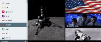
Frequencies of DVB-T2 digital television channels
To set up digital television, the user must know the frequencies of the television channels he needs. The table below shows the most popular TV channels and their frequencies.
It should be noted that the channels of the first multi-complex are provided free of charge, and for the remaining two the user will have to pay extra.
| Channels of the first multiplex | |
| Name of the broadcast channel | Frequency |
| 546 C30 |
| 546 C30 |
| 546 C30 |
| 546 C30 |
| 546 C30 |
| 546 C30 |
| 546 C30 |
| 546 C30 |
| 546 C30 |
| 546 C30 |
| Channels of the second multiplex | |
| Name of the broadcast channel | Frequency |
| 498 C24 |
| 498 C24 |
| 498 C24 |
| 498 C24 |
| 498 C24 |
| 498 C24 |
| 498 C24 |
| 498 C24 |
| 498 C24 |
| 498 C24 |
| Channels of the third multiplex | |
| Name of the broadcast channel | Frequency |
| 578 C34 |
| 578 C34 |
| 578 C34 |
| 578 C34 |
| 578 C34 |
| 578 C34 |
| 578 C34 |
| 578 C34 |
| 578 C34 |
| 578 C34 |
Connection and setup
Console
Each user can connect digital television at home without any problems independently. Before doing this, you need to make sure that the TV supports digital television transmission.
You can connect the set-top box to your TV as follows:
- First, the user must turn off the TV;
- After this, you will need to connect all the necessary cables from the coaxial antenna and the power supply to the set-top box;
- After this, you can begin connecting the TV to the set-top box. To do this, the user must connect the existing cables using one of the methods. Namely: SCART port, HDMI port or RCA port. It is very difficult to make a mistake at this stage, since all the wires have a special color and shape;
- If the set-top box has RF-OUT, the user can connect it to the antenna input for the TV. Thanks to this, the owner of the device will be able to view both analogue and digital channels;
- After this, the owner of the TV can turn on the device, and in the menu you will need to select the required port to which the receiver was previously connected.
TV
After connecting the set-top box, you need to configure the channels. This is done as follows:
- First you need to turn on all devices and open the “Settings” section in the set-top box menu;
- Next, you need to select the country and type of signal received;
- After this, you can start searching for channels; to do this, you just need to enable the “Automatic channel search” option;
- The set-top box will independently search for television channels, and after completion the user must click on “Save”. If the channels were not detected, the user can find them manually. To do this, you simply need to enter the frequencies of the desired channels.
4.7/5 — (24 votes)