The HDMI digital interface has firmly taken its place at the top of technology. Leading technical characteristics and constant updating of specifications have led to the high popularity of this method of data transmission. They try to use the HDMI interface in all cases where the equipment has suitable connectors for this. And even in cases where there is a socket on only one device, users prefer to connect via adapters, using this one. It is for this reason that the relevance of today’s article is greater than ever.
Despite the relatively low cost of adapters, many people prefer to repair them or even make them themselves. However, data transfer is a delicate matter, therefore, not knowing what and how to do, you can cause a serious breakdown. Therefore, theory comes first in this matter. First of all, you need to get an idea of how data transfer is organized. After this, the next step is to understand which contact is transmitting each type of data. In the field of electronics, this is called in one word - pinout. This is exactly what we will talk about. Let's figure out what types of connectors are found and how many contacts they have. It will also describe which contact is responsible for what. The HDMI cable pinout can help those who want to make an adapter or repair an existing one.
HDMI Pinout: Overview of Digital Interface Pinout
Before moving on to specific examples, you can get acquainted with the general principle of contact distribution. HDMI is a digital connector that supports the transmission of both video and audio data. On top of all this, some specifications support Ethernet connectivity, audio send back, and more.
At first glance, HDMI cable technology is similar in design to twisted pair cable, and there is some truth in this statement. However, in fact, the cable includes as many as 19 pairs, each of which is responsible for its own parameter. Among them you can find:
- Video channels
- Synchronization channels
- Internet channel
- Audio channel
- Nutrition
- Channels of sensors and detectors.
It seems that it is easy to get confused in all this. However, this is not quite true. Despite the presence of three form factors, the circuitry in them is approximately the same. Therefore, it is enough to understand the general principle in order to then use it in work or repair. This is exactly what we will do.
Repair work
Let's finally move on to the most interesting part of our article, find out what wiring an HDMI cable is and how the repair is carried out.
Tools
You don’t need many tools to get the job done, and many who are at least somewhat familiar with electronics will have what they need.
Measuring equipment
- Multimeter - with its help we will check the functionality of each contact and its location;
Convenient and quite powerful soldering iron
- The purpose of a soldering iron, we think, is already clear to everyone, the main thing is the presence of a sharp tip, because all the contacts are located very close to each other;
Take the option with thick blades
- Stationery knife - will be needed when removing the insulating sheath from the old connector;
For convenient work
- Wire cutters - will be needed to bite off the old connection;
High quality insulation
- Hot-melt adhesive - needed not only for insulation, but also for fixing thin wires;
Soldering Clamp
- It wouldn't hurt to have a soldering clamp. The price of this device is low, but it is not practical to purchase it if you don’t have it - it’s easier to buy a new cable. Soldering without it will be quite difficult, although you can figure out something similar in functionality from available items.
Naturally, you will need soldering consumables - solder and flux.
HDMI, mini, micro connectors and their pinouts
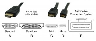
As already mentioned, there are several connector form factors. Form factor is nothing more than the dimensions of the connector and its parameters. In the case of HDMI, there are three of them, and none of them stand out in terms of technical characteristics. Each type has the same bandwidth and maximum resolution as specified. These are the types and their main purposes:
- Type A. Standard connector used in most types of equipment. The most common among its “brothers”. In everyday life it is often called full-size.
- Type C. Aka Mini HDMI. Used in tablets, video cameras and certain laptop models. So named because of its smaller size than type A.
- Type D. Micro HDMI. The smallest connector in the family. It was designed specifically for small devices like tablets, cameras and even smartphones.
Getting to know the types of connectors is one thing, and pinouting the HDMI connector by form factor is quite another. Next we will talk about each of these form factors, as well as one more guest.
Pinout HDMI Type A, 19 pin
The standard full-size connector has 19 pins, as the subtitle suggests. If you assign each contact its own number, you will be able to divide them into groups. Group 1 (pins 1-9) will contain video signal channels 0, 1, 2 according to the +/screen/- principle. Group 2 includes numbers 10-12. They contain the clock frequency (+/screen/-). The next group is service. This includes pins 13-16 and includes the CEC, SCL and SDA signals. We will include the remaining three contacts in the latter. Let's call this group Power, since it contains “Ground”, a power channel and a connection detector.
Now let’s list each contact separately with the assigned signature:
- Video (2+)
- Video (2 screen)
- Video (2-)
- Video (1+)
- Video (1 screen)
- Video (1-)
- Video (0+)
- Video (0 screen)
- Video (0-)
- Tact +
- Tact (screen)
- Tact –
- CEC signal (service)
- Utility
- SCL bus signal
- SDA bus signal
- Earth
- 5V power bus
- Device connection detector.
This circuit is convenient to use when repairing a connector. And also this is the HDMI - HDMI pinout.
Pinout HDMI Type B, 29pin
There is one more type of connector, which we practically did not touch upon due to its rarity in technology. We are talking about a large connector, the so-called Type B, which includes 29 contacts. In it, contacts 1-9 and 13-21 are responsible for data, 10-12 are reserved for the clock, 22 for SES. 23 and 24 are “empty”, reserved, 25 and 26 are SCL/SDA, and 27-29 are “Ground”, power and connection detector, respectively.
Pinout HDMI Type C (Mini), 19pin
Mini HDMI, or HDMI Type C, is a connector that is smaller in size. It differs little in width from the full-size one, but is greatly flattened in height. The form factor was introduced on June 22, 2006, along with the release of specification 1.3. The first technical characteristics, in fact, corresponded to this specification. Thus, the throughput increased and became 10.2 Gbit/s. The maximum possible interface resolution is 2560x1440. The main purpose for the release of the specification is video cameras. Over time, the scope of its application has expanded significantly. Now Mini HDMI is used to transmit signals from photo and video equipment, tablets and some laptop models.
Let's move on to the pinout itself. All contacts are located on the bottom of the connector. As in the full-size form factor, there are 19 of them. Here is the purpose of each contact in order:
- Date screen
- Date 2+
- Date 2-
- Date screen
- Date 1+
- Date 1-
- Date screen
- Date 0+
- Date 0-
- Clock speed screen
- Clock frequency +
- Clock frequency -
- Ground for DDC/CEC/HEC
- SES signal
- SCL
- S.D.A.
- Reserved for all cable types except HDMI+Ethernet
- Power supply 5V
- Hot plug detector (except internet standard)
Pinout HDMI Type D (Micro), 19pin
The size of equipment supporting digital data transmission has steadily decreased. In this regard, a short time after the release of the mini-plug, there was a need to adapt the HDMI cable for the smallest devices. Thus, with the release of specification 1.4, Micro HDMI appeared, which received the official name Type D. It is approximately equal in height to a mini-connector, but the width has decreased significantly. Thanks to this, it became possible to use it even in the smallest devices. Cameras, video cameras and other miniature devices now have the ability to instantly display their data on a large screen. The bandwidth of the specification allowed working with resolutions up to 4096x2160. This resolution can output the highest quality photos or videos directly from miniature equipment, without the need to transfer files to a PC or other storage device.
Like previous form factors, micro HDMI has 19 pins. For greater compactness, manufacturers have returned to the arrangement of contacts both at the top and at the bottom. Next on the list is the pinout with reference to numbers.
- Connection detector
- Reserved
- Date 2+
- Date 2 screen
- Date 2-
- Date 1+
- Date 1 screen
- Date 1-
- Date 0+
- Date 0 screen
- Date 0-
- Tact +
- Tact screen
- Tact –
- SES signal
- Grounding
- SCL
- S.D.A.
- Power supply 5V
Why solder the cable?
Many readers may have a reasonable question - why bother with soldering at all, when for quite modest money you can go and buy a new one, to which we will answer the following:
New HDMI cable
- Firstly , there is not always a store nearby where you can purchase such products, and such stores are not always open - this is especially true for villages and small towns.
- Secondly , not everyone wants to buy a cheap cable, especially if they had a good one before - we agree that the example is controversial, but still.
- Thirdly , imagine the situation that you already have two cables, and both have one broken connector and one working connector. Why not take it and make one working cable without spending any money? It's both interesting and economical!
- Fourthly , the length of the existing HDMI cable may simply not be enough for you, and you will want to extend it. Well, or the connector simply does not fit into the hole in the wall and you don’t want to expand this very hole.
In general, there can be any number of reasons, since situations sometimes develop in the most unexpected ways.
How to understand that the cause of the fault is in the cable
The photo shows a typical HDMI problem - a broken connector is bent, which often happens under the influence of the cable's own weight or when mounting the TV on a bracket where there is simply not enough space for it
How can a problem with a faulty cable manifest itself:
Don't confuse this - it's something with your satellite dish
- The TV displays the following message on the screen: “No video signal”;
Noise in the image
- The image is unclear, covered with noise, with a possible color shift towards blue, red or green;
The image was replaced by lines and stripes
- Instead of the usual picture, the TV gives you these artifacts in the form of stripes of squares and other patterns;
When the TV is silent
- The picture is there, but there is no sound.
- Other symptoms are also possible, but the essence is the same - first of all, the cables are always checked for functionality, and only then the equipment.
Wrong input selected
Don’t think that we are kidding, but indeed, very often, inexperienced users cannot understand that the active input on the TV has been changed. So if you see snow like this on the screen, then take the remote control, look for the button for changing inputs (if you don’t know it by sight, look at the instructions), which may be called “Input”, “TV\IN”, “Source” and other. Next, select the one you need from the list provided.
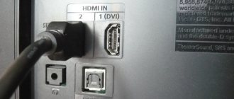
If you have ever held such a cable in your hands, you should know that its “body” is made quite strong and flexible, so if there is no visible damage on it, the problem may only be related to the connectors. How can you be sure there is a problem?
Here are short but effective instructions:
- First of all, try to slightly move the connector plugged into the TV.
- If nothing happens, then pull out the HDMI and plug it back in - sometimes such measures help restore image and sound, since it often happens that there is no normal contact.
- The next step is to change the cable and input, for example, connect tulips, which are still equipped with most video equipment. If the image is restored, then conclusions can be drawn.
- Do a visual inspection of the connectors - they may be bent or even torn off. All questions are immediately resolved here.
It also happens
Advice! The HDMI “female” connector, which is installed on TVs and receivers, breaks down very rarely; most often the problem occurs with the cables, although it would not hurt to conduct a visual inspection of these elements.
HDMI cable pinout by color
Like all digital interfaces, HDMI video data is transmitted using the RGB system. In this color system, the primary colors are red, green and blue. Therefore, three twisted pairs are required to output the image. Each of them is protected by its own screen. Accordingly, we get three groups of 3 wires, which gives a total of 9 contacts. For ease of wiring, they are combined into color groups. Below are these groups by contact numbers:
- Contacts 1-2-3 (2-1-3 in mini and 3-4-5 in micro) – red group
- Contacts 4-5-6 (5-4-6 in mini and 6-7-8 in micro) – green group
- Contacts 7-8-9 (8-7-9 in mini and 9-10-11 in micro) – blue group.
Typically, the positive wire of each group is colored white, while the negative wire is the color corresponding to the group. This is done to make HDMI wiring easier and faster, and there is less chance of making a mistake.
Replacing connectors
If the break is located near one of the connectors or the decision is made to replace both of them, the conductors must be soldered directly to the connector pins. The ideal option is to have a detachable connector, the contacts of which can be soldered to the corresponding conductors. If there is none, you will have to remove the old HDMI connector and use it, even though the manufacturer claims that it is disposable.
For ease of use, it is better to immediately bite off the HDMI connector. Using a sharp knife, cut the polymer shell along the adhesive seam and remove it. Under it there is a continuous layer of hot-melt adhesive, which the manufacturer used to fix and at the same time insulate the conductors.
Using the same knife, remove the glue and expose the contact pads. If you use the same cable, there will be no difficulties; you need to gradually solder the conductors one after another, guided by the color of the insulation.
If the task is to solder two cables into one, or a connector from another device is used, this approach may not work. Conductors from different manufacturers will most likely differ in color. You can't do without a multimeter here. Methodically calling each conductor, you need to select the ones you need and solder them with all possible care.
After all the conductors have been soldered, you need to once again check the correctness of the connections using a multimeter.
Even if the outer insulation of the HDMI connector was removed very carefully, it is unlikely to be reused. It’s easier and more reliable to fill the soldering area with hot glue, let it harden, and then carefully form the body of the new connector with the same hot glue. The glue can be hidden using heat-shrinkable insulation of a suitable diameter or wrapped with electrical tape.
HDMI cable pinout for audio
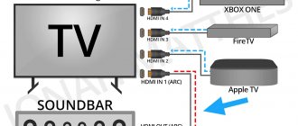
The need to become familiar with audio channels may arise if one of the devices for some reason does not output audio transmitted via the multimedia interface. This happens more often with HDMI than with DisplayPort, since multimedia does not take into account the subtleties of manufacturers. One way or another, there is a way out. To avoid the hassle of soldering together many connectors, we recommend using a ready-made option. You need to purchase an audio adapter. Its role is to extract audio from data and transmit it in analog or digital format. This method is much more reliable and also helps save money. Special attention should be paid to pin number 14. In full-size HDMI specifications 1.4 and later, this channel is reserved for ARC technology. This audio return channel eliminates unnecessary wiring by carrying audio data in two directions. You can and should use it, because using ARC is a powerful tool that can simplify your life.
Types of HDMI sockets
When carrying out renovations in an apartment, you should think in advance about the possibility of installing such sockets near the proposed video equipment. Let's consider 2 main types of these devices.
Passive HDMI sockets
Depending on the installation location and purpose, such sockets can be receiving or transmitting. These are the cheapest devices, the peculiarity of which is the inability to broadcast a high-quality signal over a distance exceeding several meters.
Active HDMI sockets
The main difference between these devices and sockets of the previous type is the amplifier, which significantly increases the signal transmission range (up to 45 meters). In addition, to connect active HDMI outlets, you do not need to use a special cord, since this is done with twisted pair cables. Of course, this connection method cannot be called optimal, but it is often used due to the high cost of the HDMI cable.
USEFUL INFORMATION: Pull-out socket block in the countertop
Since the cost of the modification with an amplifier is much higher than its passive counterpart, in most cases it is used only for installation at the output of the receiver, and a connector without an amplifier is installed on the panel of the multimedia device. Moreover, in the case of using active sockets on both sides, the video signal transmission range increases significantly.
HDMI – DVI pinout
If we talk about adapters, then most often you need to connect HDMI to a monitor that has an old-style digital interface. As a rule, this is DVI - a standard that appeared quite a long time ago. However, its technical characteristics allow it to process high-resolution and clear data. The similar format of the transmitted data eliminates the need for complex conversion. A properly wired adapter of cable and two plugs is enough. Of course, it is worth considering that DVI does not support audio transmission. Therefore, you will either have to abandon it or use the above-mentioned sound adapter.
To assemble a working adapter, you need to connect the contacts as follows:
| HDMI number | DVI number |
| 1 | 2 |
| 2 | 3, screen |
| 3 | 1 |
| 4 | 10 |
| 5 | 11, screen |
| 6 | 9 |
| 7 | 18 |
| 8 | 19, screen |
| 9 | 17 |
| 10 | 23 |
| 11 | 22, screen |
| 12 | 24 |
| 13 | No analogue |
| 14 | No analogue |
| 15 | 6 |
| 16 | 7 |
| 17 | 15 ("Earth") |
| 18 | 14 |
| 19 | 16 |
Characteristics of video cables and adapters.
Type.
Video cables are designed to connect two elements of a video system. Typically, both sides of such a cable have connectors of the same type. However, it often happens that the video cable is also an adapter.
An adapter is a device designed to move from one type of connector to another or, for connectors of the same type, from one type to another (from a plug to a socket or vice versa).
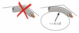
The length of the cable should be selected so that it is sufficient for the required connection with a small margin. It is not worth taking a cable that is too long unless necessary - even the best cables reduce the level of the useful signal, and the longer the cable, the more.
Ferrite beads or shielding are a way to protect the transmitted video signal from electromagnetic interference. It should be borne in mind that shielding as protection against interference will be ineffective if the equipment is not grounded.
The PVC insulation of conventional video cables is quite rigid; such cables have little flexibility, which can be inconvenient. Rubber insulation itself has poor resistance to mechanical stress, but placing it inside a fabric braid protects the cable from mechanical damage, maintaining its flexibility. The aesthetic role cannot be denied - a fabric-braided wire looks more beautiful.
Connectors.
To understand which connectors can have adapters from which ones, let’s divide all connectors into groups that use compatible data transfer formats.
Component video is a method of transmitting an analog video signal over two or more channels, each of which carries some separate information about the color image.
Composite video is a method of transmitting an analog video signal over one channel.
Working adapters are only possible within one group.
TS, TRS, TRRS (Jack 3.5 mm) are used to transmit analog video signals. Typically, such a connector is installed in miniature devices (camcorders, cameras, recorders) due to its small dimensions. There is no single standard for wiring such a connector for transmitting a video signal, nor is there a standard for the video signal itself - both component and composite video signals can be transmitted through such a connector. It is strongly recommended to use adapters and video cables with a jack connector only with the equipment that came with it. Before purchasing a new adapter, you should find out exactly how the connector in the adapter is wired, how the signals are routed on the connected device; make sure that the wiring matches and that the video signal standards on the connected devices match. The most common adapters: TS – RCA, TRRS – 3 x RCA.
RCA (Phono) are used to transmit analog signals - component YPbPr and composite.
The YPbPr component video signal contains information about brightness, blue and red color levels. Of the common analog standards, YPbPr and VGA provide the best quality. To transmit such a signal, three RCA connectors are used, usually marked with colors and/or letters - green (Y), blue (Pb) and red (Pr).
A composite video signal contains all video information in one channel, which has a bad effect on image quality: of all video signal transmission standards, composite provides the worst quality. For such a signal, one yellow RCA connector marked “video” is used.
Despite the identical connectors, the standards are incompatible; it is impossible to connect a component output to a composite input (and vice versa) using an adapter.
The most common adapters: RCA - SCART, TRS - RCA, TRRS - 3 x RCA. For adapters of the last two types, you should make sure that the adapter is wired correctly in relation to the equipment used and that the signals on both sides of the adapter are consistent.
SVGA (VGA) – used to transmit a component analog RGB video signal containing information about the brightness level of three primary colors: red (R - Red), green (G - Green) and blue (B - Blue). Provides (together with YPbPr) the best quality of common analog standards.
The most common adapters: SVGA - DVI-I, SVGA - Displayport
DVI connectors can be used to transmit analog RGB signals (DVI-I), digital (DVI-D), and both together (DVI). Because of this versatility, some confusion arises with adapters: the presence of SVGA-DVI-I adapters on sale leads many to believe that signals from SVGA and DVI connectors are fully compatible. This is not true - only the analog part will work in such an adapter and an attempt to connect a purely digital output to, for example, the analog input of a monitor will be unsuccessful.
The most common adapters: DVI-I – SVGA, DVI-D – HDMI, DVI – Displayport
HDMI, miniHDMI, microHDMI – used to transmit digital video and audio signals. Accordingly, the adapter can also only be for a connector that allows the transmission of a digital video signal. In an HDMI-DVI adapter, only the digital part will be used and such a device is not suitable for pairing analog and digital signals.
There are several versions of the HDMI format, but the connectors and their wiring are the same for all versions. When it comes to cables, older versions of HDMI have higher bandwidth, so they place higher demands on cable quality. cable standard speaks more about the quality of the cable than about its compatibility with a particular version of HDMI.
Pinout of HDMI connector to RCA tulip
Creating an adapter is also possible in the case of using a tulip. This adapter is not used very often, and it is not that expensive on sale. Therefore, it is better to purchase a finished product than to bother making a homemade device. Nevertheless, this is also possible. It is not for nothing that we cited above the division of contacts by color. Each color has its own channel in the RGB system. This may help in creating an RCA tulip adapter. Each color group is connected to the corresponding “tulip”, and the sound is output separately.
It is worth noting that the data format in the two connectors is different, and therefore it is recommended to use purchased adapters containing conversion boards.
Making your own cable
Making an HDMI cable at home is not a big problem. Key Features:
- the maximum cable length is 10 m;
- HDMI wiring is difficult due to its small size; additional cambric protection may be required;
- The individual socket contacts are numbered from right to left, with odd-numbered contacts in the top row and even-numbered contacts in the bottom row.
Assembling a homemade cable is simplified by HDMI sockets with numbered crimp contacts.
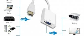
HDMI to VGA adapter pinout
An adapter to VGA is something that cannot exist in nature. The two interfaces use too different data formats to be connected together so easily. This requires several complex boards, which are extremely problematic to solder on your own. It is recommended to use purchased adapters - it is fast, simple and reliable. When making such an adapter yourself, it is very easy to confuse something, which can lead to problems with the equipment.
So, how to properly crimp wires with lugs
In addition to selecting the necessary wires and tips, to perform this task you will need a special tool called a “crimper” or press pliers.
Externally, the tool is very similar to pliers, at the ends of which a special matrix is installed, into which the tips and the non-insulated part of the cable are inserted.
This tool is designed to provide uniform ferrule force around the wire, eliminating poor contact when crimping the cable. In addition, there are universal tools that allow you not only to crimp, but also to cut the cable, remove the insulation from it and twist the core.
Particular attention should be paid to the type of cable; in domestic conditions, the power cable can be of two types:
- with a monolithic core;
- stranded
When crimping a wire with a monolithic core, it is enough to remove the insulation layer with a small margin (up to 0.3–0.5 cm), (using a tool or using an insulation stripping knife), then straighten and degrease the area to be worked with, after which you should put it on a thermal insulating tube onto the cord.
Then, we select on the tool (by a jumper in the matrix) a certain section and type of tip. After carrying out the above manipulations, you need to insert the prepared end of the wire into the tip, after making sure that there are no cracks in it.
Install the ratchet lock lever. Failure to comply with this point may result in poor-quality crimping of the tip and, accordingly, poor quality of the connection.
The final part of crimping a wire with a monolithic core with a tool:
- make sure the connection is correct;
- insert the tip all the way into the device so that the numbers with the matrix markings are knocked out on the front or back sides of the tip;
- completely recess the exposed section of the wire into the tip;
- applying force, press the crimper handles;
- as soon as the operation is completed, the handles will automatically begin to return to their original position (to do this, it is necessary to move the ratchet locking lever to the “locked” state);
- The cord has been terminated; the final step is to put the heat-shrinkable braid on the connection point and warm it up with a special hairdryer or lighter.
If the handles do not return to their original position, then this problem may be caused due to the following problems:
- too weak compression of the tool handles;
- malfunction of the ratchet mechanism;
- “weak” spring in the ratchet;
- The ratchet locking lever is not fully installed.
If you have to terminate multi-core wires, then the above method should not be used, as it has many nuances.
Therefore, wires with a large number of cores are crimped according to the following instructions:
- remove part of the insulation from the wire (with a small margin of up to 0.3–0.5 cm); when removing the insulation, it is highly advisable to use a special tool that allows you to remove the braid and not damage the cable cores, but if such a tool is not available, you can use a sharp knife (when removing the insulation, you should make sure that the wire cores were not affected);
- put a small piece of thermal insulating braid on the cord;
- after which the bare area must be degreased with alcohol and a special electrically conductive paste applied (the most common options are compositions such as “KVT” and “EPS”).
After the above manipulations, cable processing can be considered complete.
- set the required cross-section and type of tip in the device matrix;
- install the tip completely into the device so that the numbers with the matrix markings are on the front or back sides of the tip;
- we insert the straightened cable cores into the lug until it stops ( Attention! Twisting the cable cores is prohibited );
- applying force, press the crimper handles;
- The crimping of the stranded wire is completed, now we return the heat shrink that was previously placed on the cord to the connection point and warm it up with a hair dryer, soldering iron or turbo lighter;
- After completing the operation, the handles should return to the standard (unclamped) position; if this does not happen, then the reason for this may be the problems described above.
HDMI to Mini HDMI adapter
Things are completely different with other form factors. They are in the same standard, use the same formats and encryption, and also have the same characteristics. All this makes it possible to create adapters without difficulty. In order not to confuse anything, it is enough to remember that in a group of three contacts the order changes slightly. In the full-size connector, the screen contact is located in the second place out of three, and in the Mini – in the first. In addition, “Ground” in the mini connector is located on the 13th pin, CEC is on the 14th, and the 17th is reserved.
HDMI sockets for hidden wiring from Legrand
More difficult is the installation of HDMI sockets, the design of which does not provide for the use of plug connectors to connect a cable to them.
To understand the connection procedure, you should first familiarize yourself with their design. To illustrate the design of an HDMI socket, consider a product from the French company Legrand, which is one of the world leaders in the production of electrical equipment.
Today, electronics stores offer several lines of HDMI sockets from Legrand, which differ in the material and shape of the housing, as well as the decorative panel. These devices combine high quality manufacturing and maximum reliability.
Such sockets are complete products, which include a working part consisting of a printed circuit board with 19 pins and an HDMI connector, a device for mounting in a socket box, as well as a decorative panel.
USEFUL INFORMATION: Installing a socket box in a concrete wall
The front panel of the product can be selected in accordance with the customer's wishes. This gives you the opportunity to select an outlet that best suits the interior of the room in which it will be installed.
Another important advantage that distinguishes the model in question is the ability to install it on any wall, and not just on a special block, like most existing models of this type.
The products of another French company, Schneider Electric, also have decent quality.
Repair of other types of connectors
With a little time and effort, you can independently solder most of the connectors used in everyday life, for example, BNC solder connectors. This type of connector is used in television systems and video surveillance systems. Both Male + Female kits and a separate socket or pin are available for sale. It's not difficult to solder them. The central wire must be soldered to the connector contact, the screen must be soldered to the body.
USB connectors are widely used in computer technology. With their help, almost all modern peripheral devices are connected. It is not difficult to replace a failed connector; ready-made dismountable plugs are available for sale, both standard size and micro format.
Knowing how to use a soldering iron is a useful skill. With just a little effort you can easily handle any minor repairs.
Damaged HDMI, VGA cords, connecting wires for power supplies, mobile phone chargers, all of this can be soldered. And this is not a matter of saving, most of these connectors and wires are not very expensive, this is a way to get out of a difficult situation if there is nowhere and no time to buy a replacement, and it’s just an opportunity to do something with your own hands.