home
Articles
Dividers or splitters for television cable
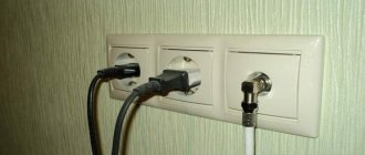
If you only have one TV connected in your house, then there are usually no problems. In this case, the television signal enters the television receiver directly from the antenna. The problem comes when you want to watch two or more TVs. You don't have to buy a separate antenna for each of them. A TV cable splitter will come to the rescue - a small-sized device that will completely solve this problem.
The “magic” foreign words “splitter” and “diplexer” are called, respectively, an ordinary antenna splitter for digital television or a combiner of two different signals. Among cable operators, these devices are often referred to as “crabs.”
How the satellite system works
The satellite television system consists of several devices, these are:
- Antenna dish;
- Receiver (tuner);
- Lightning protection;
- TV cable;
- Splitter (divider).
Antenna dish
The receiving device looks like a concave metal disk that is mounted on the wall or roof of the house. The satellite antenna is oriented towards the satellite orbit. There are mobile models that are equipped with an electric motor and can be turned in any direction at the request of the owner.
Receiver
The tuner, or receiver, is the main part of satellite equipment. Its functions include signal amplification, tuning to a specific frequency, and filtering interference. The tuner displays the settings menu on the TV screen. Using the remote control, you control the receiver, selecting your preferred channel with different adjustment levels.
Lightning protection
Manufacturers install lightning protection elements on the amplifier board in the form of two glass diodes. The protection is designed to localize static discharges that occur during a thunderstorm. This device will not save you from destruction from a direct lightning strike on the plate.
Protection in the form of a barrel with F connectors is built into the TV cable. It takes on a powerful thunderstorm impulse. The part burns out, but does not allow the destructive energy flow to penetrate into the receiver and TV.
TV cable
A television cable is a transmitter of a TV signal between satellite, terrestrial and wired television segments. The main core is enclosed in a dense vinyl sheath, on top of which there is shielding in the form of a braided braid made of thin aluminum wire. In turn, the top of the antenna cable is covered with plastic insulation.
Splitter (divider)
The device distributes a signal to several television receivers. It is built into the cable between the tuner and TVs.
Prime divisor
What is a TV adder for?
The summing device I offer allows you to sum the signals of two antennas into one cable.
Of course, I'm talking about the case where two signals are at different frequencies. True, the same cable is used by those who
has an old TV with two antenna input jacks, so as not to run two cables to the TV.
In this case, in front of the TV, the signal again branches into meter and decimeter. Proposed
the device can sum the signals. What is a TV adder?
See the factory-made adder (divider) circuit here.
Let's take it 4
a piece of MGTF wire. This is a copper stranded wire in fluoroplastic insulation. There are these wires
several types, and there are no special restrictions or requirements for their use, but with thick conductors it is not worth it
apply. That's why I don't write wire brands. For example, I used MGTF, in which: the number of cores - 19
,
diameter of one core - 0,14
mm.
The length of the wire sections is 100.110 mm.
Outer diameter (fluoroplastic) —
80 mm long
and insert 4 pieces of wire into it. Choose a casing so that there are 4 wires
They hugged them well and were pressed tightly against each other. In such a cambric it is quite difficult to walk straight and
place 4 wires in parallel without twisting, so I usually take small rings of cambric. These
I pull the rings sequentially onto the wires, keeping them straight and parallel. A set of such
rings is 80 mm.
Rice. 1
TV adder. TV adder. TV signal combiner. How to connect two antennas.
You can use heat shrink tubing instead of cambric. Place 4 wires in it and heat it up. Such
the tube presses the wire tightly. Without waiting for the tube to completely cool down, give the product an arc shape.
This will make it more convenient to carry out subsequent wiring with a minimum length of installation wires.
Clean the wire leads and solder them as described below.
Rice. 2
TV adder. TV adder. TV signal combiner. How to connect two antennas.
Let's consider the wiring of a TV adder using the example of summing signals from meter and decimeter antennas into one
Solder the leads together 1
and
3
.
the central
core coming from
the decimeter wire
to this point 2 together.
and
4
.
the central
core going
to the TV
at this point .
1a together
and
3a
.
Connect this point to
the soldering
2 - 4
with a piece of any wire.
2a together
and
4a
.
the central
core coming from
the meter
to this point .
Connect the screens of three television cables together by soldering.
If the screen (or foil) cannot be soldered, then tightly wrap it with copper wire and fix it with soldering. Then
solder these wires. The soldering points are well sealed. Of course, both antennas must be matched to
with your TV cables! See the factory-made adder (divider) circuit here.
You can sum any two television signals transmitted at different frequencies.
If you need programs for calculating antennas for analogue and digital television, mobile
How to make any antenna?! All materials on antennas » » » here.
For channel frequencies and wavelength λ, see » » » here.
See a simple zigzag antenna here.
The general concept of antenna splitter (crab) means three types of devices:
- splitters (dividers);
- diplexers (adders);
- couplers (tap).
Each of them serves to solve specific problems.
What is an antenna divider?
Dividers are devices of 3 types:
- dividers (splitters);
- taps;
- adders.
Dividers
TV antenna signal amplifier
Splitters evenly divide the incoming signal into several channels. The incoming signal level of 12 dB will be divided into 2 TVs of 6 dB each. Accordingly, 3 TVs will account for 4 dB. The signal will be divided into 4 consumers - 12/4 = 3 dB.
Couplers
The devices are designed for mainline TV signal distribution. They are used in apartment buildings. The communal supply scheme is that antenna splitters distribute the incoming impulse floor by floor, where it is “met” by a coupler to all apartments located on the site.
Important! One type of tap is a blocker; it is used by cable television operators. The selector separates social and paid connection packages.
Adders
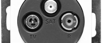
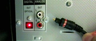
They are also called diplexers. They are used in cases where it is necessary to combine satellite and terrestrial antenna signals in one cable. The bottom photo shows two inputs “Sat” and “Ant” for a satellite and a regular antenna.
Diplexer
The adder can also work as a divider. By connecting the input signal cable to the device, you can get a division into 2 TVs.
How to avoid a drop in signal level when installing a splitter
With a high-quality antenna and two TVs in the apartment, the user may not notice any problems after installing a simple splitter. However, in a large house there will definitely be network points where the drop in signal level at dividers and splitters will be excessive. There are several ways to avoid problems.
- Installation of passive signal amplifiers. They are mounted in front of the consumer and do not require power. The devices compensate for wave losses in the cable and are indicated when there are reception problems only on certain channels.
- The use of active amplifiers. They are also installed in front of the TV. Devices of this class produce an increase in signal level and are indicated in situations where the picture freezes on all channels, the required 20 digital broadcasts are not detected when searching, and other serious problems arise.
It is always worth remembering one thing: the more splitters, splitters, signal amplifiers in the network, the higher the distortion will be . To optimize the level of losses, it is highly recommended to reduce the length of lines, use a minimum number of switching points with F-connectors, and lay the cable away from 220V power wiring and other sources of interference.
If you only have one TV connected in your house, then there are usually no problems. In this case, the television signal enters the television receiver directly from the antenna. The problem comes when you want to watch two or more TVs. You don't have to buy a separate antenna for each of them. A TV cable splitter will come to the rescue - a small-sized device that will completely solve this problem.
The “magic” foreign words “splitter” and “diplexer” are called, respectively, an ordinary antenna splitter for digital television or a combiner of two different signals. Among cable operators, these devices are often referred to as “crabs.”
Difference between splitter, combiner and splitter
Setting up an MTS satellite dish
A splitter is a device that divides the signal between outputs in equal shares. The coupler has an uneven signal output level. Much lower power transmission will come from the tap than will occur from the output connector. Such devices are used to distribute TV signals in multi-storey buildings.
For example, a tap is connected to the floor wiring, and the signal coming from the output will be transmitted to the next levels of the building. Thus, it is possible to connect numerous consumers without losing the quality of the received television signal.
Adders combine incoming pulses from different receiving devices so that the subscriber can alternately view programs from a satellite, cable or terrestrial antenna.
DIY antenna splitter
Anyone can make a splitter on their own. But before you begin development, it is important to know that such a device is applicable to an analog television antenna.
It is impossible to make such a divider or adder for digital TV.
Cheap Chinese devices have large losses in transmission quality, so it would be reasonable to improve them. To do this you will need a coaxial cable and a ferrite ring.
You can assemble the antenna splitter in a small metal box, and you should pay attention to the location of each connector.
In addition, the quality of the transmitted signal from a homemade splitter can be affected by a poor connection between the plug and the socket. Also, it is worth paying attention to the cable resistance.
It would not be superfluous to ground the homemade device and insulate the cable.
Active or passive
Antenna power supply
Which crab is better to choose: active or passive? The solution to this issue depends on the strength of the received TV signal. A passive crab simply divides the signal equally between two, three or more TVs. They are installed where signal amplification is not required.
It’s another matter if the level of television signal transmission leaves much to be desired. This is where a crab with an amplifier comes to the rescue. Its task is to compensate for the loss of dB during signal separation. Splitters with an amplifier have cords for connecting to a 220 V power supply.
Active splitters are connected to the antenna cable and TV in residential areas. Such devices are not used in administrative and civil buildings; special amplifiers for public use are used there.
Stationary TV signal amplifier
Installation Rules
The rules for installing dividers on two, three or more digital broadcast televisions are based on the structure of the cable network. It can always be considered as a collection of several segments with one of two standard types.
Equilibrium structure
The most clear example of a balanced network is an antenna installed on the roof and cable routing through the ceiling of the top floor of the house. In this case, the length of the leads to the consumers is almost the same. This means that it is enough to install dividers to evenly distribute the signal between TVs.
Characteristics of splitters
These include:
- throughput;
- attenuation level;
- presence of an amplifier.
Bandwidth
On the splitter body, the manufacturer indicates the frequency range of the device’s throughput. The universal satellite splitter, which perceives a frequency band from 5 to 2500 MHz, has good qualities. This makes it possible to simultaneously combine satellite and terrestrial TV signals.
Attenuation level
What matters is the level of attenuation. The smaller it is, the less noticeable the loss in video picture and sound quality will be. This parameter is often determined by eye. If signal attenuation is clearly visible on the screen (loss of image quality, sound distortion), then signal amplification will be required.
Availability of amplifier
When choosing a splitter, you need to determine the need for a built-in amplifier. It may be needed when connecting four or more TVs. The high-frequency amplifier requires power from the electrical network. This circumstance must be taken into account, since it is necessary that the power cord of the device does not create inconvenience during installation.
Do it yourself
It’s not difficult to make a splitter for analog television with your own hands; here are some simple diagrams of such a device.
Passive splitter with resistors.
Separator circuit for two and three devices
The figure shows two diagrams:
- a – for connecting two TVs (R1, R2, R3 = 25 Ohm);
- b – for connecting three TVs (R1, R2, R3, R4 = 36 Ohm).
Below is an example of a printed circuit board layout for circuit “b”.
Splitter board for three devices
The assembled device must be placed in a special case (any metal box will do for this), which should preferably be grounded. If the grounding is incorrect, interference in the form of snow may occur. Actually, it is better not to ground at all than to do it incorrectly.
If the image on the TV screen is double, you should put a ferrite ring on the coaxial cable between the splitter and the TV.
Active splitter circuit.
In cases where you have a low level of the incoming television signal, you can correct the situation using a divider that has a broadband frequency amplifier. The diagram of such a device is shown in the figure below.
Divider circuit with antenna amplifier
Parameters of the elements indicated in the diagram:
- R1-10 Ohm;
- R2, R4, R5 – 430 Ohm;
- R3 – 30 kOhm;
- R6 – 150 Ohm;
- R7 – 470 Ohm;
- R8-R10 – 43 Ohm;
- C1, C2, C4 – 150 pF;
- C3 – 0.01 µF;
- VT1 – VT2 – KT399A;
Choke L1 is a frameless coil wound with PEV-2 wire with a cross-section of 0.4 mm, the diameter of the coil is five millimeters, there are 4 or 5 turns.
You can use batteries to power the circuit, but it is better to take a power supply for this. In the latter case, the transformer may create interference, so it is advisable to place the power supply in a separate housing. That is why it is advisable to install the splitter in a wireless zone, that is, where there is no electrical wiring.
Note that the above antenna splitter circuits have proven themselves to be effective in dividing analog signals; as for satellite and digital television, it is better for them to buy a ready-made device than to make it yourself.
Selecting a TV cable
In technical documentation, a television cable is called coaxial, that is, a coaxial structure. The central core and braid along the entire length of the communication ensure transmission across the entire cross-sectional width in one direction.
A TV cable is characterized by the presence of four characteristics:
- The main core is made of copper.
- Core covered with foamed polyethylene.
- Screen made of twisted tape, foil or aluminum wire braid.
- The outer shell is made of PVC.
Note! A good antenna cable differs in the metal of the core, the composition and density of the screen, and the type of outer coating. High-quality products are characterized by the presence of a copper core, aluminum wire braid and a rubberized sheath.
Twist
The connection cannot be used for dissimilar materials, for example, copper and steel, or aluminum and copper. In the future, this will lead to oxidation and, as a result, contact breakdown.
The operating technology is very simple:
- perform stripping;
- Twist the wires, wrap them with high-quality electrical tape in several layers;
- twist the screens and also wrap them with insulation on top.
This can be done using the same algorithm as soldering (see above).
How do dividers work?
There are times when they try to connect two cables in parallel directly to the antenna in order to connect 2 TVs. In principle, this is possible, but it will not be possible to obtain the desired result. The fact is that any wired product has its own characteristic impedance. At the cable design stage, technologists lay down characteristics that ensure equal wave impedances of 1 cable and 1 TV.
When several TV signal conductors are directly connected to the antenna, the TVs will not broadcast anything. To prevent this from happening, coaxial cable splitters (dividers) with calculated characteristic impedance are used. Splitters divide the signal into equal parts, equalizing the impedance levels with that of the signal source.
Connecting to a splitter
Nowadays, no one can be surprised by the presence of a TV in every room. A small problem is supplying a TV signal to all receivers, since in most cases there is only one signal source. The solution to this problem is to use an antenna splitter. The picture quality when connecting TV receivers through a splitter may deteriorate somewhat, but the connection process itself is not difficult and is completed in just a few minutes.
The connection diagram can be presented step by step as follows:
- choosing a location for the splitter and securing it there;
- removing plugs from used connectors;
- cutting and connecting TV cable.
You must first decide where you will cut the television cable for further connection of two television cables to the television signal divider. You will have one common television cable that receives the signal from the television antenna, connected to the television signal divider socket.
How to connect the plug-to-television cable
In addition, it is necessary to have another TV plug available. To solder a television plug, you need:
- remove a small part of the cable insulation;
- unwind the outer braid of the cable;
- twist the braid and etch with soldering flux;
- Solder the outer braid to the outer contact of the plug.
The internal wire of the television cable, after it has been moistened with soldering flux, is soldered to the internal contact of the plug.
The connection of television cables to a television signal divider is carried out with the initial removal of a section of cable insulation.
Now, let’s take a look at the diagram for connecting two TVs to one antenna.
Connection diagram for two TVs to one antenna
Connections from one common TV cable are shown here:
- for two TVs;
- for three TVs.
How to choose the right splitter for TV
When choosing a splitter, you should take into account the need for the number of required ports. For example, there are two televisions in the apartment, the owner plans to purchase two more devices, then a divider with four output connectors will be needed. That is, the splitter must have 5 ports.
On the Russian radio market, dividers are purchased for connecting to two, three or more televisions. One splitter can have 16 ports. When purchasing, you need to make sure that the required operating frequency range is marked.
Additional Information. The most common operating range of divider frequencies is from 5 to 860 MHz. This allows you to watch high-quality TV programs in DVB-72 format.
How to connect two TVs to one antenna
A family dinner while watching the evening news broadcast - such a picture can be seen in almost every kitchen window of an apartment building. It is no longer a luxury to have a TV in the kitchen. Watching your favorite TV series and talk shows can brighten up the routine kitchen chores of every housewife. Progress has confidently crossed the threshold of every home and apartment, and now instead of a black-and-white large-scale TV, in many houses you can see a flat TV panel on the wall in every room.
Every owner of a second, or even a third TV, naturally faced the question of how to connect two TVs to one antenna? If this circumstance puzzles you, then read this article. It contains the solution to this simple problem.
Crab mounting options for TV antenna
Depending on the conditions and requirements for the interior of the room, installation options for the crab can be as follows:
- If the television cable is laid in the wall, then at the place where the splitter is inserted, the groove is opened and expanded to the required size. When restoring the finishing coating, it is better to close the opening with a decorative cover. You can quickly and easily replace a device or connect an additional channel;
- External wiring with a divider is done in non-residential rooms. Where it is impossible to spoil the interior of the office space, cables and dividers are hidden in plastic boxes;
- For floor wiring, the cable and splitters are placed in special channels inside the baseboards.
When to connect the wire
There are three common situations where a coaxial cable connection is needed.
- Complete break or partial damage to the cable antenna line. The wire transmits an ethereal signal, which is very sensitive and can be attenuated by the slightest factors. Therefore, if you see some very vulnerable spot on the line, where the wire is barely holding on, it is better to cut it and connect it again.
- It is necessary to extend the antenna cable for the TV. It often happens when television equipment is moved to another place in the room. Accordingly, the previously laid wire may not be enough. Then you have to lengthen the wire. A second piece is connected to the end of the previous cable to reach its destination.
- Connecting an existing wire to another television receiver. Instead of installing a separate antenna for each TV, you can connect to an already working one. Then a wire is drawn from the new TV, which connects to the line running to the apartment or house.
Connection method
Manufacturers of splitters, dividers and adders make sure that the device can be installed or dismantled quickly and efficiently. For this purpose, the crab ports are equipped with F connectors with external threads.
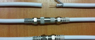
Cable ends ready for connection
The connection is made as follows:
- The ends of the cables are stripped so that the bare core protrudes from the sheath by 1.5-2 cm.
- Slightly stepping back from the edge of the cut core insulation, peel off the surface coating to expose a 1.5 cm long braid.
- The braid is wrapped around the insulation.
- The end is inserted into the counter F connector so that the connection is sufficiently tight.
- The connector nut with internal thread is screwed onto the desired splitter port.
F connectors
Old-style utility TV signal routers require soldering of stripped cable ends or have special clamping brackets.
Solder connection
You can take the easiest route and solder without any problems. Simply expose the conductive parts of the wire (shielding layer and copper core). Next, solder the wire and rewind it with electrical tape. Then do the same with the braid, cover with insulating tape. The option is working, but unprofessional.
Soldering can be done much more accurately, maintaining maximum joint quality. First, text instructions are provided, and then a step-by-step gallery of pictures is located.
- Make a longitudinal cut of the shell to a length of 50-60 mm.
- Bend the shell along with the entire shielding layer back.
- Cut about 20 mm of internal insulation from the conductor. The shortening is done so that after joining the core for connecting the screen there is a reserve.
- Position the cables so that the sides of the outer cuts face each other. From the inside, half expose the core by making a transverse cut of 20 mm.
- Bend the insulation away from the core to make it easier to work further.
- Solder the wires together along all available lengths.
- Align the core so that it is flush with the rest of the wire. The insulation halves must fit together. If there are any excess pieces left on top, cut them off with a knife.
- Then connect the foil and solder the braid. The inside of the foil does not conduct current, so when the top foil layer is placed on the bottom, there may be no contact. Therefore, you need to unfold the top or bottom layer so that the top of the foil of one wire is in contact with the top of the other.
- At the last stage, return the previously cut shell to its place and rewind with electrical tape.
Safety precautions
If the owners need to leave their home for a certain period of time, then measures should be taken to ensure the safe storage of television equipment. To avoid the risk of lightning and static discharges entering the electrical circuit for supplying TV signals, you need to disconnect the receiver, antenna amplifier, splitter with a built-in amplifier, and televisions from the power supply.
The correct choice of crab for the antenna, brand of cable, and their high-quality connection will be the key to high-quality viewing of TV programs. If you encounter difficulties in installing TV signal routers yourself, it is better to contact specialists. They will select communication devices and install them quickly.
Which one is better to choose?
Please pay special attention: despite the fact that in general the level of the output signal when using a splitter remains quite high, it is nevertheless attenuated. If the antenna gives a signal to two TV receivers, it will weaken by half. If the splitter has output to three repeaters, then each will receive only a third of the original cable television or antenna signal.
When the signal is initially quite high, this is quite acceptable. But very often, with such a connection, the signals entering the TV monitor lose quality, and the video and sound have serious interference.
That is why when choosing a splitter it is very important to pay special attention to its operating parameters.
If the signal level is low, it is best to use an active antenna TV splitter, and it should be installed near the antenna itself. Such a scheme will provide an optimal signal-to-noise ratio and thus provide the highest possible image quality.
An active antenna splitter will also be good in the case when the level of the incoming signal gives good quality audio and video on one TV receiver, but when connecting a passive splitter the signal becomes noticeably worse.
Before choosing one or another splitter option, you need to decide on the following factors:
- specify their operating frequency range, as well as channels;
- calculate how many TVs you plan to combine into a single network;
- measure the cable cross-section.
Let's look at the sequence of actions for connecting a splitter.
You need to go to the TV menu and select a tab in it indicating the frequencies of all channels received by the receiver. The highest one must be included in the frequency range at which the splitter operates.
Next, you need to calculate the number of receivers that you are going to connect and provide several outputs for the future - and then select a splitter with the required number of outputs.
Pay attention to the signal attenuation pattern.
It is usually indicated in decibels, and this characteristic is indicated in the user manual or directly on the device body. The lower this indicator is, the higher quality image you will get as a result.
Evaluate the appearance of the device. Please note that the “crab” will be in full view of household members and house guests, so make sure that it has a decent design. If you plan to place it inside a cable duct, then calculate its dimensions so that the device fits inside without any obstruction.
Look at the fasteners. As a rule, the TV body has holes for fixing the device. Under no circumstances should the splitter dangle freely - this is not only unsightly, but also causes bending and chafing of the wiring. Accordingly, the device fails.
Think about what method you will use to connect the “crab”. When making a decision, users rely on the characteristics of the cables used.
If you doubt your ability to connect a pair of wires, as well as perform high-quality soldering, then it is better to buy splitters with a screw-type connection. For people who have some skills in working with technology and electronics, you can purchase models with coaxial connectors. They work with cables of all diameters, but the most important part of the job in this case will be the soldering to connect the antenna plug.
And, of course, try not to make a mistake in your choice. Buy a splitter, and not any other similar device in configuration for a completely different purpose. Before going to the store, be sure to look at the manufacturer’s website to see what it should look like and consult with a sales consultant.