There are more and more low-current cables in home network wiring every year. This includes:
- UTP internet cables and telephone wires
- cable for the “Smart Home” system
- wires for acoustics
- alarm and video surveillance
- TV cable
If earlier all this was simply thrown along the floor, behind furniture, in baseboards, today when renovating an apartment, walls are also tapped for low current and special sockets are installed.
Let's take a closer look at the installation of TV sockets from companies such as Schneider Electric (Unica series) and Legrand.
Installing a TV outlet is a must!
In a modern house there are often 2-3 TVs, and it is no longer fashionable to entangle the TV with cables in the room. Previously, when there was one collective TV antenna and one TV, residents put up with a TV cable through the entire apartment. As a last resort, the antenna cable was laid in or under the baseboard.
Now, in the age of television and the Internet, there are too many wires to not take care to keep them out of sight.
I preach the following truth to my clients: it is better, along with electrical wires before plastering (the first stage of electrical installation work), to lay an antenna cable, as well as wires for connecting the telephone and the Internet, and other low-current devices, such as security, fire, video surveillance and smart home. At the same time, given that this is planned to be done “forever”, the low-current wires must be of high quality and laid accordingly. I recommend laying the cable for the TV signal SAT 703, or another high-quality one (ask in the store, just not RG-6 and especially not RK), it can be laid under the plaster without additional protection.
It is better not to do this on your own, without experience, but to call an electrician or an antenna specialist.
Since the article is about the antenna cable and antenna sockets (sockets for a TV), for example, the photo below shows the installation of wires going to the installation site of the TV - antenna, for the TV socket, and power supply, for the 220V socket.
Laying the TV antenna cable
Not the best example, and not because of the method of fastening and the quality of the photo, but because it is better not to lay the signal antenna cable and the power cable next to each other in parallel, the distance between them is better to be at least 3 cm. Although, in modern TVs, 50 Hz interference is easily cut off , better to play it safe. If you use a high-quality antenna cable with good braiding, this requirement is not very critical.
After completing the second stage, this place for connecting the TV looked like this:
Installation of sockets for the TV - power and antenna.
If you need more 220V sockets (connecting an additional tuner, player, etc.), then the place where the TV is mounted may look like this:
TV socket and 2 power sockets on the Viko wall
Or this, if funds allow:
TV socket and 2 power supplies on the wall Visage deluxe
Well, if there is a lot of equipment, then behind the large-diagonal TV there will be the following collection of sockets:
TV socket and 5 power points on Visage wall.
Why is the antenna socket separate in the last photo? It's simple, because there is no frame for 6 points. Although, such an installation makes sense, because it is generally better to conduct a low-current (HF signal) separately from the supply networks.
Possible grounding errors
The work must be done carefully, so you should make sure that the wire distribution box does not protrude from the outside. Otherwise it will look at least ugly.
The TV socket connector is not in working condition and you have to use a third-party splitter from another working socket.
The connector for the electrical cable is not securely fixed enough, which may be due to a poorly secured frame of the socket itself.
Installation of regularly used points in hard-to-reach places:
- Hiding behind decorative trim;
- Hidden behind a wood ceiling;
- Covered in walls under plaster.
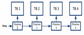
Connection diagrams for TV sockets
Connecting TV sockets according to the star pattern
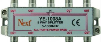
There is only one entrance to the apartment, but there are 2-3 TVs in a modern apartment. To connect two or more TVs, use a special splitter device - splitter , which has one input and 2-3-4 outputs. Then the connection diagram for TV sockets for televisions will be called star :
Connection diagram for TV antenna sockets with a star
It is assumed that the apartment is supplied with a cable with a cable television signal, in which the signal is quite strong. If you want to connect 2 or more TVs, it is better to ask your cable TV provider (or your neighbors) in advance whether the signal strength is enough. The signal level can be raised at your request; usually there is a resource for this. In addition, in some places you have to pay for connecting additional TVs, and for unauthorized additional connection you have to pay a fine.
If there are concerns that the power may not be enough, then it is necessary to provide space and power for installing a TV amplifier. It is indicated on the connection diagram with a star and a dash as an optional element. It is best to place the amplifier as close as possible to the signal source - at the entrance to the apartment or, better yet, at the television distribution panel in the entrance.
The “Star” scheme for connecting several TVs to one antenna is most widely used, as it has the following advantages:
- Cables to all sockets come out of one junction box, which is convenient for installation and maintenance,
- Minimum attenuation of the television signal,
- If one of the signal lines or sockets malfunctions, the rest operate normally.
The only downside is the high consumption of the antenna cable, which is insignificant, especially with optimal wiring. The peculiarity of this scheme is that the input and output cables should not lie next to each other so that there are no problems with signal quality.
Antenna splitter box. Antenna cable outputs for 3 TVs are at the top. On the side is the antenna input and, in the future, the Internet input. Everything is done with SAT 703 cable. Everything is then plastered, with only a cover on top for access to the splitter.
By the way, the same star connection scheme is used when wiring power supply circuits, and is the most preferable.
Connecting TV sockets using a pass-through design
This connection is also called a “ daisy chain ” connection diagram.
Connection diagram for TV antenna sockets with a cable
If the sockets are not shown with a star on the diagram, then they are required in the pass-through diagram. TV sockets in a daisy chain circuit must be used only through ones . The last socket in the daisy chain connection must be the terminal socket .
It is logical that the signal at the input of the first TV will be more powerful than the last one. But you don’t need to worry too much about this. The fact is that the cable television signal level is high enough to support all televisions. When using a high-quality television cable and the correct connection (F - connectors), the picture on the screens will be indistinguishable in quality.
In addition, modern televisions have a long-established amplification and automatic signal level control circuit.
Checking the functionality of the device
The TV cable is checked for the following reasons:
Check procedure:
- The power to the TV is turned off and all electrical wires are pulled out. If you are checking the cable of a collective antenna, then you need to check the serviceability of the tip located in the apartment. This circuit does not have a separator, and it is very difficult to access the other end of the wire.
- The resistance level is checked. Resistance is checked between the pin and ring outputs and the value should be at least 20 ohms. This error is created by an amplifier located in the electrical circuit. In the case of low voltage or its complete absence, the likelihood of a short circuit increases. These nuances mean that the cable is broken. A more reliable check is carried out if both ends of the cable are accessible.
- Connecting a resistance meter. First, disconnect the cord from all electrical appliances. Then the measuring element of the ohmmeter is connected to the main core and braid of the TV cable. The measuring device should show the value of infinity. After this, an ohmmeter is connected to the second end of the wire. The device readings should be close to zero.
- Visual assessment of the integrity of the television conductor. Testing is carried out for external deformations and damage. Next, an ohmmeter is connected at one end, and a jumper is placed at the other. If there is a short circuit, a jumper is not needed.
Such a cable is also checked by pressing it in some areas, and the resistance meter readings may change. After all defects have been eliminated, the jumpers are removed and the ohmmeter is turned off. The test is carried out by connecting the TV cable to the TV.
Connecting digital television (IPTV)
In addition to connecting to analogue television, many television providers now have the opportunity to connect to digital television. The quality there is much higher. Digital TV connection diagram - star only.
The fundamental differences are that a digital (computer) cable is used, a star connection; instead of a splitter, a digital splitter (router or hub) is used, which has one input and several outputs. One TV is connected to one output. The TV must understand the digital IPTV signal - have a CAM module. If your TV does not receive a digital TV signal, you need a special SD set-top box. In both cases, a smart card is purchased from the provider for charging and managing services.
Ask your provider if digital television (DVB) is the future. In apartment buildings in large cities, analog television will last a couple more years.
And the ethereal antennas have already died. Remember, 5-10 years ago all the windows, balconies and roofs of apartment buildings were covered with antennas?
Types of TV sockets
There are three types of television sockets: pass-through, terminal and single (simple).
Pass-through TV sockets have an input, an output (socket for connecting a TV) and another output to the next socket. Each pass-through socket introduces attenuation into the branch signal, which is approximately an order of magnitude greater than that of the end socket.
Final and simple TV socket - what's the difference?
In a star circuit, terminal or simple (single) TV sockets are used. There is no difference between them if a TV is connected to them. If the TV is not connected, then in the case of a simple socket, distortion of the image on the screen in the form of repetitions is possible. This happens because the terminal socket has a line impedance of 75 ohms. But a simple one does not have it, and the resistance in the line is equalized due to the input resistance of the connected TV. It does not matter at all whether the TV is connected to the 220 V power supply or not.
The terminal sockets are structurally designed to have a characteristic impedance equal to the characteristic impedance of the line, 75 Ohms.
What is the difference between an antenna cable
The structure of a television cable
To ensure a high-quality TV connection, in addition to choosing the right outlets, you should purchase a coaxial cable. Unlike a simple two- or three-core wire, such a cable uses a single core through which the television signal is transmitted, as well as a protective shield that protects the flow from the effects of electromagnetic fields on it.
Visually, it looks like a thick elastic wire with a round cross-section, which in most cases is surrounded by black or white PVC insulation. When installing the cable indoors, it makes no difference what color the external insulation is.
As an example, here are several of the most common types of cable that are used when laying wires under plaster or other types of finishing:
- RG-6 (also suitable for outdoor installation);
- SAT 50;
- RG-11.
Installation and connection of a TV outlet
The photo below shows how to connect a TV outlet with your own hands. In this case, this is the terminal socket. Step-by-step photos are provided; installation features depend on the specific design.
Installation boxes for antenna socket and 220V power socket
Installation boxes for antenna socket and 220V power socket. 220 socket installed
Preparing the TV cable before installing the socket
Preparing the TV cable before installing the antenna socket. 2nd stage of cleaning. The latch is pre-attached, but on the wrong side)
Preparing the TV cable before installing the TV socket. Third stage of cleaning
TV cable installation
Installing a TV cable - connecting a socket for a TV cable. Step 2
Installing a TV outlet - final installation of the cable. The black latch is now seated correctly
We carefully roll up the excess length of the cable without sharp bends. Could have left less.
That's it, all that remains is to put on the frame
Installing a TV outlet. Repeat of the photo shown at the beginning of this article
Below is another option for installing sockets for a TV. It’s clear that it’s better to hide everything behind the TV, isn’t it?
TV sockets - installation option
Optimal placement height
It is not always possible to calculate everything in advance when working with electrical wiring for a TV, especially since it can break and you will have to purchase another one, different in design from the previous one. Especially for such situations, a universal approach to choosing the height of the socket was developed.
According to this method, the optimal height of the outlet for your TV is about 130-140 centimeters from the floor. This data is usually used in rooms where TV viewing is done while sitting.
Where these numbers come from and how to independently calculate at what height to make a TV socket will be discussed below, and the formula used in the calculations will also be provided.
How to calculate the height of a TV outlet using the formula
The main criterion for the correct location of the TV outlet is the actual placement of the TV itself. At the same time, we must not forget that the TV should be located at a direct degree from the eyes of the viewer. If we take your view as a line, then the plane of the TV screen should be at an angle of 90 degrees to this imaginary line.
The location of the TV in the living room is recommended at a level of 120 centimeters from the floor. It is at this level that the eyes of a person sitting on a sofa or armchair are located.
In the image below you can see how to install the socket correctly: along the vertical axis, closer to the top edge of the case. The result was obtained using simple mathematical calculations.
The most popular diagonal of a modern TV is considered to be a 32-inch diagonal; the diagonal height of such a TV is about 40 centimeters. This is the smallest display, you don’t buy smaller ones, only bigger ones. For our calculations, we take the height of the TV, we take the height of the installed socket, which together with the plastic frame is 8 centimeters. Next we use the formula.
If the TV is located at a height of 120 centimeters from the floor, then the following solution is obtained: 120+40/2-8=132. All sizes are rounded for clarity.
If we use exact numbers in the formula, then as a result the socket will be 4 centimeters below the top edge of the display of the TV taken as an example, so it will not be noticeable even if you watch TV while standing.
Even without resorting to mathematics, you can install the socket at a height of 140 centimeters, in which case it will still be hidden by the TV body, and thanks to the adjustable brackets you can always slightly change the position and height of the TV.
The conclusion is as follows: if we know the parameters of the TV, we calculate everything using the formula; if we don’t know, we mount the outlet at a height of 140 centimeters from the floor.
In the image above you can see an excellent option for the location of the outlet: it is recessed into the wall. If your wall and the availability of the necessary tools allow this, this will be the best location. The height of the TV sockets will not cause you any difficulties.
| Friends, I would like to point out that when choosing the installation height of sockets for a TV, there are no clear norms or rules. In this matter, in each specific case an individual approach is needed, it all depends on the diagonal of the TV, the size of the furniture, the height of the ceilings, etc. This article provides only recommendations based on which you can make the right choice. |
Similar materials on the site:
- Where to place the light switch
- Should I leave the charger in the outlet?
- How to power the hood from an outlet
Antenna socket device
And finally - photographs of the terminal socket in disassembled form.
TV socket disassembled from the front
TV socket assembly rear view
TV socket disassembled rear view
That's all I wanted to tell you about installing TV outlets . If anything is not clear or you have something to add, ask and write in the comments. If you are interested in what I will publish next on the SamElectric blog, subscribe to receive new articles.
PS I consulted Legrand salespeople by phone about the difference between simple and terminal TV sockets. They said the following. “ Terminal sockets are used in conjunction with pass-through sockets, and simple sockets are used if with a splitter.” To be honest, I cannot confirm the information, since I have always installed only passing and end ones. And when asked about simple TV sockets, sellers look surprised and say that such things have never been on sale. All the better.
Installation of a socket box
Installing the socket into the glass begins with cutting out the recess. The depth depends on the type of socket box. If the outlet is a pass-through outlet, that is, other cables pass through it, then the depth should not exceed 7-8 cm.
In the case where the socket box is the final one, the recess should be no more than 5 cm
It is important to take into account during installation that the wires must lie freely in the housing. After all, a tightly bent cable can cause damage.
As a result, the entire structure will have to be disassembled and rebuilt.
Socket boxes are divided into two types:
- For drywall
- For hard stone
In the first version, the design of the socket box consists of a plastic body and metal latches on the sides. When secured to the drywall, the clamp fits into the groove, tightly holding the socket body. For reliability, the structure is secured with two dowels.
The second option is provided for stone or brick walls. In this case, the body is made of polycarbonate with two lugs on the sides. The socket body is fixed into the recess, which was previously hollowed out with a hammer drill.