Antenna
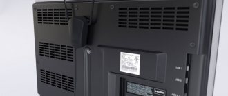
is a radio device designed to receive and emit electromagnetic waves through the air.
If you live within direct visibility of a television tower, then a simple homemade indoor television antenna, the design of which is presented in this article, is quite suitable for receiving digital television. This antenna is designed to receive television broadcasts in the digital television frequency range (470–790 MHz).
The design of a television antenna is simple and does not require special knowledge to repeat. To make it you will need 70 cm of copper wire with a diameter of 2-3 mm, a piece of double-sided fiberglass sheet, 1.5 m of coaxial television cable with a characteristic impedance of 75 Ohms and an F-plug.
Varieties
"Beer"
To make the product you will need an even number of beer cans. The most common options are made of two pieces. The installation process is quite simple and requires a minimum of tools and consumables.
Instructions:
- To begin with, take a wooden strip (a hanger will also do), which will serve as a support for the structure.
- Beer cans are attached to the rail using tape , at a distance of about 6 centimeters.
- Next, a television cable is attached to the banks. The procedure can be performed using either self-tapping screws or solder.
- The last step is to attach the base to the mast and adjust the position. A more complex version is made from 6-8 cans. Such an antenna will require two bases installed vertically.
- 4 cans are attached to the installed bases, parallel to each other.
- Using a copper plate or wire, you should connect the cans located on one rack, then perform the procedure on the other.
- The next step is to install the racks into one structure ; it should be taken into account that the distance between the bottoms of the cans must be at least 60 mm.
- It remains to secure the cable at the extreme points of the connecting plates.
Antenna with minimal costs
It should be remembered that television travels in space in the form of waves that are well perceived by metal objects. To watch several TV channels, you can use a piece of wire, one end of which is attached to the heating system, and the other into the TV to the central contact.
Read also: Optimal dimensions of a circular table
The principle of operation of such an antenna is based on the area of the system, and it envelops almost the entire house at different heights. The reception quality of the design is not the highest. A more interesting option requires a balcony with metal strings for laundry.
The assembly technology is completely similar to the battery system. There are places with reliable signal reception, where you can use a knitting needle, which will make it possible to view the main channels.
Regular antenna
Assembling the antenna yourself is quite simple; you will need a tube made of aluminum or brass. The latter option is more convenient, since this material practically does not oxidize.
Instructions:
- The length of the tubes should be 276 mm - this is what ensures the reception of most channels; the thickness is 20 mm. The tubes should be flattened on one side, then holes should be drilled in these places.
- The next stage is preparing the base. It must be made of dielectric material, measuring 150 by 50 mm and at least 5 mm thick.
- Next, a mock-up of the antenna is laid out on a flat surface. The base is laid, the tubes are placed on top of it, the distance between the flattened ends of the tubes is 65 mm, the locations of the holes in the tubes are marked and a hole is made in the base with a drill of the same diameter.
- The next stage is the assembly of the structure. The tubes are attached to the base using bolts; it is advisable to use an additional fastening in the form of a clamp - this will ensure the strength of the structure. The bolts used for fastening are 15-20 mm long, this is necessary for fastening the loop.
- The antenna assembly is complete , all that remains is to connect the cable; this cannot be done directly to the antenna. The correct connection is made through a ring of wire with a resistance of 75 ohms. The length of the loop is calculated individually depending on the length of the tube; in this situation it is 280 centimeters.
The outlet cable is already connected to the loop.
Powerful antenna
Having dealt with the classic options, you should consider antennas designed to receive the weakest signal. To create one, you will need a minimum of materials, namely a brass tube, a plate of the same material, desire and hands.
Instructions:
- The manufacture of the receiving device begins with bending two squares of the same size from the tube , attached to a dielectric base in such a way that the distance between the corners of the squares is 10-15 mm.
- The next step is making a screen designed to enhance the signal power and smooth out radio interference. The screen is curved in the shape of a rectangle 11x10 centimeters, with a side height of 23 mm and a width of 6 mm.
- When connecting two components, a distance of 12 mm must be maintained. The finished product is connected to the TV using a cable with a resistance of 75 Ohms. An important fact is that this design does not allow the use of bolted connections, only solder is allowed.
UHF antenna
Digital television is covering more and more territories, but for its reliable reception a special module is required. Often, the device is purchased separately, but there are TVs that have a built-in module.
But one receiver is not enough; you need an antenna that receives UHF waves. The simplest option is made on a sheet of plywood.
Instructions:
- For assembly you will need a 75 Ohm television cable 53 cm long. This section is fixed on a sheet in the shape of a ring; it can be secured either with clamps or with glue.
- When bending the loop, make sure that there is a gap of 5-10 mm between the ends of the cable. The second element of the product is made from a similar cable, 15.5 cm long, from which a loop is made.
- The connection between the ring and the loop is carried out as follows - the inner core of the ring is connected to the winding of both sides. The loop of the central conductor is attached to this twist, and the outer winding is connected between the edges. The central core of the antenna cable is connected to the inner core of the loop, and the winding is connected to the loop winding.
Instructions for making a UHF television antenna
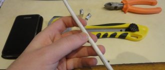
The first thing you need to do is select a piece of copper wire with a diameter of 2-3 mm and a length of 70 cm. For these purposes, a single-core copper wire is well suited for laying electrical wiring. If there are several conductors in the cable, then you need to carefully cut off one conductor along the groove, being careful not to damage the insulation. It is not needed for the antenna to work; the insulation is left only for aesthetic appearance.
An aluminum wire will also work, but then it will have to be connected to the contacts of the matching transformer board using a threaded connection. Please note that the nut should not touch the shielding foil of the transformer; if it does, then you need to lay an insulating washer or trim the foil.
If you use a wire without insulation, you can put a vinyl chloride tube on it for beauty.
Next, the wire needs to be bent into a ring with a diameter of approximately 220 mm. High precision is not needed here. A paint bucket holder or any other round container of suitable size works well for this.
When the antenna ring is ready, you can begin manufacturing the printed circuit board for the matching transformer.
The printed circuit board is made of fiberglass or getinax, foil-coated on both sides, 1.5 mm thick, 25x30 mm in size. The photo shows the appearance of the transformer printed circuit board on both sides.
This photo shows a negative of the antenna circuit board. The width of the current-carrying tracks is 1 mm, the distance between the tracks is 1.5 mm. Antenna board size 25×30 mm.
If it is not possible to make a printed circuit board for the manufacture of an antenna using a chemical method, then it can be made mechanically. To do this, you need to remove unnecessary sections of the foil, leaving only the contact pads, and lay out the current-carrying paths from copper wire with a diameter of 0.3-0.5 mm, gluing it to the board, for example, with “Moment” glue.
To give an aesthetic appearance and increase the mechanical strength of the antenna, the transformer is placed in a plastic box in which holes for the ring and antenna cable are pre-drilled.
When all the parts are prepared, you can begin assembling the antenna. The ends of the ring, pre-tinned with solder, are inserted into the box and bent at a right angle at a distance of 3 mm. Next, the ends are inserted into the printed circuit board of the antenna transformer and soldered with solder using a soldering iron.
The antenna board is placed on the bottom of the box and secured with an M3 screw and nut.
A television cable with a characteristic impedance of 75 Ohms, 1.5-1.8 m long, is threaded into the hole in the box. You can learn about choosing the type of cable, cutting it, and installing the F-connector from the article “Connecting a TV to an antenna cable.”
You first need to install a television F-connector on one end of it, and cut the other one and solder its ends onto a printed circuit board. The center core of the cable is soldered directly to the right end of the ring, and the braided shielding is soldered directly to the foil of the antenna board.
For reliable operation of the antenna, you need to solder or attach the cable in the following order. First, the shielding braid is soldered, then you need to pull the cable well to remove the slack, and only then solder the central core. In this case, when moving the antenna to find a place in the room with the maximum signal level and stretch the cable, the central core will not break.
If the cable screen is made of aluminum foil, then it can be pressed to the foil of the board using a metal clamp placed on a screw and secured with a nut. The technology for attaching the screen with a clamp is discussed in the article “How to make a TV crab with your own hands.”
All that remains is to close the box with a lid, insert the connector into the TV and tune the channels to the desired programs. In order to ensure image quality with minimal noise, you need to move the antenna around the room to find a place with the maximum television signal.
Settings
Installation of do-it-yourself products is carried out similarly to factory-made analogues. Most options require a mast to raise them to maximum height.
In most cases, a height of 2-3 meters higher than the height of the roof of the building is sufficient. Additionally, when installing, you should choose a place with the strongest signal, this is especially true for indoor devices.
Configuration is carried out by rearranging or rotating the antenna towards the tower; sometimes it is necessary to install an additional screen on the rear side.
Setting up TV channels
After the coaxial cable antenna is made, installed and connected to the TV, you can start setting up digital television.
Settings are performed differently on different brands of TVs. But the principle of searching for channels is the same everywhere. You need to go to the channel settings menu and perform an automatic or manual search.
Before setting up, be sure to go to the manual setup item and look at the signal level scale. If the signal is weak, try playing with the antenna, placing it in a different place, raising it higher, or changing the direction.
Example of a scale on a Samsung TV
For the most accurate direction of the structure to the nearest TV tower, use the terrestrial digital television map (karta.rtrs.rf). Enter your area and house number in the search bar. Click on your home and a table of repeater characteristics will appear. Look at the compass icon. When directing, be guided by it. This way you can receive the signal most accurately.
In most cases, automatic tuning of air channels will help. If the antenna shows only 10 channels out of 20, this may indicate the following:
- There is only one multiplex broadcasting in your area. This means you can only watch 10 channels.
- The signal is very weak, so only one of the channel packages (multiplexes) is caught. In this case, a more powerful antenna will help. Some options you can do yourself. But it’s better to take a closer look at factory antennas with a built-in amplifier.
After auto-search, if not all channels are shown, try searching manually. Then you need to find out the TVC (television channel) numbers or multiplex frequencies. All data is taken from the ECTV card.
Next, search for each multiplex one by one.
DIY amplifier
There are often situations when a properly assembled and well-tuned antenna refuses to reliably receive a signal, then you simply cannot do without a signal amplifier.
Most of these devices have a complex design, which is difficult to assemble without certain knowledge. A simpler version can be made with your own hands in 10 minutes.
You will need a magnet onto which several turns of television cable are wound. This device can be assembled either near the TV or on an antenna. The latter option is most popular in factory amplifiers.
Read also: Decoding the markings of steel R6M5
Results
Concluding the topic, you should pay attention to the fact that the highest quality of reception can be achieved by using soldering (bolts and nuts oxidize, significantly deteriorating the signal). An important aspect is the correct choice of cable. The most popular option is a product with a resistance of 75 Ohms, made of silicone.
Such products have a long service life, plus they are not affected by climate. The way you connect the cable to your TV is important. It is recommended to use special plugs; solderless options are allowed.
Before starting to assemble the product, you need to decide on the type of product; to do this, you should find out the frequency at which the signal is broadcast, this depends on the specific area.
Despite the rapid development of satellite and cable television, the reception of terrestrial television broadcasts still remains relevant, for example, for places of seasonal residence. It is not at all necessary to buy a finished product for this purpose; a home UHF antenna can be assembled with your own hands. Before moving on to considering the designs, we will briefly explain why this particular range of the television signal was chosen.
LiveInternetLiveInternet
MATCHING ANTENNAS In the preface to his book “Antennas,” Rothhammel repeated the well-known truth in the first line: a good antenna is the best high-frequency amplifier. However, many radio amateurs sometimes forget that building a good antenna system costs the same as a good transceiver, and setting up an antenna-feeder device requires the same serious approach as setting up a transceiver. Having built an antenna according to a description taken from somewhere, radio amateurs most often adjust it using an SWR meter, or generally rely on chance and do not make any measurements. Therefore, in many cases you can hear negative reviews about good antennas, or that they do not have enough authorized power for everyday communications. Here an attempt has been made to briefly review simple methods of matching and measurements in AFS (antenna-feeder systems) in the form of a guide to books (hereinafter referred to by number): K. Rothammel “Antennas”, M., “Energy”, 1979 third edition Z. Benkovsky, E. Lipinsky, “Amateur antennas of short and ultrashort waves”, M., “Radio and Communications”, 1983 and also provides some practical advice. So... Why can’t we take seriously the adjustment of newly created antenna-feeder devices using an SWR meter? The SWR meter shows the ratio (Udirect + Uref) to (Udirect-Uref) or in other words, how many times the impedance of the antenna-feeder path differs from the wave impedance of the device (transmitter output, for example). Based on the readings of the SWR meter, it is impossible to understand what SWR = 3 means when the output stage resistance is 50 Ohms. The characteristic impedance of the antenna-feeder path in this case can be purely active (at the resonance frequency) and can be equal to 150 Ohms or 17 Ohms (both are equally likely!). Not at the resonance frequency, the resistance will contain active and reactive (capacitive or inductive) in very different ratios, and then it is completely unclear what needs to be done - either to compensate for the reactivity, or to match the wave impedance. To accurately match the AFU, it is necessary to know: a) the real resonant frequency of the antenna; b) antenna resistance; c) characteristic impedance of the feeder; d) output impedance of the transceiver. The purpose of antenna matching is to satisfy two conditions for connecting the antenna to the transceiver: to ensure the absence of a reactive component in the antenna resistance at the frequency used. achieve equality of the wave impedance of the antenna and transmitting and receiving equipment. If these conditions are met at the point where the antenna is fed (the point where the antenna is connected to the feeder), then the feeder operates in traveling wave mode. If the matching conditions are met at the junction of the feeder with the transceiver, and the antenna impedance differs from the characteristic impedance of the feeder, then the feeder operates in a standing wave mode. However, operation of the feeder in standing wave mode may result in distortion of the radiation pattern in directional antennas (due to harmful radiation from the feeder) and in some cases may lead to interference with surrounding transceiver equipment. In addition, if the antenna is used for reception, then unwanted radiation (for example, interference from your desktop computer) will be received on the feeder braid. Therefore, it is preferable to use the antenna power supply via a feeder in traveling wave mode. Before sharing practical experience in antenna matching, a few words about the main measurement methods. 1. MEASUREMENT OF THE ANTENNA RESONANCE FREQUENCY 1.1. The simplest way to measure the resonant frequency of an antenna is using a heterodyne resonance indicator (HRI). However, in multi-element antenna systems, GIR measurements can be difficult or completely impossible to perform due to the mutual influence of the antenna elements, each of which may have its own resonant frequency. 1.2. Method of measurement using a measuring antenna and a control receiver. A generator is connected to the antenna being measured, and a control receiver with an antenna that does not have resonances at these frequencies (for example, shorter than l/10) is installed at a distance of 10-20l from the antenna being measured. The generator is adjusted in the selected part of the range, using the S-meter of the control receiver, the field strength is measured and the dependence of the field strength on frequency is plotted. The maximum corresponds to the resonance frequency. This method is especially applicable for multi-element antennas, in which case the measuring receiver must be located in the main lobe of the radiation pattern of the antenna being measured. A variant of this measurement method is to use it as a generator, a transmitter with a power of several watts and a simple field strength meter (for example [1], Fig. 14-20.). However, you must take into account that when taking measurements you will interfere with others. Practical advice for measurements in the range 144-430 MHz - when taking measurements, do not hold the field strength meter in your hands to reduce the influence of the body on the instrument readings. Fix the device above the floor at a height of 1-2 meters on a dielectric stand (for example, a tree, a chair) and take readings while being at a distance of 2-4 meters, without getting into the area between the device and the antenna being measured. 1.3. Measurement using a generator and an antennascope (for example [1], Fig. 14-16). This method is applicable mainly on HF and does not give accurate results, but it allows you to simultaneously evaluate the antenna resistance. The essence of the measurements is as follows. As you know, an antennascope allows you to measure impedance (active + reactive). Because antennas are usually powered at the current antinode (minimum input resistance) and there is no reactivity at the resonance frequency, then at the resonance frequency the antennascope will show minimal resistance, and at all other frequencies it will most often be greater. Hence the sequence of measurements - by rebuilding the generator, they measure the input impedance of the antenna. The minimum resistance corresponds to the resonant frequency. One BUT - the antenna scope must be connected directly to the antenna feed point, and not through a cable! And a practical observation - if there is a powerful source of radio emission near you (television or radio station), due to interference, the antenna scope will never balance “to zero” and it becomes almost impossible to take measurements. 1.4. It is very convenient to determine the resonant frequency of vibrators using an frequency response meter. By connecting the output of the frequency response meter and the detector head to the antenna, the frequencies at which dips in the frequency response are visible are determined. At these frequencies, the antenna resonates and energy is taken from the output of the device, which is clearly visible on the device screen. Almost any frequency response meters are suitable for measurements (X1-47, X1-50, X1-42, SK4-59). Measurement option - using a spectrum analyzer (SK4-60) in long-persistence mode and an external generator. You can use a harmonic generator as an external generator: at HF - with a step of 10 kHz, at 144 MHz - with a step of 100 kHz, at 430 MHz - with a step of 1 MHz. At frequencies up to 160 MHz, the most uniform spectrum with high harmonic intensity is provided by the harmonic generator circuit on the 155IE1 integrated circuit. In the 430 MHz range, a sufficient level of harmonics can be obtained in a circuit with a 2A609B storage diode (50 MHz calibrator circuit from SK4-60). 2. MEASUREMENT OF RESISTANCE IN ANTENNA-FEEDER DEVICES. 2.1. The simplest (still affordable) commercially produced device for measuring active resistance and signal phase (and therefore the reactive component) is a measuring bridge. There are several modifications of these devices for use with 50 and 75 ohm paths and for various frequency ranges up to 1000 MHz - these are measuring bridges R2-33...R2-35. 2.2 In amateur radio practice, a simpler version of the measuring bridge designed for impedance measurements (antennascope) is more often used. Its design, unlike the P2-33 bridges... is very simple and can be easily repeated at home ([1], pp. 308-309). 2.3 It is useful to remember some notes regarding resistances in APS. 2.3.1. A long line with characteristic impedance Ztr and electrical length l/4, 3 x l/4, etc. transforms the resistance, which can be calculated from the formula Ztr=Sqr(ZinZout) or according to Fig. 2.39 [2]. In a particular case, if one end of the l/4 segment is open, then the infinite resistance at this end of the segment is transformed into zero at the opposite end (short circuit) and such devices are used to transform large resistances into small ones. Attention! These types of transformers operate effectively only in a narrow frequency range, limited to fractions of a percent of the operating frequency. A long line with an electrical length that is a multiple of l/2, regardless of the wave impedance of this line, transforms the input impedance into the output impedance with a ratio of 1:1 and they are used to transmit resistances to the required distance without transforming the resistances, or to reverse the phase by 180°. Unlike l/4 lines, l/2 lines have greater bandwidth. 2.3.2. If the antenna is shorter than you need, then at your frequency the antenna resistance has a reactive component of a capacitive nature. In the case where the antenna is longer, at your frequency the antenna has an inductive reactance. Of course, at your frequency, unwanted reactivity can be compensated for by introducing additional reactivity of the opposite sign. For example, if the antenna is longer than necessary, the inductive component can be compensated by connecting a capacitor in series with the antenna power supply. The value of the required capacitor can be calculated for the required frequency, knowing the value of the inductive component (see Fig. 2.38 [2]), or selected experimentally, as described in paragraph 5. 2.3.3. The introduction of additional passive elements usually reduces the input impedance of the antenna (for example, for a square: from 110-120 Ohms to 45-75 Ohms). 2.3.4. Below are the theoretical values of the most common vibrators (vibrators are located in a space free from surrounding objects), antennas and feeders: half-wave vibrator with power supply at the current antinode (in the middle) - 70 Ohms, with a detuning of +-2% the reactance of iX changes almost linearly from -25 to +25 with zero at the resonance frequency; half-wave vibrator powered using a T-shaped matching circuit -120 Ohm; - a loop vibrator with the same diameters of all conductors - 240..280 Ohm, with a detuning of +-1% there is no reactance, but with detunings of more than 2%, the reactance iX sharply increases to +- 50 or more (see Fig. 2.93 [2] ); loop vibrator with different conductor diameters (see table 1.15 [1] or Fig. 2.90c [1]) - up to 840 Ohm; — double loop vibrator with the same diameters of all conductors — 540...630 Ohm; double loop vibrator with different conductor diameters (see table 1.16 [1] or Fig. 2.91 [2]) - up to 1500 Ohm; quarter-wave vertical vibrator with counterweights at an angle of 135° relative to the vibrator - 50 Ohm; quarter-wave vertical vibrator with counterweights at an angle of 90° relative to the vibrator - 30 Ohm; vibrator in the form of a square with a length l - 110..120 Ohm; — vibrator in the form of a square 2l long (two turns) — 280 Ohm; vibrator in the form of a triangle (delta) - 120...130 Ohm; Inverded-V with an opening angle of 90° - 45 Ohms; Inverted-V with an opening angle of 130° - 65 Ohms; wave channel optimized for maximum gain - 5...20 Ohms; wave channel optimized for the best matching - 50 Ohms; two-wire line (Fig. 2.26 [2]) - 200..320; two parallel coaxial lines Z=75 Ohm - 37.5 Ohm; the same, quarter-wave transformer Zin=50 Ohm - Zout=28 Ohm; the same, quarter-wave transformer Zin = 75 Ohm - Zout = 19 Ohm; two parallel coaxial lines Z=50 Ohm - 25 Ohm; the same, quarter-wave transformer Zin=50 Ohm - Zout=12.5 Ohm; the same, quarter-wave transformer Zin=75 Ohm - Zout=8.4 Ohm transformer of three parallel lines Z=50 Ohm Zin=50 - Zout=5.6 Ohm; the same Z=50 Ohm Zin=75 - Zout=3.7 Ohm; 3. MEASUREMENT OF THE DEGREE OF CORRESPONDENCE It is advisable to do these measurements after the coordination described in paragraph 5 to assess the quality of the coordination. 3.1. Instruments for determining the degree of matching of open two-wire lines with an antenna: 3.1.1. An ordinary neon light bulb or GIR. When moving the light bulb along the transmission line, the brightness of the light bulb should not change (travelling wave mode). The measurement option is a device consisting of a communication loop, a detector and a dial indicator (see Fig. 14.8 [1]). 3.1.2. Two-lamp indicator (see Fig. 14.7 [1]). By adjusting the settings, you ensure that the light bulb connected to the arm close to the antenna does not glow, and in the opposite arm the glow is maximum. At low power levels, you can use a detector and dial indicator instead of a light bulb. 3.2. Instruments for determining the degree of matching in coaxial paths: 3.2.1. A measuring line is a device that is applicable for measuring the degree of matching in coaxial and waveguide lines from VHF to the centimeter wave range. Its design is simple - a rigid coaxial cable (waveguide) with a longitudinal slot in the outer conductor, along which a measuring head moves with a measuring probe lowered into the slot. By moving the measuring head along the path, the maximum and minimum readings are determined, the ratio of which is used to judge the degree of agreement (travelling wave mode - the readings do not change along the entire length of the measuring line). 3.2.2. Measuring bridge (Fig. 14.18 [1]). Allows you to measure SWR in transmission lines up to 100 Ohms on HF and VHF with an input power of about hundreds of milliwatts. The design is very simple to manufacture; it does not contain skein catches or structural units that are critical to manufacturing accuracy. 3.2.3. SWR meters based on reflectometers. Many designs of these devices are described (for example, Fig. 14-14 [1]. They allow you to monitor the state of the APS during operation on the air. 3.2.4. SWR meters based on frequency response meters. Very convenient for studying the quality of matching at any frequency, up to up to 40 GHz. Measuring principle - the measuring set of devices consists of an frequency response meter and a directional coupler, connected in the following circuit: 1 X1-47>———————>3 2<———————<1 3 Directional coupler 2><——————-|/ Ant.4 where 1 - frequency response meter (X1-47); 2 - low-impedance detector head from the X1-47 kit; 3 - directional coupler, for example, for the 144 MHz range, NO 991 is suitable -03 from the kit for the SK4-60 device; 4 - antenna to be measured. The high-frequency signal from output X1-47 goes to pin 3 of the directional coupler and then goes only to pin 2 of the directional coupler. Then the signal is transmitted to the antenna being measured. At frequencies where the antenna has a high SWR, the energy is reflected and returned to pin 2 of the directional coupler. In this signal direction, energy is transferred from pin 2 only to pin 1, is detected by the detector head and the level of the reflected signal is displayed on the screen X1-47 depending on the frequency. Before starting measurements, it is necessary to calibrate the circuit. To do this, instead of the antenna being measured, connect a non-inductive equivalent of an antenna with a resistance of 50 Ohms and make sure that there is no reflected signal (SWR = 1). Next, having undocked the equivalent, note the signal level for SWR = infinity. All intermediate SWR values will be displayed on the device screen in a position between 0 and the maximum value. When connecting equivalent antennas with resistances of 75 Ohm, 100 Ohm, 150 Ohm, the SWR values are marked on the device screen as 1.5, 2, 3, respectively. As an AFC meter, you can use the SK4-60 spectrum analyzer and an external generator, depending on the wave range in which the measurements are made (G4-151 up to 500 MHz, G4-76 up to 1.3 GHz, G4-82 5.6 GHz, G4-84 10 GHz). At frequencies up to 500 MHz, harmonic generators described in paragraph 1.4 can be used as an external generator. Two notes: directional couplers introduce about 15 dB of transient attenuation to the signal source, so measurements require fairly high-level signal sources; The directional properties of the couplers (isolation and directivity) usually do not exceed 20...30 dB, so measurements must be performed not on a logarithmic, but on a linear display scale. 4. SOME USEFUL METHODS OF MEASUREMENT. 4.1. Measurements using an antennascope (given in [1] pp. 308-312). 4.1.1. Determining the exact electrical length l/4 of the line: for this, the line is connected at one end to the antennascope, and the other is left open. Next, by changing the frequency of the generator, the lowest frequency is determined at which the balance of the bridge is achieved at zero resistance. For this frequency the electrical length of the line is exactly l/4. 4.1.2. Measuring the wave impedance of the line Ztr: having carried out the measurements according to clause 4.1.1., connect a 100 Ohm resistor to the free end of the line and measure the resistance Zmeas at the other end of the line with an antenna scope. Calculate the characteristic impedance of the line using the formula Ztr=Sqr(100xZmeas) 4.1.3. Checking the accuracy of the dimensions l/2 of the transforming line: the measured line is connected to the antenoscope, a 300 Ohm resistor is connected to the second end of the line. The generator sets the frequency at which the l/2 line should transform 1:1. The resistance is measured with an antennenic-scrap- it should be 300 Ohms if the line is precisely equal to L/2 for this frequency. 4.1.4. Determination of the shortening coefficient of the transmission line: for measurements, a line of the line is a few meters long (length X). Cloth one end of the line and, changing the generator frequency, find the minimum frequency value of F, at which the antennoscope is balanced, this will mean that the line transformers the resistance of 1: 1 and for this chatota its electric length corresponds to L/2, taking into account the shortening coefficient. By increasing the frequency, it will be possible to find the next balance of the bridge corresponding to 2 l/2, etc. L/2 length for the frequency l = 300/(2F), and the shortening coefficient k = x/l. For example, if the line length is x = 3.3 meters, and the balance occurred at a frequency F = 30 MHz, then l = 5 meters, and k = 0.66. The usual values of shortening coefficients for coaxial lines are 0.66, for tape cables - 0.82, for open two -wire lines - 0.95. 4.2. Measurements using the frequency response-meter are made according to the scheme given in P3.2.4. 4.2.1. Localization of heterogeneity in a feeder. If necessary, determine the distance to heterogeneity in a feeder (short circuit or cliff) without dismantling the feeder, this can be done as follows. With a break or short circuit in a feeder, the maximum KSV will be observed at frequencies where the line works as a L/2 transformer, as well as at multiple frequencies, regardless of the range selected for measurements. The feeder is plowed from the transceiver and connected to the output 2 of the directed branch. They set up such a rocing strip so that it is convenient to measure the period of the SCS. The measured period in the megagers corresponds to the frequency at which the line works as L/2, taking into account shortening. Suppose a frequency interval between the maximums of the KSV is 3 MHz, which means that the frequency on which the line now works as a transformer L/2, equal to 6 MHz and this will correspond to a wavelength of 50 meters (i.e. to a heterogeneity of 50 meters, excluding the line of shortening of the line). Knowing the coefficient of shortening the line, one can accurately say the actual distance to heterogeneity. For example, if the line is made by a coaxial cable with a coeff. shortening 0.66, then in our case, the distance from the gear to the cliff (KZ) in the CACSOL cable is 33 meters. 4.2.2. Measurement of the cable shortening coefficient. Measurements are made in the same way as in paragraph 4.2.1. , but to the conclusion 2 of the directed branch, the measured cable several meters long is connected. Suppose we measure the coefficient of shortening of a cable 33 meters long. The measured electric length of the cable is 50 meters, so the shortening coefficient is 33/50 = 0.66. 4.2.3. Checking the cable 50 ohms for the lack of heterogeneity. To the conclusion 2 but connect the checked cable, on the other end of which the coordinated load 50 Ohms is connected. A flat line should be observed on the device’s screen if there are no heterogeneities in the cable. 5. The procedure for setting up the antenna as an example, a few words about the procedure for setting up the delta antenna for the range of 80 meters, using the measurement methods given above. It is necessary to coordinate the output cascade of the transmitter (50 Ohm) with an antenna in a cable of 50 Ohms. If there is no way to measure the resistance of the antenna and find the resonant frequency of the antenna, connecting directly at the recording point, we connect the transforming L/2 line between the devices and the antenna. Thus, using the transforming properties of the line (1: 1), measurements can be carried out not directly at the antenna, but on the other end of the line. One of the described methods, we measure the resistance of the antenna and the resonant frequency. If the resonance frequency of the antenna is slightly displaced, a change in the geometric size of the antenna, achieve resonance at the desired frequency. Typically, the resistance of the delta antenna is 120 Ohms and to coordinate the antenna with the cable, it is necessary to apply a transformer 1: 2.4. This transformer can be done using a three-wirewater with the ratio of RVI/RVX = 4/9 (Bunin, Tiring Radio Amateur Radio-Morror-Wilm, Kyiv, Technique). After manufacturing the transformer, the resistor with a resistance of 120-130 Ohms is connected to the high-resistant input of the transformer and, by connecting the antennocrax to another input, measure its input resistance and transformation coefficient. By connecting the transformer between the PA and the power line, the current in the antenna is checked using the PF-ammeter (Fig. 14-2 [1]). It is better to measure the current after PA using a calibrated HF ammeter and calculate the absorbed power. If after calculation it turns out that P = RII is less than on the equivalent of the antenna, then the coordinating device makes reactivity and it must be compensated. For this, a variable capacitor (10-500 PF) and changing its value are included in series with HF ammeter, the maximum is achieved in the readings of the RF-ammeter. In the event that using the capacitor, it is not possible to increase the current in the antenna, you need to replace the capacitor with a variometer and choose a compensating inductance. After selecting compensating reactivity, it is measured and replaced by an element with a constant value. After setting up the coordinating device, it is placed in a sealed housing and transferred to the antenna signature point from the cable. In conclusion, the approval is once again checked using one of the methods of measuring the CSV. Computer connection tips. Many complain that their desktop computer greatly interferes with the reception. The reason for this in most cases is the poor coordination of the antenna. In this case, the braid of the antenna cable takes the computer radiation and they in the form of interference fall into the input of the receiver. It is simple to check this assumption- to unsubscribe the cable from the entry of the receiver, if the interference disappears, then the main path of interference from the computer to the input of the receiver is on the cable brand. After careful coordination of the antenna using the methods below, you can largely get rid of interference at the reception and from the unstable operation of digital nodes during transmission. The second necessary condition for the convenience of working with a computer is a thorough grounding of all devices. Grounding on a heating pipe - not good! The third way is to enclose all cables going from the computer into the screen and it is very desirable to let each of them through the ferrite ring 2000 nm (pair of turns). You can also skip through the ring and the antenna cable (for additional symmething of the cable and eliminate the spread of HF signals for cable braid). Sometimes the source of interference is a monitor and cables going to it. Try to turn on, turn off the monitor from the network when the computer operating and loading. If the level of interference changes, it is recommended to separately ground the monitor chassis, and the landing point of the chassis must be selected experimentally at a minimum of interference.
Indoor TV antenna “Rhombus”
This simple, but at the same time, reliable design was one of the most common in the heyday of on-air television broadcasting.
Rice. 1. The simplest homemade Z-antenna, known under the names: “Rhombus”, “Square” and “People’s Zigzag”
As can be seen from the sketch (B Fig. 1), the device is a simplified version of the classic zigzag (Z-design). To increase sensitivity, it is recommended to equip it with capacitive inserts (“1” and “2”), as well as a reflector (“A” in Fig. 1). If the signal level is quite acceptable, this is not necessary.
The material you can use is aluminum, copper, and brass tubes or strips 10-15 mm wide. If you plan to install the structure outdoors, it is better to abandon aluminum, since it is susceptible to corrosion. Capacitive inserts are made of foil, tin or metal mesh. After installation, they are soldered along the circuit.
The cable is laid as shown in the figure, namely: it did not have sharp bends and did not leave the side insert.
Antenna matching and matching devices
In amateur practice, it is extremely rare to use antennas whose input impedance is equal to the wave impedance of the feeder, and in turn, the output impedance of the transmitter (ideal matching option). Most often, there is no such correspondence and special matching devices have to be used. The antenna, feeder and transmitter output should be considered as a single system in which energy must be transmitted without loss.
The implementation of this difficult task will require coordination in two places: at the point of connection of the antenna with the feeder and the feeder with the transmitter output. The most popular are various types of transforming devices: from resonant oscillatory circuits to coaxial transformers in the form of sections of coaxial cable of the required length. All of them are needed to match resistances, which ultimately leads to minimizing losses in the transmission line. And, most importantly, to reduce out-of-band emissions.
As a rule, the standard output impedance of modern broadband transmitters (transceivers) is 500m. Most coaxial cables used as feeders also have a standard impedance value of 50 or 750 m. Antennas, depending on the type and design, can have an input impedance in a very wide range of values: from several Ohms to hundreds of Ohms and more. It is known that the input impedance of single-element antennas at the resonant frequency is practically active. And the more the transmitter frequency differs from the resonant* frequency of the antenna in one direction or another, the more a reactive component of a capacitive or inductive nature appears in the input impedance of the antenna. In multi-element antennas, the input impedance at the resonant frequency is complex, since passive elements contribute to the formation of the reactive component.
In the case when the input impedance of the antenna is purely active, it is not difficult to match it with the feeder impedance using any of the suitable transforming devices. At the same time, the losses are quite insignificant. But, as soon as a reactive component is formed in the input resistance, the matching becomes more complicated, and a more complex matching device is required that can compensate for the unwanted reactivity. And this device must be located at the antenna feed point. Uncompensated reactance worsens the SWR in the feeder and increases losses. An attempt to fully compensate for reactivity at the lower end of the feeder (at the transmitter) is unsuccessful, since it is limited by the parameters of the feeder itself. Tuning the transmitter frequency within narrow sections of the amateur bands does not lead to the appearance of a significant reactive component, so in most cases there is no need to compensate for reactance. Properly designed multi-element antennas also do not have much input reactance and usually do not need to compensate for it.
On the air, disputes often arise about the role and purpose of the antenna matching device (antenna tuner) when matching the transmitter with the antenna. Some have high hopes for it, others consider it an unnecessary toy. What actually (in practice) can and cannot help an antenna tuner?
First of all, a tuner is a high-frequency impedance transformer that can, if necessary, compensate for reactance of a capacitive or inductive nature.
Let's consider a simple example: A split vibrator (dipole), which has an active input impedance of about 700 m at the resonant frequency, is connected by a 75-ohm coaxial cable (feeder) to a transmitter whose output impedance is 500 m. The tuner is installed at the output of the transmitter and in this case acts as a matching unit between the feeder and the transmitter, which it easily copes with. If the transmitter is tuned to a frequency different from the resonant frequency of the antenna, then reactivity will arise in the input impedance of the antenna, which will immediately appear at the lower end of the feeder. The tuner is also able to compensate for it, and the transmitter will again be matched to the antenna feeder.
What will happen at the output of the feeder, at the point of its connection to the antenna? Using a tuner only at the transmitter output, full compensation will not be possible, and losses will occur in the feeder due to inaccurate matching with the antenna. In this case, you will need another tuner, which will have to be connected between the feeder and the antenna, then it will correct the situation and compensate for the reactivity. In this example, the feeder acts as a matched transmission line of arbitrary length.
Another example: A loop antenna having an input impedance of approximately 1100 m must be matched to a 50 ohm transmission line. Transmitter output 500m. Here you will need a matching device installed at the point where the feeder is connected to the antenna. Typically, many hobbyists use various types of RF transformers with ferrite cores, but it is more convenient to make a quarter-wave coaxial transformer from a 75-ohm cable. The length of the cable section is A/4 x 0.66, where R is the wavelength, 0.66 is the shortening factor for most known coaxial cables. A coaxial transformer is connected between the antenna input and the 50 ohm feeder. If it is rolled into a coil with a diameter of 15...20 cm, then it will also serve as a balancing device. The feeder and transmitter are automatically matched when their resistances are equal. In this case, you can refuse the services of an antenna tuner altogether.
For this example, another matching method is possible: Using a half-wave or half-wave coaxial cable with any characteristic impedance (also taking into account the shortening factor). It is connected between the antenna and the tuner located near the transmitter. The antenna input impedance of about 110 Ohms is transferred to the lower end of the cable and, using the tuner, is transformed into a resistance of 500 m. In this case, there is complete coordination of the antenna with the transmitter, and the feeder acts as a repeater.
In more complex cases, when the input impedance of the antenna does not match the characteristic impedance of the feeder, and the impedance of the feeder does not match the output impedance of the transmitter, two matching devices are needed. One at the top for matching the antenna with the feeder, the other at the bottom for matching the feeder with the transmitter. And it is not possible to get by with just one antenna feeder to coordinate the entire chain: antenna - feeder - transmitter.
The presence of reactivity further complicates the situation. The antenna tuner in this case will significantly improve the matching of the transmitter with the feeder, thereby facilitating the operation of the final stage, but nothing more. Due to mismatch between the feeder and the antenna, losses will occur, and the efficiency of the antenna itself will be reduced. The switched on SWR meter between the transmitter and the tuner will record SWR=1, but this will not happen between the tuner and the feeder due to the mismatch between the feeder and the antenna.
A completely fair conclusion arises: the tuner is useful in that it supports the normal mode of the transmitter when operating on an unmatched load, but at the same time it is not able to improve the efficiency of the antenna when it is mismatched with the feeder.
The P-circuit used in the output stage of the transmitter can also serve as an antenna tuner, but subject to prompt changes in inductance and both capacitances. As a rule, antenna tuners, both manual and automatic, are resonant loop tunable devices. Manual ones have two or three regulating elements and are not efficient in operation. Automatic ones are expensive, and for high-power operation they are very expensive.
Let's look at a fairly simple broadband matching device (tuner) in Fig. 1, which satisfies most variations in matching the transmitter to the antenna. :
It is very effective when working with antennas (loops, dipoles) used on harmonics when the feeder is a half-wave repeater. In this case, the input impedance of the antenna is different on different bands, but with the help of a matching device it is easily matched to the transmitter. The proposed tuner can operate at transmitter powers up to 1.5 kW in the frequency band from 1.5 to 30 MHz. The main elements of the tuner are an RF autotransformer on a ferrite ring from the deflection system of the UNT-35 TV and a 17-position switch. It is possible to use conical rings from TVs UNT-47/59 or others.
The winding contains 12 turns wound into two wires. The beginning of one winding is connected to the end of the other. In the table and diagram the numbering of turns is continuous. The wire itself is stranded with fluoroplastic insulation. Wire diameter 2.5mm insulation. Taps are made from each turn, starting from the eighth from the grounded end.
The switch is ceramic, biscuit type with 17 positions.
The autotransformer is located as close as possible to the switch, and the connecting conductors between them must be of a minimum length. It is possible to use a switch with 11 positions while maintaining the design of the transformer with fewer taps, for example, from 10 to 20 turns. But in this case, the resistance transformation interval will also decrease.
Knowing the input impedance of the antenna, you can use such a transformer to match the antenna with a 50 or 750 m feeder, making only the necessary taps. In this case, it is placed in a moisture-proof box, filled with paraffin and installed at the antenna feed point.
Also, this matching device can be made as an independent structure or be part of the antenna-switching unit of the radio station.
For clarity, the mark on the switch handle (on the front panel) indicates the resistance value corresponding to this position. To compensate for the reactive component of an inductive nature, it is possible to connect a variable capacitor C1, Fig. 2.
The dependence of the resistance on the number of turns is given in Table 1. The calculation was made based on the resistance ratio, which is a quadratic function of the number of turns.
Table 1.
RELATED ARTICLES ON THE TOPIC:
- Multiband Inverted L Antenna “Inverted L” antenna made from antenna cable. To increase operating efficiency, it is advisable to place its vertical part as high as possible. Such an antenna receives electromagnetic radiation with both vertical and horizontal polarization, so when working on it, the fading that accompanies HF reception should apparently appear less than...
- Antennas. Urban Designs The book discusses antennas that radio amateurs can install in urban environments. Practical antenna designs are presented for all amateur radio HF bands, the MF band of 27 MHz and for the VHF band of 144 MHz, and the method for setting them up is described. Theoretical information is given to the minimum extent necessary for the construction of the described antennas. Book…
- Antennas and their configuration Many do not understand the importance of good coordination of the Radio-Transmission Line-Antenna path. Or rather, they understand the importance, but are completely unable to really assess the state of affairs. Most often, they are content with readings of the built-in SWR meter close to unity. The most unpleasant thing about this is that if the situation is bad, the owner...
- Simple antennas for the 160 m range A simple and effective antenna for the 160 m range is the dream of almost every radio amateur, especially an inveterate “DX hunter”. How can you start working in this range without large technical and material costs? After all, the 160 m range places increased demands on both the skills of a radio amateur on the air,...
- 50 MHz Antenna A simple directional antenna for the 50 MHz band was designed by Robert Snary, G40BE. This type of antenna was proposed for the first time by VK2ABQ for the HF ranges of 14, 21 and 28 MHz due to their greater broadband compared to “squares” and “Yagi”….
- Matching antenna transformer 1:4 (balun) from DGOSA The balun is made on a ferrite toroidal core FT140-43 (ferrite rings 400-600NN with a size of about 35.55 × 23.0 × 12.7 mm can be used). On both halves of this core, two windings of 12 turns are wound with a symmetrical LFL line with a characteristic impedance of 100 Ohms...
- Effective CB band antenna A vertical antenna of 5/8 wavelength plus a quarter-wave cable connected in parallel produces a very simple and effective stationary antenna system for long-distance radio communications on the 27 MHz band….
- Multi-band attic antenna from MM0YEC In distant Scotland, among the hills and moors, there is a small town of Fife, where radio amateur Christoph Echtermeyer, MMOYEC, lives. His radio station is located in a cozy cottage, which is so pleasant in the autumn storm, and in the harsh winter it is well warmed by a fireplace and a glass of good old malt whiskey. Primordial...
UHF antenna with amplifier
In places where a powerful relay tower is not located in relative proximity, you can raise the signal level to an acceptable value using an amplifier. Below is a schematic diagram of a device that can be used with almost any antenna.
Rice. 2. Antenna amplifier circuit for the UHF range
List of elements:
- Resistors: R1 – 150 kOhm; R2 – 1 kOhm; R3 – 680 Ohm; R4 – 75 kOhm.
- Capacitors: C1 – 3.3 pF; C2 – 15 pF; C3 – 6800 pF; C4, C5, C6 – 100 pF.
- Transistors: VT1, VT2 – GT311D (can be replaced with: KT3101, KT3115 and KT3132).
Inductance: L1 – is a frameless coil with a diameter of 4 mm, wound with copper wire Ø 0.8 mm (2.5 turns must be made); L2 and L3 are high-frequency chokes 25 µH and 100 µH, respectively.
If the circuit is assembled correctly, we will get an amplifier with the following characteristics:
- bandwidth from 470 to 790 MHz;
- gain and noise factors – 30 and 3 dB, respectively;
- the value of the output and input resistance of the device corresponds to the RG6 cable – 75 Ohm;
- the device consumes about 12-14 mA.
Let's pay attention to the method of power supply; it is carried out directly through the cable.
This amplifier can work with the simplest designs made from improvised means.
What you need to assemble a digital antenna
How to make your own antenna for digital TV? The main condition for self-assembly of a digital antenna is the use of a wire or tube (copper or aluminum) with a diameter of 3 mm (sectional area slightly less than 6 mm2).
It is not always possible to find such material even in specialized hardware and electrical stores.
Therefore, from a huge variety of types of homemade antennas, we chose the most optimal and least expensive - using the antenna wire itself as the main material.
When choosing such a cable in a store, you must proceed from the parameters that it must have a characteristic impedance of 75 Ohms, and its cross-section (including the sheath) must be at least 6 mm.
It is highly desirable that the central core and shielding braid be copper. Antenna cables with a copper-plated steel center wire are commercially available.
This is a budget option and is not very desirable to use.
The antenna itself will require a cable length of about 2 m in total, and to connect to your TV you need to determine the required distance yourself.
In addition to the antenna cable itself, you will need:
- soldering iron with solder and rosin;
- sharp knife with short blade
- pliers with wire cutter function and electrical tape
- sealant or glue gun with the appropriate consumable plastic rods (if you are going to place the antenna outside).
Antenna design features
Most antennas offered on the Internet have an angular design made of copper or aluminum tubes (or thick wires), which works great in open areas with direct visibility of the translator. Another type is based on a circle of antenna cable.
Both designs do not provide very good reception in dense urban areas or in places closed from the line of sight of the translator.
Our version of the antenna (seen on a popular video hosting site) is focused on both the direct signal and the one reflected from buildings in the city. That is why the design consists of two concentric rings made of antenna cable, which greatly simplifies its manufacture.
This might be interesting:
How to make an antenna for digital television with your own hands: step-by-step instructions
Before we start cutting and stripping the wire, we need to determine the correct length of cable sections for the components of our antenna. To do this, you need to find out the digital television broadcast frequency in your area. But how to calculate an antenna for digital TV? Go to the official website map.rtrs.rf and find your area of residence.
In the left menu, select the “Frequency zones” checkbox. Now, in addition to frequency ranges, the map will display multiplex packages and indicate the number of channels included in them.
For example, throughout almost the entire Moscow region, the I-multiplex (RTRS-1) includes 10 channels (they are broadcast on channel 30) and can be caught at a frequency of 546 MHz; the II-multiplex (RTRS-2) also includes 10 channels and is broadcast they are on channel 24 at 498 MHz.
To calculate the length of cable sections for an antenna based on frequency maps, you need to use the formula for determining the wavelength:
λ=300/F , where F is the frequency of the transmitted signal in MHz.
For example, for a frequency of 546 MHz the wavelength is about 550 mm . It is this length of cable that should be used to obtain the first circle of the antenna.
To receive the second multiplex with a frequency of 498 MHz, the length of the antenna cable must be about 600 mm .
The first step is to cut the cable into the required lengths. In our case it is 550 and 600 mm. After this, each end of the cable is freed by 15 mm from the outer braid, and the shielding is twisted into a tight pigtail and tinned with a soldering iron. Leave the central part of the wire untouched in the braid. She won't be needed.
The second step is to solder the right end of the tinned shield pigtail of one wire to the other, then do the same with the left ends of the cable. Do not touch the central wires of the antenna cable. You can even wrap them with electrical tape to prevent the ends from touching each other.
Thus, the base of our concentric antenna is made.
The third step is to roll both segments into rings and place them concentrically, i.e. one ring inside the other, for example, on a cardboard from under shoes and secure closer to the ends with packing wires.
The only thing left to do is connect the antenna cable leading to your TV and insulate the exposed contacts.
Fourth step - take your antenna cable of the required length, strip both ends of it from the outer braid by about 15 mm. Clean the end of the cable leading to the antenna in a special way: twist the shielding cable braid into a tight braid and tin it.
And strip the central wire of the remaining braid by 10 mm, leaving about 5 mm of braid to protect it from a short circuit with the screen wire.
Fifth step - bring the antenna cable with prepared ends to the previously obtained antenna from concentric rings and twist the end of the braid from it with the end from the left side of the antenna, solder the resulting connection.
The sixth step is to insulate the exposed wires. For these purposes, you can use electrical tape or a glue gun (if you have one). Twist the second wire - the central core of the cable - with the end of the braid on the right side of the antenna and solder the connection. This way you will have the shield braid soldered to the left side of the ring and the center core to the right side of the circuit.
The seventh step is to connect the cable to the antenna plug. To do this, cut the outer plastic sheath of the cable by approximately 15 mm and turn the shielding wire inside out, pulling it over the sheath.
Carefully strip the central core by 10 mm. Insert it into the central part of the plug (if the design allows), and then screw the outer shielding nut so that it tightly covers the shielding part of the wire.
The remaining screen can be carefully cut off.
Thus, our universal dual-band antenna is ready for indoor use. The antenna does not require amplification or additional power supplies. But in dense urban areas, the question still remains of how to properly install an antenna for digital television. To do this, try to experimentally determine the location of the best reception.
If your TV is not equipped with a modern receiver for receiving terrestrial digital television of the DVB-T2 standard, you will need to purchase this unit. You can read which one works best in our article.
- If you consider the procedure for making an antenna yourself to be complicated, a ready-made antenna for DVB-T2 reception can be purchased for about 400-1200 rubles. For example, like this:
- How to choose a set-top box for digital television: the most important nuances
manufacturing companies, Andrey Kireev
Source: https://ichip.ru/kak-sdelat-luchshuyu-antennu-dlya-tsifrovogo-televideniya-svoimi-rukami.html
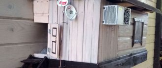
Indoor antenna made from beer cans
Despite the unusual design, it is quite functional, since it is a classic dipole, especially since the dimensions of a standard can are perfectly suitable for the arms of a decimeter range vibrator. If the device is installed in a room, then in this case it is not even necessary to coordinate with the cable, provided that it is not longer than two meters.
Indoor antenna design based on beer cans
Designations:
- A - two cans with a volume of 500 mg (if you take tin and not aluminum, you can solder the cable instead of using self-tapping screws).
- B – places where the cable shielding is attached.
- C – central vein.
- D – place of attachment of the central core
- E – cable coming from the TV.
The arms of this exotic dipole must be mounted on a holder made of any insulating material. As such, you can use improvised things, for example, a plastic clothes hanger, a mop bar or a piece of wooden beam of appropriate size. The distance between the shoulders is from 1 to 8 cm (selected empirically).
Read also: What is the difference between an orbital sander and an eccentric sander?
The main advantages of the design are fast production (10 - 20 minutes) and quite acceptable picture quality, provided there is sufficient signal power.
Types of receiving antennas
A set of channels is provided to users through broadcasting on specific frequency bands. There is analogue television and digital. Each broadcast occurs on different bands, the antenna must be appropriate.
- For terrestrial analogue TV, a meter antenna (MF) is required. The signal is transmitted and received in the range of 1-300 MHz.
- Digital broadcasting is performed on shorter waves, which correspond to the range of 0.3-3 GHz. A decimeter antenna (UHF) is required, which will pick up shorter waves than when transmitting an analog signal.
- If you need to receive meter and decimeter waves at once, then you need broadband devices. The design contains vibrators of different sizes to operate at different frequencies.
Depending on the location, there are external and internal. The first ones are installed outdoors, on the roofs of houses and other places. They can be used in an apartment building for all residents at once or for one in the case of an individual connection. Internal ones are installed at home. They may not even have a cable, but are attached directly to the TV.
There are also:
- active antennas, on which the signal is amplified by a connected amplifier (power is received from an external unit inside the apartment or from a television signal receiver - a TV or set-top box);
- passive - they themselves amplify the receiving signal due to their design (observance of the size of the antenna and the shape of the conductors is required).
What are you connecting the antenna to?
To digital set-top box
52.89%
To TV
47.11%
Voted: 467
Making an antenna from copper wire
There is a design that is much simpler than the previous version, which only requires a piece of copper wire. We are talking about a narrow band loop antenna. This solution has undoubted advantages, since in addition to its main purpose, the device plays the role of a selective filter that reduces interference, which allows you to confidently receive a signal.
Fig.4. A simple UHF loop antenna for receiving digital TV
For this design, you need to calculate the length of the loop; to do this, you need to find out the frequency of the “digit” for your region. For example, in St. Petersburg it is broadcast on 586 and 666 MHz. The calculation formula will be as follows: LR = 300/f, where LR is the length of the loop (the result is presented in meters), and f is the average frequency range, for St. Petersburg this value will be 626 (the sum of 586 and 666 divided by 2). Now we calculate LR, 300/626 = 0.48, which means the length of the loop should be 48 centimeters.
If you take a thick RG-6 cable with braided foil, it can be used instead of copper wire to make a loop.
Now let's tell you how the structure is assembled:
- A piece of copper wire (or RG6 cable) with a length equal to LR is measured and cut.
- A loop of suitable diameter is folded, after which a cable leading to the receiver is soldered to its ends. If RG6 is used instead of copper wire, then the insulation from its ends is first removed, approximately 1-1.5 cm (the central core does not need to be cleaned, it is not involved in the process).
- The loop is installed on the stand.
- The F connector (plug) is screwed onto the cable to the receiver.
Note that despite the simplicity of the design, it is most effective for receiving “digits”, provided that the calculations are carried out correctly.
How to replace a matching printed circuit board with a cable loop
The use of a printed circuit board to match the antenna with a coaxial cable allows you to make the antenna more compact.
If there is no desire or opportunity to make a printed circuit board, then without losing the quality of the antenna’s performance, it can be replaced with a loop, which is also called a U-elbow, which is a section of television cable bent in half, connected to the antenna according to the diagram, as in the photograph below.
To make a matching loop, you need to take a piece of television cable 162 mm long, with which the antenna will be connected to the TV. Cut its ends and solder the central cores to the ends of the ring, the distance between which should be 60 mm. Next, the end of the cable going to the TV is cut and its central core is soldered to either end of the antenna ring, and the shielding wire is connected to the shielding wires of the loop, as shown in the photograph.
When soldering the shielding braid, care must be taken so that the insulation of the central core does not melt and the braid does not come into contact with it.
The photo shows the soldering of a cable to an antenna ring made of aluminum wire with a diameter of 3 mm. Since it is difficult to solder wires to aluminum with soft solder, the ends of the ring were slightly flattened, holes were drilled in them, and brass petals were secured with rivets. The central cores of the cable are soldered securely to the petals.
Do-it-yourself MV and UHF indoor antenna
If, in addition to UHF, there is a desire to receive MF, you can assemble a simple multiwave oven, its drawing with dimensions is presented below.
Indoor multiwave (MV and UHF) antenna
To amplify the signal, this design uses a ready-made SWA 9 unit; if you have problems purchasing it, you can use a home-made device, the diagram of which was shown above (see Fig. 2).
It is important to maintain the angle between the petals; going beyond the specified range significantly affects the quality of the “picture”.
Despite the fact that such a device is much simpler than a log-periodic design with a wave channel, it nevertheless shows good results if the signal is of sufficient power.
Antenna efficiency
The antenna will work without an amplifier.
Signal reception is ensured due to the design of the receiver. The form is designed in such a way that you can set up digital TV channels on your TV.
The design is primitive, so to receive an over-the-air signal you need:
- so that the power of the incoming signal to the antenna is at a high level:
- the repeater must be located near your current location;
- there should be no obstacles on the signal path (tall buildings, hills, etc.);
- so that the signal is present at all. There are areas where the digital terrestrial television signal does not arrive at all. Then, no matter what the antenna is, it will not be possible to tune the channels on the TV receiver.
DIY figure eight antenna for digital TV
Let's consider another common design option for receiving “digits”. It is based on the classic scheme for the UHF range, which, because of its shape, is called “Figure Eight” or “Zigzag”.
Rice. 6. Sketch and implementation of the digital eight
Design dimensions:
- outer sides of the diamond (A) – 140 mm;
- internal sides (B) – 130 mm;
- distance to the reflector (C) – from 110 to 130 mm;
- width (D) – 300 mm;
- the pitch between the rods (E) is from 8 to 25 mm.
The cable connection location is at points 1 and 2. The material requirements are the same as for the “Rhombus” design, which was described at the beginning of the article.
I ask you, what could be more interesting to study than alternating current?
Nikolo Tesla.
All possible matching and balancing schemes when connecting an antenna and a coaxial feeder are described in sufficient detail in any primer on antennas. However, not only an inexperienced anonymous person, but also visitors to fairly serious forums often fall into a state of shock when they see, for example, a matching scheme for a Pistolkors vibrator using a half-wave U-elbow. “This is some kind of nonsense!” - they write - “How can a circuit work in which one end is connected to an antenna and the other is hanging in the air? The circuit is not closed!” This is not nonsense, dear anonymous, this is alternating current flowing along a “long line”. It would be more accurate to say - an electromagnetic wave propagating along a long line. Let's figure this out...
To begin with, let’s decide why we should fence this garden with loops, loops, glasses, etc. If the antenna has an input impedance of 50(75) Ohms, can it be directly connected to the feeder? It is possible, but not always. Due to the skin effect, the RF current flows in a thin surface layer of the conductor several micrometers thick. As a result, a coaxial cable can be represented as a system of three conductors - a central one, the inner surface of the braid and an outer surface of the braid that is completely independent of it. If a coaxial cable is connected directly to a symmetrical vibrator, then the latter will be loaded asymmetrically, its directional pattern will be distorted, and this effect will be further aggravated by connecting the outer side of the braid to the vibrator, which then becomes part of the antenna. As a result, we can come to a situation where an antenna with such a connection becomes equivalent to a piece of wire thrown onto a tree. So, in order to “set the braid to zero”, you will have to trick the loops, dear anonymous. This process is called symmetry .
The Pistolkors symmetrical vibrator has an input resistance of about 300 Ohms and it will have to not only be balanced, but also simultaneously transform this resistance to the feeder resistance. This process is called reconciliation . For a loop vibrator, the point of zero potential is located at its geometric center. Moreover, it appears to consist of two identical halves (“ 0-a ” and “ 0-b ”) with antiphase voltage sources and resistances of 150 Ohms. We connect “ 0-a ” to “ 0-b ” using a half-wave loop. The loop does not change the resistance, but reverses the phase by 180°.
As a result, at the input of the coaxial cable there are two in-phase parallel sources with resistances of 150 Ohms. The voltages are summed, the resistance due to the parallel connection is divided in half and the 75-ohm feeder is matched to the source. In complex antennas, for example Uda-Yagi, by varying the size, primarily the distance to the reflector, you can make the input impedance of the vibrator equal to 200 Ohms. Then the “halves” of the vibrator will be 100 Ohms each and it is matched in the same way with the 50 Ohm feeder. Since the properties of a half-wave loop do not depend on its characteristic impedance, the question arises of what resistance to choose. Usually the same cable is used as for the feeder or pigtail. The bandwidth of such a system is about 30% of the center frequency, which is sufficient in most cases. However, if you use a loop with a characteristic impedance equal to the resistance of the vibrator halves (150 or 100 Ohms), then it will operate in the traveling wave mode and will not limit the bandwidth of the antenna-feeder system as a whole. So if you come across a piece of coax with a characteristic impedance of 150 (100) Ohms, save it for the U-elbow.
It is not for nothing that at the beginning of the article we cited a quote from N. Tesla, who stood at the origins of the modern power supply system. As is known, with a symmetrical load in a three-phase network, you can refuse to use the neutral, since the sum of the currents from all phases in it is zero. In our case, there is an antiphase voltage at the ends of the loop and in the 0-0` the sum of the currents is zero, so this piece of wire can be thrown away and the circuit will remain operational. Many experts advise leaving this connection. Indeed, in this case the antenna works better on meter and decimeter waves. However, sometimes, like with the Butterfly or Amos antenna, the zero point is “in the air” and there is simply nowhere to connect. In a microwave, an extra piece of wire is already a long line, so it is better to use minimally short leads without unnecessary connections. In the following figure, on the left you can see how to connect the loop and feeder at 3G , and on the right - how not to.
In the case of a split vibrator having a resistance of about 75 (50) Ohms, like the Uda-Yagi antenna of the DL6WU design, you can also use a half-wave loop with a small addition for balancing. The vibrator also appears to consist of two antiphase halves with resistances of 37.5 (25) Ohms. A quarter-wave transformer is connected to each half, which transforms it into a value of 150 (100) Ohms at points a and b (see the formula for a quarter-wave transformer in the article on long lines), after which the same circuit with a half-wave loop works. Of course, there is no need to make a break at point a , this was done only for a better understanding of the working mechanism. A really practical loop design for a 75(50) ohm vibrator consists of two pieces with an electrical length of 3λ/4 and λ/4 of the same wave impedance.
Since the characteristic impedance of the feeder practically coincides with the input impedance of the split vibrator, it would be good to connect it directly, while cutting off the flow of current along the outer side of the braid. Such balancing exist and are called current-cut circuits. One of them is a circuit with a quarter-wave glass . The idea is that the current on the outer side of the braid enters an additional short-circuited quarter-wave section of line with infinite resistance (unfortunately, only infinite in theory), is cut off by it, and does not flow beyond this glass. The difficulty lies in some hemorrhoids in the design of such a glass, since it hangs on the feeder. How to simplify this task well.
Another way to cut off stray current on the outside of the feeder braid, with less design complexity, is to use a quarter-wave loop . In principle, this is the same quarter-wave short-circuited segment, only made not in the form of a glass, but in the form of a two-wire long line. Otherwise, we can say that parallel to the main feeder, or rather its outer side of the braid, the same wire with an antiphase current from the other half of the vibrator is connected, and these antiphase currents are then mutually compensated at the point of closure. This scheme was once widely popularized for the Triple Square antenna. The cable can be made from the same tubes as the vibrator, or from a coaxial cable, the same as the feeder. Another method of balancing is called coaxial-slot . Two λ/4 cuts are made in the outer tube of the coaxial line. The upper halves of the tube are connected to the vibrator, and the central conductor is shorted to one of the halves. This diagram can be simplified by making the semicircular halves flat.
Loops and cups are resonant circuits and limit the bandwidth, but they are quite broadband, with a bandwidth of up to 60% of the center frequency. At the same time, for antennas such as the Kharchenko antenna for digital television, this is not enough. The way out is to use broadband transformers on long lines with ferrite cores, SHPTL - in our literature, TLT - in foreign literature. Theoretically, such SPTLs in traveling wave mode have no frequency limitations, but in practice their bandwidth is . Such transformers are used in all Polish amplifiers and balancers with a transformation ratio of 4:1. They are wound on a ferrite ring or on a “binocular” and work well in both 300:75 and 200:50 modes, having a bandwidth covering almost the entire UHF range.
To match (balance) antennas with an input impedance of 75 (50) Ohms, you can also use SHPTL, but with a transformation ratio of 1:1. For this purpose, you can remake the “Polish” transformer by removing one of the lines from it and making connections according to the diagram in the last figure under the letter d). Sometimes you can find the same SPTLs, but implemented in the form of strip lines on a printed circuit board. At frequencies above 1 GHz, you can simply put several ferrite rings on the feeder, obtaining a surrogate SHTL. Although, due to the strong frequency dependence of the magnetic permeability of ferrite and the limitations of its performance at microwave frequencies, this solution looks rather doubtful, for reliable current cutoff, it is possible to combine this solution with a quarter-wave cup, as is done in the design of a collinear antenna.
In foreign literature, matching and balancing schemes are called in one word balun . This concept has recently become widespread in our country. Baluns are divided into two classes: Voltage balun and Current balun . To fully understand their differences, the load should always be considered not as a two-terminal network, but as a three-terminal network with a “neutral”. Even if the “neutral” is not explicitly specified, as in the example with the Pistolkors vibrator, it must be represented virtually. However, this is the topic of a separate large article, which can be read in English. If, as is customary on our website, we approach the issue in a simplified manner, then the difference between Voltage and Current baluns is easily visible from the following diagram:
We see that the current balun is essentially a choke for common-mode current, while the Voltage balun performs voltage transformation. The above-mentioned ferrite SPTLs according to schemes a) - e) are classic current baluns or, according to the author’s name, Guanella current . The glass and the loop can also be classified as Current balun, but the half-wave loop belongs to the Voltage balun class. The class of voltage baluns also includes Ruthroff voltage :
The higher the frequency, the higher the harmful effects of parasitic inductances and lead capacitances. In addition, popular ferrite materials (for example, 67th) stop working in the microwave. Therefore, the use of ferrite SPTLs at frequencies above 1000 MHz seems inappropriate. But the transmission line works great without ferrite. For example, the coaxial slot balun is actually a 1:1 modification of the Rutrof voltage balun. To make sure of this, look carefully at the connection diagrams.
In general, designing effective microwave baluns is quite a difficult task. For this reason, many refuse to use special balancing devices, some quite consciously (why should I bother with this theory of yours, it works fine anyway!), and some out of ignorance, as, for example, did prof. Marshall. However, the best way to solve the problem of matching and balancing is to use antennas that do not require either one. Such antennas are designed specifically for the microwave range, for example a patch antenna.
Useful links:
- - DL2KQ;
- — Analysis of various types of baluns in the LTspice simulator from DL2KQ;
- - RA6FOO;
- - RA6FOO;
- Description of little-known ones from microwaves101.com (in English);
- VK()
- Facebook()
- Comments (75)
Comments
«345678
#71 Stepan 10/08/2019 11:27 I made my own .lay file using the sketch from your LiveJournal article. Is the difference significant (in quality)? Does it make sense to redo it? I just already made scarves from my file :(
Quote
#72 yurik82 10/08/2019 11:34 This was a sketch as close as possible to the sample that is sold on the market (one of many). It shows obvious shortcomings aimed at simplifying and reducing the cost of production by sacrificing a little coordination
Quote
#73 Stepan 10/08/2019 21:52 But here’s a question: can the jumper on the board be made with a single-core wire, or is it better to use a strip of foil with insulation made of fluoroplastic film?
Quote
#74 yurik82 10/09/2019 07:20 Better with a wire
Quote
#75 Ruslan 02/23/2020 00:37 Hello. A question. I need a 50 Ohm 1k1 isolation transformer. Antenna for two bands vhf and vhf. Is it possible to make swa 300:75 from a board?
Quote
«345678
Update list of comments
Add a comment
Comments from anonymous people (not registered site users) are pre-moderated. Moderation does not take place in real time and there may be a delay. We ask particularly impatient anonymous people not to publish the same post in a row. In this case, the post may be rejected by the moderator. Messages from disposable and non-existent emails are also deleted. The site has a forum and comments on social networks, where there are many more opportunities for communication.
©3G-Aerial
Homemade antenna for DBT T2
Actually, all of the examples listed above are capable of receiving DBT T2, but for variety we will present a sketch of another design, popularly called “Butterfly”.
Decimeter antenna "Butterfly"
The material can be used as plates made of copper, brass, aluminum or duralumin. If the structure is planned to be installed outdoors, then the last two options are not suitable.
Do-it-yourself decimeter antenna for TV: diagrams and drawings with dimensions
Despite the rapid development of satellite and cable television, the reception of terrestrial television broadcasts still remains relevant, for example, for places of seasonal residence.
It is not at all necessary to buy a finished product for this purpose; a home UHF antenna can be assembled with your own hands.
Before moving on to considering the designs, we will briefly explain why this particular range of the television signal was chosen.
Why DMV?
There are two good reasons to choose designs of this type:
- The thing is that most channels are broadcast in this range, since the design of repeaters is simplified, and this makes it possible to install a larger number of unattended low-power transmitters and thereby expand the coverage area.
- This range is selected for digital broadcasting.
Indoor TV antenna “Rhombus”
This simple, but at the same time, reliable design was one of the most common in the heyday of on-air television broadcasting.
Rice. 1. The simplest homemade Z-antenna, known under the names: “Rhombus”, “Square” and “People’s Zigzag”
As can be seen from the sketch (B Fig. 1), the device is a simplified version of the classic zigzag (Z-design). To increase sensitivity, it is recommended to equip it with capacitive inserts (“1” and “2”), as well as a reflector (“A” in Fig. 1). If the signal level is quite acceptable, this is not necessary.
The material you can use is aluminum, copper, and brass tubes or strips 10-15 mm wide. If you plan to install the structure outdoors, it is better to abandon aluminum, since it is susceptible to corrosion. Capacitive inserts are made of foil, tin or metal mesh. After installation, they are soldered along the circuit.
The cable is laid as shown in the figure, namely: it did not have sharp bends and did not leave the side insert.
UHF antenna with amplifier
In places where a powerful relay tower is not located in relative proximity, you can raise the signal level to an acceptable value using an amplifier. Below is a schematic diagram of a device that can be used with almost any antenna.
Rice. 2. Antenna amplifier circuit for the UHF range
List of elements:
- Resistors: R1 – 150 kOhm; R2 – 1 kOhm; R3 – 680 Ohm; R4 – 75 kOhm.
- Capacitors: C1 – 3.3 pF; C2 – 15 pF; C3 – 6800 pF; C4, C5, C6 – 100 pF.
- Transistors: VT1, VT2 – GT311D (can be replaced with: KT3101, KT3115 and KT3132).
Inductance: L1 - is a frameless coil with a diameter of 4 mm, wound with copper wire Ø 0.8 mm (2.5 turns must be made); L2 and L3 are high-frequency chokes 25 µH and 100 µH, respectively.
If the circuit is assembled correctly, we will get an amplifier with the following characteristics:
- bandwidth from 470 to 790 MHz;
- gain and noise factors – 30 and 3 dB, respectively;
- the value of the output and input resistance of the device corresponds to the RG6 cable – 75 Ohm;
- the device consumes about 12-14 mA.
Let's pay attention to the method of power supply; it is carried out directly through the cable.
This amplifier can work with the simplest designs made from improvised means.
Indoor antenna made from beer cans
Despite the unusual design, it is quite functional, since it is a classic dipole, especially since the dimensions of a standard can are perfectly suitable for the arms of a decimeter range vibrator. If the device is installed in a room, then in this case it is not even necessary to coordinate with the cable, provided that it is not longer than two meters.
Indoor antenna design based on beer cans
Designations:
- A - two cans with a volume of 500 mg (if you take tin and not aluminum, you can solder the cable instead of using self-tapping screws).
- B – places where the cable shielding is attached.
- C – central vein.
- D – place of attachment of the central core
- E – cable coming from the TV.
The arms of this exotic dipole must be mounted on a holder made of any insulating material. As such, you can use improvised things, for example, a plastic clothes hanger, a mop bar or a piece of wooden beam of appropriate size. The distance between the shoulders is from 1 to 8 cm (selected empirically).
The main advantages of the design are fast production (10 - 20 minutes) and quite acceptable picture quality, provided there is sufficient signal power.
Making an antenna from copper wire
There is a design that is much simpler than the previous version, which only requires a piece of copper wire. We are talking about a narrow band loop antenna. This solution has undoubted advantages, since in addition to its main purpose, the device plays the role of a selective filter that reduces interference, which allows you to confidently receive a signal.
Fig.4. A simple UHF loop antenna for receiving digital TV
For this design, you need to calculate the length of the loop; to do this, you need to find out the frequency of the “digit” for your region. For example, in St. Petersburg it is broadcast on 586 and 666 MHz.
The calculation formula will be as follows: LR = 300/f, where LR is the length of the loop (the result is presented in meters), and f is the average frequency range, for St. Petersburg this value will be 626 (the sum of 586 and 666 divided by 2).
Now we calculate LR, 300/626 = 0.48, which means the length of the loop should be 48 centimeters.
If you take a thick RG-6 cable with braided foil, it can be used instead of copper wire to make a loop.
Now let's tell you how the structure is assembled:
- A piece of copper wire (or RG6 cable) with a length equal to LR is measured and cut.
- A loop of suitable diameter is folded, after which a cable leading to the receiver is soldered to its ends. If RG6 is used instead of copper wire, then the insulation from its ends is first removed, approximately 1-1.5 cm (the central core does not need to be cleaned, it is not involved in the process).
- The loop is installed on the stand.
- The F connector (plug) is screwed onto the cable to the receiver.
Note that despite the simplicity of the design, it is most effective for receiving “digits”, provided that the calculations are carried out correctly.
Do-it-yourself MV and UHF indoor antenna
If, in addition to UHF, there is a desire to receive MF, you can assemble a simple multiwave oven, its drawing with dimensions is presented below.
Indoor multiwave (MV and UHF) antenna
To amplify the signal, this design uses a ready-made SWA 9 unit; if you have problems purchasing it, you can use a home-made device, the diagram of which was shown above (see Fig. 2).
It is important to maintain the angle between the petals; going beyond the specified range significantly affects the quality of the “picture”.
Despite the fact that such a device is much simpler than a log-periodic design with a wave channel, it nevertheless shows good results if the signal is of sufficient power.
DIY figure eight antenna for digital TV
Let's consider another common design option for receiving “digits”. It is based on the classic scheme for the UHF range, which, because of its shape, is called “Figure Eight” or “Zigzag”.
Rice. 6. Sketch and implementation of the digital eight
Design dimensions:
- outer sides of the diamond (A) – 140 mm;
- internal sides (B) – 130 mm;
- distance to the reflector (C) – from 110 to 130 mm;
- width (D) – 300 mm;
- the pitch between the rods (E) is from 8 to 25 mm.
The cable connection location is at points 1 and 2. The material requirements are the same as for the “Rhombus” design, which was described at the beginning of the article.
Homemade antenna for DBT T2
Actually, all of the examples listed above are capable of receiving DBT T2, but for variety we will present a sketch of another design, popularly called “Butterfly”.
Decimeter antenna "Butterfly"
The material can be used as plates made of copper, brass, aluminum or duralumin. If the structure is planned to be installed outdoors, then the last two options are not suitable.
Bottom line: which option to choose?
Oddly enough, the simplest option is the most effective, so the “loop” is best suited for receiving a “digit” (Fig. 4). But, if you need to receive other channels in the UHF range, then it is better to stop at “Zigzag” (Fig. 6).
- Recommendations.
- The antenna for the TV should be directed towards the nearest active repeater, in order to select the desired position, you should rotate the structure until the signal strength is satisfactory.
- If, despite the presence of an amplifier and reflector, the quality of the “picture” leaves much to be desired, you can try installing the structure on a mast.
Do-it-yourself decimeter antenna mounted on a mast
In this case, it is necessary to install lightning protection, but this is a topic for another article.
Source: https://www.asutpp.ru/decimetrovaya-antenna-svoimi-rukami.html
Bottom line: which option to choose?
Oddly enough, the simplest option is the most effective, so the “loop” is best suited for receiving a “digit” (Fig. 4). But, if you need to receive other channels in the UHF range, then it is better to stop at “Zigzag” (Fig. 6).
Recommendations.
The antenna for the TV should be directed towards the nearest active repeater, in order to select the desired position, you should rotate the structure until the signal strength is satisfactory.
If, despite the presence of an amplifier and reflector, the quality of the “picture” leaves much to be desired, you can try installing the structure on a mast.
Do-it-yourself decimeter antenna mounted on a mast
In this case, it is necessary to install lightning protection, but this is a topic for another article.
How to make an antenna
In addition to the description of the manufacturing process, the advantages and disadvantages of each antenna for digital TV will be described. Not every type of antenna can be quickly made for a TV. This is explained by the complexity of the design and the need for appropriate calculations.
Antenna cable loop
This can always be done if the old antenna has stopped showing.