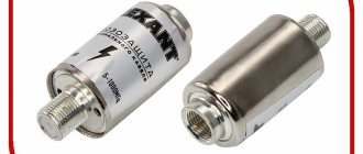
Eurosky SWA-3
broadband antenna amplifier
watch here https://coppersat.tv
The Eurosky SWA-3 broadband antenna amplifier is installed in external antennas, grilles, meshes, or as they also say (Polish antennas), to amplify the TV signal. Depending on the distance to the television center, various models are used that have different amplification coefficients and allow receiving television programs at a distance from 0 to 150 km from the television center. SWA broadband antenna amplifiers have an input impedance determined by the antenna design of 300 Ohms, an output impedance of 75 Ohms, use a supply voltage of 9 V to 15 V and are designed to amplify the frequency range 49 MHz - 790 MHz. The voltage supply to the broadband amplifiers is carried out by adapters that differ only in the design of the housing and the output voltage is 12V. Wideband antenna amplifiers SWA are designed to increase the signal level and compensate for losses in transmission lines. Such amplifiers are produced using SMD technology using the most modern low-noise transistors, which are manufactured by leading foreign companies - ITT, Siemens, Philips, etc. They can be used in various designs of broadband antennas. Thanks to fully automated multiple monitoring, the broadband amplifiers have good reliability, and thanks to the protective coating, they are resistant to atmospheric agents.
Currently, the largest range consists of broadband antenna amplifiers SWA, WS, RA, RAE, GPS, etc. They have different circuit designs, which allows, through simple selection, to achieve the required results in areas with different levels of received signal. In areas with a relatively good level of received signal, amplifiers with one amplification stage (single-stage) SWA-1, SWA-1 /LUX, PA-2, S&A-110 are usually used. In areas with insufficient received signal level, use two-stage (two-stage) amplifiers WS-2, SWA-3, SWA-4/LUX, SWA-5 (SWA-6), SWA-7, SWA-8, SWA-9, PA- 5, S&A-130, PA-9, S&A-140, PA-10, S&A-120, PAE-14, PAE-42, PAE-43, PAE-44, PAE-45, PAE-65, PAE-65TS, WA-031, WA-032, WA-041, WA-042, WA501S-1.
The table shows the technical parameters and characteristics of SWA and their analogues pa, gps, pae. The noise figure and gain are given in dB, the recommended distance to the telecentre is given in km.
Price of broadband antenna amplifier SWA-3 Eurosky
watch here https://coppersat.tv
Reasons for a weak signal
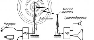
The digital signal transmitted by the repeater may be too weak to be received for the following reasons:
- Large distance to the transmission tower. The same “inverse square law” applies to radio waves in the UHF range on which digital television broadcasts, as for any other type of electromagnetic radiation.
- Absorption of waves by the atmosphere. The air itself is practically radio transparent, but dust, fog, and moisture can scatter and reflect the signal.
- Obstacles in the path of radio waves. UHF broadcasting is received in the line of sight zone, the waves practically do not bend around obstacles. Therefore, if there is some object opaque to radio waves between the repeater and the receiving antenna (buildings, hills, a forest of tall trees), at best the signal will be weakened. This is more appropriate in cases where indoor antennas are used: any walls, even thin ones, absorb electromagnetic waves.
- Only reflected signals are received. If there is an object that screens radio waves on the direct line between the antenna and the repeater, you will only have to receive the television signal that will be reflected from other objects (for example, neighboring buildings). Such radiation is many times weaker than that initially broadcast from a television tower.
- Poor quality receiving equipment: antenna with low sensitivity, cable with high resistance, etc.
In a word, there can be a lot of reasons. In most cases, influencing them is difficult or even impossible. Therefore, in order to watch TV without freezing and scattering of the picture, you need to choose the right way to improve reception.
Antenna with built-in amplifier
Antenna preamplifier is an active element of the antenna installation, designed for primary signal amplification. The amplifier board for the antenna is installed directly on the antenna itself, turning it into an active type receiver. An active TV wave catcher is needed in cases where the electromagnetic field strength in the reception area is insufficient or the coaxial cable is too long, which leads to additional signal losses.
In ready-made factory-produced antennas, the built-in amplification device is included directly in the antenna structure and is hidden from view by a plastic housing. The supply voltage is supplied to the electronic board via a separate wire or directly through a TV cable. In some modifications, power comes from a digital tuner.
A modern TV antenna with an amplifier, as well as a separate preamplifier that you purchase, are distinguished by a number of positive, improved parameters:
- frequency correction technology – cutting off frequency peaks and compensating for dips;
- noise immunity;
- low level of own noise;
- high resistance to intermodulation;
- wide range of permissible supply voltages;
- low power consumption.
The "correct" preamplifier is determined by the strength of the incoming television signals and what is installed between the television antenna and the television (long coaxial cables, signal dividers).
Signal amplification methods
TV antenna signal amplification is achieved in 5 ways:
- Use a higher quality TV antenna than the one you have. Depending on the design, a few decibels of gain can be gained here. Check if your antenna is selected correctly.
- Precise orientation. Almost all devices operating in the UHF range have a clearly oriented diagram and most efficiently receive a signal from one direction. Even a rotation of 5–10 degrees can give a serious increase in signal strength.
- Replace cable. If the distance between the antenna and the television receiver is too large, the lion's share of the received signal power is lost due to the resistance of the conductor. This can be avoided by using a feeder with reduced resistance (for example, with a central core made of pure copper rather than copper-plated steel).
- Move the TV closer to the antenna. The cable becomes shorter: in some cases, even 2–3 meters can be decisive. Reducing the feeder length allows you to avoid unnecessary signal power losses.
- Use an antenna amplifier.
We will dwell on the last option in detail, since it often turns out to be decisive.
Connecting the power supply to the adapter
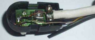
Since I decided to connect the power supply to the crab through one of its F-connectors, to implement this idea I had to make an adapter from an ordinary double wire coming from the power supply to a coaxial cable.
To do this, you need to take a piece of antenna cable 5 cm long, cut one end of it and put on an F-wrap. To the second end, as shown in the photographs, solder the wires coming from the power supply with a shift. The positive terminal is soldered to the central core of the antenna cable.
If you don’t want to mess around, you can install a standard connector in the crab body for connecting power supplies and through it supply voltage to the antenna amplifier through a home-made adapter.
Advantages and disadvantages of connecting an amplifier
Connecting an amplifier to a TV antenna promises tangible benefits:
- a sharp increase in signal power even when using an antenna of the same design;
- no more worrying about where to place your TV. This is especially noticeable if an active antenna is used, in which the amplifier board is part of the structure. In this case, the power of the signal transmitted to the TV is so great that even a whole bay of cable will not become a noticeable obstacle. When using an external amplifier, it will need to be placed closer to the antenna, but the gain in signal power and quality will still be noticeable.
If you intend to connect an amplifier at home, then you need to keep in mind possible disadvantages and limitations:
- The complexity and cost of equipment is increasing. Even if you use the simplest amplification unit that can be soldered, you will need new elements: fasteners, connectors, power supply, special tools, etc. But if you like to work with your hands, this item will not be a problem.
- You will need to take care of nutrition. Any amplifier, in fact, turns the incoming signal into its exact copy, which has greater power. Additional energy must come from somewhere - you need an external adapter that connects to the mains. A set-top box or TV that has the function of an active antenna socket with voltage transmission through the feeder is suitable as a power source.
- The use of amplification is not appropriate in all cases. To create a powerful copy, you need a high-quality original, and if the TV signal is clogged with noise and interference, then the amplifier will boost them too. As a result, even filters and tuners will not always be able to separate the useful signal from the spurious ones.
- Over-amplification will have the opposite effect. If too strong a signal is received at the antenna input, the equipment will consider it non-existent and refuse to play. Therefore, in the area where reliable reception is possible with a passive antenna, you should either refrain from using an amplifier or lower the power factor (if the model has a regulator).
Thus, in order for a TV antenna amplifier to be useful, it requires both a high-quality and a weak signal.
Power supply - adapter for antenna amplifier
If you open any power supply with an adapter, you will see a power transformer, four diodes, an electrolytic capacitor, a simple capacitor, a choke and a voltage stabilizer microcircuit.
All parts of the decoupling circuit, except the power transformer, are installed on the printed circuit board.
Electrical circuit diagram of the power supply for the antenna amplifier with adapter
The power supply shown above in the photo - an adapter for powering the antenna amplifier - is assembled according to a classic electrical circuit diagram. AC mains voltage 220 V is supplied to power transformer T1, which lowers it to 12-15 V. The diode bridge VD1-VD4 rectifies the voltage, the electrolytic capacitor C1 smoothes out the ripples, after which a constant voltage of about 16 V is supplied to the integrated voltage stabilizer DA1.
To eliminate video signal losses and loss of DC voltage, an LC filter is provided at the input of the television receiver, made on elements L1 and C3. Choke L1 does not pass a high-frequency television signal to the power supply circuit, but without losses it allows direct current to flow to the central core of the television cable coming from the television antenna amplifier. Capacitor C3 prevents DC current from flowing from the power supply to the TV input, but passes the TV signal without loss.
When making your own power supply with an adapter, parts can be used of any type. Typically, the current consumption of antenna amplifiers does not exceed 150 mA, which is less than 2 watts, so the transformer for the power supply is suitable for any power with an output voltage of 15-18 V. The choke can be made by winding it on a dielectric base, for example, a strip of fiberglass 5 mm wide, 25-18 V. 30 turns of enameled copper wire with a diameter of 0.1-0.5 mm.
Disadvantages of the presented design of the power supply with adapter
The disadvantages of a power supply adapter of this design include the presence of an unshielded section of the central core of the television cable at the place where it is sealed into the printed circuit board, which, in the presence of interference, for example from a working vacuum cleaner, can lead to interference with the video signal. The penetration of interference can be eliminated by installing an additional shield on the printed circuit board at the place where the wires are soldered.
How to choose the right one
When choosing an amplifier, the TV owner needs to consider the following parameters:
- Required gain range. The device can separately amplify UHF and HF (this is useful if there are local stations transmitting analogue television signals in this range), can be broadband, that is, working with several ranges (however, losses in reception quality are inevitable: universal amplifiers are always worse than highly specialized ones) , or can be multi-band with several amplification blocks for each frequency range.
- Device type. The amplifier can be built-in (that is, a structural part of the active antenna) or external, connected to the cable.
- Type of food. Voltage can be supplied to the amplifier either via a coaxial feeder cable or directly from an external power supply. “Cable” devices are more compact, but amplifiers with separate power supply are more powerful.
How to make your own adapter for supplying power to an antenna amplifier
When making an adapter for supplying power to an isolated antenna amplifier, I decided not to install an additional connector for connecting the power supply, but to use one of the connectors for connecting the F-plug. To do this, we had to remove one of the transformers, limiting the crab's ability to connect only two TVs.
As a result of the modification, only two TVs can be connected to the crab, and its circuitry has changed.
All that remains is to install the LC filter in the crab and the adapter will be ready for use. Since the crab body is made of duralumin, the capacitor lead had to be connected to it through an additionally installed brass terminal, screwed to the adapter body using a screw and nut with a shaped washer.
As a result of the modification, the electrical circuit diagram of the crab acquired the following form. As can be seen from the diagram, transformer T1 remained original, but a choke and two capacitors were added.
To better match the circuit, you can solder a 150 Ohm resistor between the output pins XW2 and XW3. You can install the adapter in any convenient place, directly next to one of the TVs, or, for example, at the cable entrance to the apartment. If you need to connect only one TV, then transformer T1 can be removed, and the right terminal of capacitor C1 can be soldered directly to the central terminal of one of the connectors XW2 or XW3, to which the cable going to the TV can be connected.
Check the result using a multimeter
Once the circuit has been designed and connected, it makes sense to test it and check the characteristics of the resulting design. To do this, you need to have a tester - a multimeter or any other similar device.
Check the following settings:
- The characteristic impedance of the cable should not exceed 75 Ohms.
- The difference between the braid of the coaxial cable and the central core should be several tens of ohms. If the device shows “0”, it means there is a break or short circuit.
- When connecting the central core and braid, the device should show infinity, that is, the maximum of the scale. But if both the braid and the core are disconnected from the antenna and shorted to each other, the result should be zero.
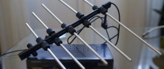
Is the Polish grid suitable for receiving digital television?
The Polish mesh antenna at one time quickly spread throughout the country and gained popularity among many users. This equipment is easy to maintain and does not require additional modifications after installation. With the advent of DVB-T2 digital broadcasting in the country, users began to find various amplifiers for this type of antenna, allowing them to capture a digital signal and broadcast it to a TV.
The antenna array itself is broadband. In other words, such equipment is capable of receiving various signals of both meter and decimeter range lengths. This unique property allows the device to catch signals from digital TV channels in DVB-T2 format.
The Polish grid is not the most suitable option used for long-distance reception of digital TV channels. This is primarily due to the fact that the device requires modifications and modernization before it begins to function in the required range.
Wiring of the built-in amplifier SWA
A passive antenna can be amplified by installing an SWA card on it. The most delicate place in this process is the wiring of contacts. The video shows the entire process from choosing an amplifier to its correct installation. Just follow the recommendations and success is inevitable.
If your antenna with an amplifier does not stably receive a DVB-T2 digital television signal, then often the problem is not that the amplifier is weak, but that it is not needed there at all. Yes, yes, after the advent of digital terrestrial television, the situation with signal reception has changed a lot in some respects and in many cases, the amplifier in the antenna simply becomes unnecessary, moreover, it becomes the cause of an unstable and sometimes completely absent signal.
I have already written about the cause of this phenomenon and methods of combating it here, so I will not repeat myself and will not explain why the alteration is needed, which I want to talk about in this note. Namely, how to convert the amplifier for the “Polish” antenna into a matching board.
What will you need for this? Actually the amplifier itself, maybe even a faulty one, a 3 centimeter piece of wire and a soldering iron. Task: Make a matching board from the amplifier board, which is not always available in stores.
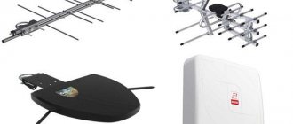
Antenna amplifier installation
Having an active antenna whose gain does not suit you, or with an active element that has become unusable, you have the opportunity to purchase a new amplifier for it from a large assortment on the TV market and install it yourself.
The amplifying electronic board is mounted directly on the designated place provided for in the antenna design. After this, it needs to be secured with nuts on the studs. To protect the microcircuit elements from external moisture and sun, it is placed in a protective plastic casing with a rubber seal.
Buyers often face the question - how to check the antenna amplifier board before making a purchase? There is such a way. It's not perfect, but 9 times out of 10 it detects a faulty device.
If you have electrical knowledge, here is our recommendation:
- supply power to the amplifier - 12 volts;
- Place the multimeter probes on the second amplification stage;
- record the voltage value;
- If the board is working, then when it comes into contact with a screwdriver, the voltage at the emitter increases.
How does the Polyachka TV antenna work when receiving a digital signal?
The basic kit does not imply the use of equipment to receive 10 or 20 digital TV channels distributed throughout the country . In any case, until there is an official update to the antenna from the manufacturer, you will have to improve it yourself in order to achieve the required signal level. With proper modification, the Polish array responds well to long-range digital signal reception.
There is a small percentage of probability that, due to the similar signal reception range, the antenna can partially capture the image and broadcast sound even without modification. However, the signal will be weak and difficult to detect on a permanent basis. The standard amplifier that comes with antenna arrays is also not suitable for working with digital television. It needs to be upgraded to improve signal reception quality.
A positive effect is achieved only if the antenna is located close to the repeater tower. In this case, a minimum amount of signal amplification or reduction is required to achieve a high-quality image using standard devices available in stores and electronics markets.
What does SWA mean in text?
In sum, SWA is an acronym or abbreviation word that is defined in simple language. This page illustrates how SWA is used in messaging and chat forums, in addition to social networks such as VK, Instagram, Whatsapp and Snapchat. From the table above, you can view all the meanings of SWA: some are educational terms, others are medical terms, and even computer terms. If you know of another definition of SWA, please contact us. We will enable it during the next update of our database. Please be aware that some of our acronyms and their definitions are created by our visitors. Therefore, your suggestion for new abbreviations is welcome! As a return, we have translated the acronym SWA into Spanish, French, Chinese, Portuguese, Russian, etc. You can further scroll down and click the language menu to find meanings of SWA in other 42 languages.
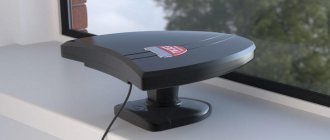
Main technical characteristics of the Polish antenna
The “Polyachka” range operates from 40 to 800 MHz. This allows you to receive signals and watch TV shows from channels 1 to 20.
With a little modification and connection of the amplifier, it also becomes possible to watch TV channels from 21 to 69. Additionally, the basic configuration of any array antenna model includes its own signal amplification of up to 13 decibels, as well as a characteristic impedance of 300 ohms.
The dimensions of the equipment are relatively small (80x60 cm), weight is 1.5 kg.
The list of antenna components upon purchase is impressive:
- active vibrators (UHF, MV);
- passive vibrators (directors);
- slats for attaching base lines of waveguides and plastic housings;
- mounting an antenna with a reflector;
- reduced voltage units;
- various amplifier models at the buyer’s choice;
- standard plugs for connection.
Coaxial cables required to connect the device to the translator are purchased separately.