Antenna with an amplifier of the “Grid” type and digital television – are they compatible?
The grille does not accept DVB T2, what should I do? Why is the antenna not working? How to use the “pole” without an amplifier? All this and other questions are in this article.
Hello, dear visitors! The author of the site Blogvp.ru welcomes you!
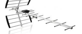
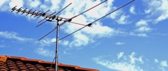
It is no secret that the “Polish Grid” antenna has gained wide popularity among users. It has been serving the people for a long time and often torments its users. Now, analog television is being replaced by digital television, DVB-T2, and many people have various questions about the use of this antenna.
I have previously written about the use of a Polish antenna for DVB-T2, answering in the comments and not much in the articles themselves. Therefore, in this note, in one place, I will try to collect more complete information about the use of this type of antennas, both for analogue and digital television.
How to check a TV antenna
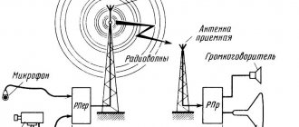
A television antenna is a device designed for transmitting equipment. And, depending on what device is used and a certain number and quality of channels are received.
Now, in most cases, satellite dishes are used. They are equipped with a certain set of equipment: dish, cable, converter, receiver, and so on.
How to check the performance and technical potential of a television antenna? But, like any other equipment, this device can fail not only due to mechanical damage, but also if connected incorrectly. In such situations, you need to know how to check a television antenna without resorting to the services of specialists. There are a number of reasons why on TV:
- The antenna is not tuned (there is a signal strength scale, but no quality scale).
- Absence of a power circuit in the receiver-converter flow (both scales are zero, which means there is no contact).
- The converter is faulty (the signal strength may be present, but there is no quality scale).
- The memory in the receiver settings has disappeared (during a long “rest”).
First of all, you should pay attention to the TV cable.
It should be intact and without any crimps.
- If this is a private home, then you can check the resistance of both ends of the TV cable. First you need to unplug all equipment from the outlet. Then disconnect the wire from the antenna and from the TV. And in the same way, use a tester to check the braiding and the central core for short circuits. Here, the serviceability of the cable is indicated by an infinite resistance value. But, if you short-circuit the central core and braid, the multimeter should show a value close to “0”.
- If this is a multi-story building, then you will only have to check the functionality of one end of the cable (with a plug). For this, a multimeter (tester) is used to measure the resistance between the braid and the central core of the wire. A value of several tens of ohms is considered a normal value. If it is greater than or close to “0”, a break or short circuit has occurred. In this case, it is better to find out whether the neighbors have a signal and, if so, then the problem is in the junction box or in the area from it to the plug.
When the device detects a malfunction, it is necessary, first, to find the weak point of the cable. This usually occurs in places where there are sharp bends, connected sections, or where the wind sways.
If everything is fine with the TV cable, the cause of the problem should be looked for elsewhere. The most common problem is a broken antenna head (LNB) or DISEQC (switch). This is usually understandable if some TV channels suddenly stop showing.
The converter can fail due to precipitation, short circuits and sudden voltage surges. To check whether this problem is really due to a malfunction of the converter or disk, you must:
- Disconnect
- Unscrew the LNB head from the cable.
- Turn on a channel that has stopped working.
Tip 1: How to check your TV cable
In the first case, you do not have access to both ends of the cable, so you will only have to take measurements from the antenna plug side. 2 Measure the resistance between the central core and the cable braid with a tester (multimeter), normally it should be several tens of ohms. If it is infinitely large, this indicates a cliff.
Conversely, if it is close to zero, a short circuit has occurred. Ask your neighbors if they have a TV signal.
If there is, then the fault should be looked for in the area from the junction box in the entrance to the antenna plug. 3 If you live in a private home and have access to both ends of the cable, first disconnect the cable from the TV (pull out the plug) and from the antenna - in the latter case, you may need to unscrew a few screws. Now check the central core and braid for short circuit; a working cable should have infinite resistance.
advocatus54.ru
VIRGO wrote: If within sight of the “TV tower”, then practice has shown that it is easier to set the “zero” (SWA-0), this is a permanent balancing trans. without amplifier. Exactly, with a sufficient signal level this is much better.
Not only do hemorrhoids disappear with the failure of the amplifier, but nothing trivially distorts the signal. This is especially noticeable with digital TV - screw amplifiers. Remind me in a personal message if anything happens. PS Instead of “Thank you”, it is customary to press the plus sign () Return to top Message title: Re: How to check a Polish antenna amplifier.
Added: Sun May 17, 2015 16:38:20 Friend Kota Karma: 98 Registered: Fri Jan 23, 2009 20:20:05 Messages: 25893 From: Arya Message rating: 0 Medals: 1 Upgrader wrote: ... This is especially noticeable with digital TV - screw amplifiers.
But here - everything is not so simple! If the DVB-T2 set-top box is connected “analogue”, everything is correct - an amplifier is not needed... We set the tester to 1K. We put a plus on the central input, a minus on the braid. If no current flows, then the plateau is working. In the reverse order, the current passes but with little resistance. On a non-working board, current flows in both directions with little resistance.
Test - review of over-the-air antennas for digital television reception.
Info Antenna amplifier. Principle of operation. Splitters and couplers What is the difference, application options. How to connect a cable and adapter F to a cdma 3g antenna.
DIY digital antenna (for DVB-T2). Antenna amplifiers. Digital TV DVB-T2.
Making a simple antenna.
DIY antenna for digital television DVB-T2. Amplifiers of the LA and LV series. How to make an antenna for digital TV DVB T2 with your own hands.
All-wave television antenna L013.20.
T2 amplifier test, and do you even need it?
How to make an antenna for digital TV with your own hands (DVB-T2).
We set the tester to 1K. We put a plus on the central input, a minus on the braid. If no current flows, then the plateau is working. In the reverse order, the current passes but with little resistance. On a non-working board, current flows in both directions with little resistance. Local antenna repair 1:. How to make your own antenna for DVB-T2 digital television.
Important Do-it-yourself antenna for digital television DVB-T2.
Amplifier replacement. Making a multi-turn resistor.
DIY digital TV antenna.
How to check a capacitor. Attention How to make an antenna for digital TV with your own hands (DVB-T2).
Homemade antennas for a record communication range with 433 MHz radio modules. DMV antenna "Zigzag" type. ✅Homemade Wi-Fi gun?
A powerful antenna for a Wi-Fi signal with your own hands.
T2 amplifier test, and do you even need it? How to connect a cable and adapter F to a cdma 3g antenna. How to quickly make a TV antenna.
Audiophile Club Security Wireless technologies Household appliances Gas equipment Air conditioners Washing machines Refrigerators Video Measurements Tools and technologies Welding Computers and peripherals Medicine and Biology Microcontrollers and digital technology Arduino and K° AVR PIC For beginners MK Monitors For beginners Power Wind power Solar power Power for light sources Programming Radio Radio-controlled models and robots CAD and software Light Power supply for lighting sources Satellite equipment TV - TV Telephony Electronic components Projects and advice Literature and Software Harmful recipes Representative offices of Rohde & Schwarz (Rohde and Schwarz)Club FAQ - FAQ, forum rules Service news RadioLotsman Your suggestions Off topicAdvertisements Buy -Sell WorkDiaries (blogs)File archive Feedback - RadioLotsman - Up Time zone GMT +3, time: 15:59.
Video
Coffee capsules Nescafe Dolce Gusto Cappuccino, 8 servings (16 capsules)
435 ₽ More details
Coffee capsule Nescafe Dolce Gusto Cafe O Le Coffee with milk, 3 packs of 16 capsules each
1305 ₽ More details
AM4 processors
Digital antenna with amplifier.
Rating 0 Quote Charlie Specialist Registration: 02/15/2009 Address: Kirov region.
Using a Polish antenna for DVB-T2
Antenna with an amplifier of the “Grid” type and digital television - are they compatible?
The grille does not accept DVB T2, what should I do? Why is the antenna not working? How to use the “Pole” without an amplifier? All this and other questions are in this article. Hello, dear visitors! The author of the site Blogvp.ru welcomes you! It is no secret that the “Polish Grid” antenna has gained wide popularity among users.
It has been serving the people for a long time and often torments its users.
Now, analog television is being replaced by digital television, DVB-T2, and many people have various questions about the use of this antenna.
I have previously written about the use of a Polish antenna for DVB-T2, answering in the comments and not much in the articles themselves. Therefore, in this note, in one place, I will try to collect more complete information about the use of this type of antennas, both for analogue and digital television. Quick navigation through the article Is the “Grid” antenna suitable for receiving DVB-T2?
The Polish antenna is broadband, i.e.
capable of receiving signals in both the meter and decimeter ranges. This means it is suitable for receiving DVB-T2 digital television signals. However, it is not the best option for this purpose, and often, in order to receive a digital television signal, some modifications are required.
But all this is not difficult to do. These alterations and more will be discussed in this article. If you live not very far from a digital television signal translator, then this type of antenna can behave rather strangely.
By default, the Polish antenna is used with an amplifier and power supply. And if, when using such an antenna, provided that all connections are made efficiently, something incomprehensible happens to the signal, for example:
- There is reception, but at times the signal weakens or disappears completely. The image often “freezes” - freezes for a while, crumbles into cubes, and the sound stutters.
- The signal is completely absent, the antenna does not pick up anything.
- The signal disappears or weakens when cars pass nearby (if the antenna is installed low and next to the road)
- During setup, the signal level scale jumps from zero to one hundred.
- Out of 20 possible channels, only 10 are shown.
All these are precisely those cases when some alterations will be required.
In my area, and this is the Belgorod region, at a distance of 25 km from the broadcast tower, “Poles” often behave exactly like this!
What is the reason? Let's figure it out and fix it! By the way! If in setup mode, the signal level indicator scale on the TV screen jumps from zero to one hundred percent.
Back and forth without stopping. This does not mean that the signal is lost! This indicates that the signal is unsuitable for decoding.
Without taking action, watching DTV is not possible! So! If you observe anything from the list, then the likely reason is that the antenna amplifier is too powerful to receive a DTV signal; in this situation, it does not help, but interferes! The signal is too strong.
Protecting antenna equipment and television during thunderstorms
A lightning discharge can penetrate all antenna equipment and reach the TV itself, passing along the cable as if along a beaten path. The result of a lightning strike can cause not only material damage, but also pose a threat to the lives of the inhabitants of the home.
Protection against such a natural disaster is the organization of lightning protection of the antenna. PA, like other types of antennas, must be grounded. This item is included in the installation instructions for antenna equipment. If there is none, then the grounding wire is connected at one end to the core of the TV cable, and the other end is connected to the lightning rod of the building.
Availability of lightning protection on the amplifier board
Most amplifier boards sold are not equipped with this option. If thunderstorms often occur in the area where the PA is installed, then you should try to purchase a board with such protection. Then after each thunderstorm there will be no need to replace the burnt-out amplifier with a new board.
The protection consists of two glass diodes. The fact is that they will not save the device from a direct lightning strike, but will protect it from harmful static discharges that accompany lightning strikes.
Lightning protection for receiver and TV
The device looks like a small barrel. It is inserted into the cable gap between the antenna and the receiver or TV. The barrel takes on all the power of a lightning discharge. Burning from a powerful electrical impulse, an inconspicuous-looking part will protect expensive equipment from destruction.
Receiver and TV lightning protection barrels
How to check a TV antenna
Contents Hello friends! In this post I will continue the topic of how to set up DVB-T2. Terrestrial digital TV, 20 channels for free, how to set up an antenna and enjoy a high-quality image. If you are interested in what types of digital television there are and how to choose the right TV given this variety, then follow this link and read this article. About how to choose the right one antenna for digital television, you can inquire at this link. Well, right now, about how to set up the antenna and equipment for digital channels. A little general information for a better understanding of the matter. Currently, terrestrial digital television offers 20 television programs for viewing, and to listen to 3 radio stations.
A total of 23 and these channels are included in two digital television packages. But what is interesting is that the user does not need to separately configure all 23 frequency channels on his TV or set-top box, but only two. PS Residents of Moscow and the region can enjoy more, They are also broadcasting the third package, and this already includes 30 digital television programs and the need to configure three frequency channels. To make it clearer, let's remember how this works in an analog signal?
In this case, one TV channel is broadcast on one frequency channel, for example, in my region, Channel One was broadcast on frequency channel 6, the Rossiya TV channel was broadcast on channel 12, and NTV broadcasts were broadcast on channel 27 in the UHF range. And then further - One frequency channel = one television channel!
With the advent of digital broadcasting, everything has changed! And one of its advantages is that now not one TV channel is broadcast on one frequency channel, but ten or more at once, so to speak in a package. This is called “Package” or “Multiplex”. For example, from the television center in Belgorod on channel 43 of digital broadcasting, 10 television channels and plus 3 radio stations are transmitted - this is the first package, and on the frequency of channel 46 another 10 TV channels are transmitted - this is the second package.
Thus, only two television frequencies are used, and not twenty-three. But keep in mind that if in Belgorod these are channels 43 and 46, then in another city these will be different frequencies. Only one thing unites everyone, in any region these will be frequencies of the decimeter (UHF) range, and therefore an antenna is also needed for UHF. (ADDITION: Currently, some broadcasters are still broadcasting only one of the two packages, i.e.
only ten channels.) You can find out on which channels Digital Terrestrial Television is broadcast in your region, where the transmitting towers are located and whether they operate in full mode, broadcasting two packages, here, in a separate article. This information can be extremely useful for successful installation antennas.
So, if you decide to organize digital terrestrial TV channels, you will need: A TV with a built-in DVB-T2 tuner or, if you don’t have one, then you will need a set-top box for digital television, also in DVB-T2 format. And of course the antenna itself, UHF range.
What to do if the array antenna does not receive DVB T2
Since a common cause is over-amplification of the signal, the conclusion suggests itself - the gain needs to be reduced!
Yes! Often, simply reducing the power of the amplifier helps, and for this, you don’t need to change it at all, you don’t even have to remove the antenna.
Attention! Extremely useful advice!
It would be nice to display a signal level scale when “experimenting” with the antenna. This can be done by clicking the “Info” button (usually you need two clicks, sometimes three) Or you can enter the manual search mode, enter the number of the TV channel that is broadcasting in your region. Typically, in this mode, the equipment displays a signal strength indicator. Using this scale it is convenient to see the results of work. By the way, you can find out which channels are broadcasting in your area by following this link.
How to reduce the power of the amplifier without removing the antenna? Four ways!
In order to reduce the power of the amplifier, you need to lower the voltage that powers it.
There are several methods on how this can be done. Choose depending on your situation.
Method one, the easiest
If you use an regulated power supply, then there are no problems, just turn the regulator counterclockwise to reduce the voltage supply to the amplifier. The regulator can change the voltage within the range of approximately two to twelve volts. At the same time, monitor the signal level and choose the best position of the regulator. Please note that changes on the signal level scale will not occur instantly, but with a slight delay.
Attention! One condition for all the methods below!
To apply all the methods described below, you must do the following! Disconnect the standard antenna power supply and install a regular television plug on the TV cable. Do not use the plug from the power supply! It has a separating capacitor inside the separator, it will be superfluous. That's why,
Method two
If you use a set-top box, you can supply power to the antenna amplifier directly from it. So instead of 12 volts, only 5 volts from the set-top box will go to the amplifier via the television cable. This reduction in nutrition often helps.
For this:
- We install a regular TV plug on the cable.
- We go to the set-top box menu and find the item where the antenna power is turned on. For example: “Antenna Power On/Off”
This feature may be called differently in different set-top boxes, but all models have it.
Method three
If you have a TV with a built-in DVB-T2 tuner and you don’t use a set-top box, you can supply 5 volts directly from the TV’s USB port.
For this:
- Again, you need to install a regular plug.
- You will need to use a special
TV. (approximately 150 – 300 rubles)
Method four
You can try removing the power supply to the amplifier altogether.
- Installing a regular TV plug
- Without any power we connect it to the set-top box/TV.
Sometimes this helps, but not always. It happens that without power, the signal amplifier does not pass through at all.
These were ways to remake the “Polish Antenna” for digital television, which did not require removing the antenna itself. But it also happens that even five volts is too much, over-amplification occurs, and removing the power from the amplifier completely did not help either.
In such a case, there is a method described below, but it involves the need to remove the antenna or get to the installation site of the amplifier. This complicates things somewhat, but it is the surest way to adapt a Polish woman to a digital figure.
TV antenna repair: weak or no signal
If, after turning on the TV, you see only the inscription NO SIGNAL on its screen, it becomes clear that there are problems with the antenna. Also, a poor-quality signal will indicate a malfunction of the antenna (although it may not be the cause).
In many cases, owners of television receivers manage to solve problems with the antenna themselves.
How to properly repair an antenna and when you can’t do without the help of a TV technician? Checking the serviceability of the antenna Depending on the type of antenna connected to the television receiver, television can be:
- analog,
- digital (terrestrial, cable digital, satellite, IP television).
- satellite,
Whatever the type of antenna, if there are any problems with it and poor signal reception, you need to check:
- Is the antenna mechanically damaged?
Another question is the competence of the actions taken and their safety. - How well is the cable connected to the antenna, and is it in the proper position and condition?
- Is the plug inserted tightly and into the correct connector?
- Are the channels configured correctly?
Defects, cable breaks, damaged contacts, corrosion at the antenna connection - all these are malfunctions that need to be eliminated.Are all or some of them configurable?
Note! There may be a separate search for broadcast and cable TV.
Often a new, newly installed TV does not receive a signal. Most often the problem is in the settings, but the possibility of poor quality of the equipment itself cannot be ruled out. If you have been using TV for a long time, first of all double-check that you have not forgotten to pay for TV!
You can always call the operator to double-check the payment and at the same time clarify whether there are any problems with his work. If you are convinced that everything is in order with the antenna and its connection externally and you paid for the TV, it is likely that:
- Some element inside the TV is faulty.
- The antenna itself is faulty.
- The TV tuner is damaged.
- The socket into which the antenna plug is inserted is damaged.
- Software problems.
To repair the antenna, tuner and TV, invite an experienced TV repairman from VseRemont24 to your home! Factors affecting signal quality If channels are shown, but signal reception leaves much to be desired, it is highly not recommended to continue watching. It is unsafe for vision and psyche. Characteristics of a low-quality signal from a faulty TV antenna:
- interference, ripples, noise,
Types of inputs and connectors on LG TVs
Initially, you will need to understand what outputs are present on the TV. Only after this can you connect the speakers.
In the production of modern televisions, types of audio and television connectors are used, through which you can connect different acoustics for watching television:
- tulip (RCA);
- line output;
- jack for headset or headphones.
- HDMI ARC port.
The first option is used to connect active speakers that have a built-in amplifier. Options No. 2-3 are used if the device does not have special connectors. That is, the speakers are connected to the built-in amplifier in the TV.
HDMI ARC is ideal for newer technology. For example, an audio system for a home cinema, which features high-quality sound.
All-Audio.pro
Most audio lovers are quite categorical and are not ready to compromise when choosing equipment, rightly believing that the perceived sound must be clear, strong and impressive.
How to achieve this? Searching for data based on your request: Perhaps the main role in resolving this issue will be played by the choice of amplifier.
The Amplifier function is responsible for the quality and power of sound reproduction. At the same time, when purchasing, you should pay attention to the following designations, which mark the introduction of high technologies in the production of audio equipment:
- Hi-fi. Provides maximum purity and accuracy of sound, freeing it from extraneous noise and distortion.
- Hi-end. The choice of a perfectionist who is willing to pay a lot for the pleasure of discerning the smallest nuances of his favorite musical compositions. Hand-assembled equipment is often included in this category.
Specifications you should pay attention to:
- Signal to noise ratio.
Modern technology assumes a value of this indicator over 100 dB, which minimizes extraneous noise when listening. - Input and output power. The rated output power is of decisive importance, because edge values are often unreliable.
- Frequency range.
Varies from 20 to 20000 Hz. - Dumping factor.
Reflects the output impedance of the amplifier in its relation to the nominal load impedance. In other words, a sufficient damping factor (more than 100) reduces the occurrence of unnecessary vibrations of equipment, etc. - Nonlinear distortion factor. Everything is simple here - the less the better. The ideal value, according to experts, is 0.1%.
It should be remembered: the manufacture of high-quality amplifiers is a labor-intensive and high-tech process; accordingly, too low a price with decent characteristics should alert you.
Classification To understand the variety of market offers, it is necessary to distinguish the product according to various criteria.
Amplifiers can be classified:
- By power. Preliminary is a kind of intermediate link between the sound source and the final power amplifier. The power amplifier, in turn, is responsible for the strength and volume of the output signal. Together they form a complete amplifier.
Important: the primary conversion and signal processing takes place in the preamplifiers.
- Based on the element base, there are tube, transistor and integrated minds. The latter arose with the goal of combining the advantages and minimizing the disadvantages of the first two, for example, the sound quality of tube amplifiers and the compactness of transistor amplifiers.
- Based on their operating mode, amplifiers are divided into classes. The main classes are A, B, AB. If Class A amplifiers use a lot of power, but produce high-quality sound, Class B amplifiers are exactly the opposite, Class AB seems to be the optimal choice, representing a compromise between signal quality and fairly high efficiency.
Advantages of choosing digital television
Before we begin a detailed examination of each device mentioned, it is worth noting three main points regarding digital broadcasting and the necessary devices:
- All-wave devices, whether outdoor or indoor, equipped with amplifiers (active) or without them, receive terrestrial signals of the decimeter (UHF) and meter (MV) ranges. So they are endowed with different levels of gain factors. Due to the advantageous characteristic of digital television in the form of noise immunity, devices for digital signal reception should be somewhat simplified in design. So the cost is minimal.
- The ability to receive a picture from the reflected signal in good quality is virtually guaranteed regardless of the visibility of the television tower.
- The third factor of digital television is that, for example, an analog signal at a certain distance from a television tower, at a certain transmitter power, is no longer possible to receive qualitatively. So, on-air digital broadcasts with the same transmitter power allow you to enjoy your favorite channels even in the most remote corners of regions where there is no local television tower.
How to install and test the amplifier on the antenna.
[email protected] (spayte) wrote, 2021-10-17 08:01:00 [email protected] spayte 2021-10-17 08:01:00
- Next
- Previous
- Share
Category:
- Cancel
- technique
An antenna amplifier is a device that is installed on the antenna in order to strengthen the signal and, as a result, improve the quality of the picture on the TV screen. It will be especially relevant in areas far from television towers.
As a rule, these are villages and villages located far from civilization.
“> Installing an antenna amplifier is necessary to improve the quality of the signal. Choosing an antenna amplifier There can be many reasons for poor signal reception.
Even residents of large cities face this problem, although it would seem that they are in close proximity to the towers.
The most common causes of interference:
- obstacles located in the signal path - trees, high-rise buildings, etc.;
- landscape gap between the signal reception point and the tower;
- weak signal.
- the signal source is too far from the receiving point;
The choice of antenna amplifier depends on many factors. However, the first thing you need to understand is what kind of antenna is installed.
There are two types: passive and active.
A signal amplifier is already built into the active antenna design by default. If you have problems with the signal, then most likely you have a passive antenna. Such an antenna should only be installed if the tower transmitting the signal is within sight and there are no obstacles between it and the antenna. The next thing to find out is the distance to the nearest tower. TIP.
Depending on the distance to the tower, you should select a device with a suitable gain. As a rule, it is worth buying an antenna amplifier only if the distance from the tower to the house is more than 10 km.
How can you strengthen the signal?
Before spending money on additional equipment, you can try one of several signal booster options.
- Antenna location. It should be directed as accurately as possible in the direction where the transmission tower is located. Finding out its location is not difficult.
- Number of antennas. When there are 2 or more antennas, they should be installed at the highest possible points. If possible, they are mounted on the roof.
- Removing obstacles. If there are any metal obstacles in the path from the antenna or receiver, it is better to remove them.
- The effect of a common-mode antenna array. The point is to make all phases of the signal the same.
It’s just important to take into account that all this will not work if the receiver used, that is, the TV set-top box, is not designed to work with a digital signal and is outdated equipment. Accordingly, an amplifier purchased separately will not help.
All about antenna amplifiers
An antenna amplifier is a device that is installed on the antenna in order to strengthen the signal and, as a result, improve it on the TV screen.
It will be especially relevant in areas far from television towers.
As a rule, these are villages and villages located far from civilization.
Installing an antenna amplifier is necessary to improve signal quality. There can be many reasons for poor signal reception. Even residents of large cities face this problem, although it would seem that they are in close proximity to the towers.
The most common causes of interference:
- landscape gap between the signal reception point and the tower;
- weak signal.
- the signal source is too far from the receiving point;
- obstacles located in the signal path - trees, high-rise buildings, etc.;
The choice of antenna amplifier depends on many factors.
However, the first thing you need to understand is which one. There are two types: passive and active.
A signal amplifier is already built into the active antenna design by default. If you have problems with the signal, then most likely you have a passive antenna.
Such an antenna should only be installed if the tower transmitting the signal is within sight and there are no obstacles between it and the antenna. The next thing to find out is the distance to the nearest tower. TIP. Depending on the distance to the tower, you should select a device with a suitable gain. As a rule, it is worth buying an antenna amplifier only if the distance from the tower to the house is more than 10 km.
If the distance is shorter, then the problem is in an incorrectly selected antenna and the position amplifier will not correct it. Gain is a characteristic that you need to be careful with.
This is a case where more is not better.
If there is a deficiency, the signal will not be strong enough, and if there is an excess, noise will appear, which will still interfere. For this reason, for one type of antenna, many amplifier models with different characteristics are produced. To correctly select the coefficient, you must use a special table.
There is nothing complicated about this. We will not go into the intricacies of the design of the antenna amplifier - for the average person this information will be useless.
Let's talk about two types of amplifiers and their purpose. SWA antenna amplifiers are used in grid-type antennas ASP-4 and ASP-8, which are often called “Polish” antennas.
By themselves, these antennas have a very low gain, and they cannot do without an amplifier. The two most important characteristics when choosing an SWA amplifier will be the gain and noise figure.
When purchasing, pay attention to them.
We have already talked about the first above. With the second it’s still simpler - the smaller the better. This type of amplifier has a very narrow scope. They are produced for repairing failed Locus antennas.
Equipment selection
Television waves are in different ranges (meter and decimeter). These are MV and DMV, respectively. In the first case it is 30-300 MHz, and in the second it is 300-3000 MHz.
ATTENTION. Since digital channels are now broadcast in the DVB-T2 format, that is, they operate only in the UHF range, the amplifier must meet this parameter.
Amplifiers are capable of operating simultaneously in two latitudes, or only in one. But the most interesting thing here is that narrowly targeted devices cope with their task better than multi-band or broadband devices.
In addition, there are several other important points that you should pay attention to when choosing an antenna amplifier.
- Reception range. We are talking about the distance between the translator, that is, the tower from where the signal comes to your equipment, directly to the television antenna. It should be from 30 km. up to 150 km.
- Gain. It is a mistake to think that the higher this indicator, the better it will be in the end. In fact, the best parameter is considered to be a coefficient of 27 dB. This is optimal for devices located at a distance of up to 50 km. from the translator. If the distance is greater, then you should focus on 40 dB. If you use too powerful devices, noise will appear, plus the built-in protection may work, which will lead to blocking of the broadcast. Such protection is present on the TVs themselves or on set-top boxes.
- Nutrition. It can be powered by a battery or directly from the mains. The second option is preferable, since you will have to constantly monitor the battery charge.
- Design and body. Appearance is a purely individual parameter. But if the device is located indoors, the case can be made of plastic, without special protection systems. For outdoor installation, a device with additional protection from moisture and atmospheric influences is required.
It would be a good idea to pay attention to your console. Especially if it is purchased together with an amplifier. Many models have a special port through which the amplifier is connected. This option will be the easiest in terms of connection.
Antenna amplifier repair
Seal
Antenna amplifier repairs are usually caused by static electricity (lightning) and power supply failure (overvoltage, which rarely happens).
Damage to the antenna amplifier due to a thunderstorm. Look at the picture of the SWA-2000 amplifier, it shows the transistors involved in amplification and protection (of little help and installed in amplifiers of the 2000 series and higher). During lightning discharges, the transistor of the amplifier of the first stage and the separating capacitor most often fail, see Fig.
rice. When repairing antenna amplifiers in the first stage, it is advisable to install high-frequency transistors with an F limit of 1.5 -2 -3 GHz and a low level of intrinsic noise - Ksh, for example transistors KT391A-2, KT3101A-2, KT3115A-2, KT3115B-2, KT3115V- 2 does not worsen the noise characteristics of most amplifier models, and the use of transistors 2T3124A-2, 2T3124B-2, 2T3124V-2, KT3132A-2 reduces Ksh to 1.5 dB, which improves the parameters of the amplifier. This circumstance allows us to recommend replacing the first transistor of the amplifier with the last ones indicated, even in serviceable but “noisy” amplifiers in order to improve the quality of their operation. In the second stage, you can use cheaper and more powerful transistors KT391A-2, KT3101A-2 and even the KT371, KT372, KT382, KT399, KT316 and others series with a cutoff frequency of about 2 GHz.
If there are difficulties in repairing or purchasing such transistors, then you can put the common KT399, KT316 in both the first and second stages, and there will not be a very noticeable deterioration in the picture. It is better to install new transistors on the opposite side of the board, having previously drilled holes for the leads with a drill with a diameter of 0.5...0.8 mm. It is better to drill so that the hole touches the edge of the platform.
In SWA amplifiers, both transistors operate with a collector current of 10...12 mA. This current is acceptable for the second transistor, but exceeds the permanently permissible one for the first if transistors of the KT3115, KT3124 and KT3132A-2 series are installed. Therefore, after installing a specific instance, it is necessary to set the operating point of transistor VT1.
To do this, microresistor R1 is unsoldered and a trimmer resistor with a resistance of 68...100 kOhm is temporarily connected in its place.
Before turning on the power, the resistor slider must be in the position of maximum resistance so as not to damage the transistor. The amplifier is supplied with 12 V voltage from the power supply and the voltage drop across resistor R2 is measured.
By dividing the measured voltage by the resistance of resistor R2, the collector current is determined. By adjusting the resistance of the tuning resistor towards a decrease, a collector current of about 5 mA is achieved, which corresponds to the minimum noise in the characteristics of the transistors.
Next, instead of a tuning resistor, a constant of the same resistance is soldered in.
After this, the printed circuit board and transistors are covered with a layer of radio varnish or compound to protect them from moisture. How to avoid
Design and diagram of the crab
The TV crab is a metal box with F-connectors. Inside, on the central terminals of the connectors, parts (high-frequency transformers) of the television signal splitter are soldered. A high-frequency transformer is shaped like a ring or tube made of ferrite with a magnetic permeability of 600-2000, on which 1 to 10 turns of enameled wire with a diameter of 0.2-0.3 mm are wound, evenly spaced around the entire circumference.
In the photograph of the crab from which the back cover has been removed, you can clearly see how the ferrite transformers are wired for connecting three TVs. This crab is assembled according to the Electrical Circuit Diagram below.
All produced crabs are assembled according to the given electrical circuit diagram; there may be minor deviations - additional separating and filtering capacitors, chokes, and matching resistors are installed.
All-Audio.pro
Most audio lovers are quite categorical and are not ready to compromise when choosing equipment, rightly believing that the perceived sound must be clear, strong and impressive. How to achieve this? Searching for data based on your request: Perhaps the main role in resolving this issue will be played by the choice of amplifier.
The Amplifier function is responsible for the quality and power of sound reproduction. At the same time, when purchasing, you should pay attention to the following designations, which mark the introduction of high technologies in the production of audio equipment:
- Hi-fi. Provides maximum purity and accuracy of sound, freeing it from extraneous noise and distortion.
- Hi-end. The choice of a perfectionist who is willing to pay a lot for the pleasure of discerning the smallest nuances of his favorite musical compositions. Hand-assembled equipment is often included in this category.
Specifications you should pay attention to:
- Input and output power.
The rated output power is of decisive importance, because edge values are often unreliable. - Frequency range. Varies from 20 to 20000 Hz.
- Nonlinear distortion factor.
Everything is simple here - the less the better. The ideal value, according to experts, is 0.1%. - Dumping factor.
Reflects the output impedance of the amplifier in its relation to the nominal load impedance. In other words, a sufficient damping factor (more than 100) reduces the occurrence of unnecessary vibrations of equipment, etc. - Signal to noise ratio. Modern technology assumes a value of this indicator over 100 dB, which minimizes extraneous noise when listening.
It should be remembered: the manufacture of high-quality amplifiers is a labor-intensive and high-tech process; accordingly, too low a price with decent characteristics should alert you.
Classification To understand the variety of market offers, it is necessary to distinguish the product according to various criteria.
Amplifiers can be classified:
- By power. Preliminary is a kind of intermediate link between the sound source and the final power amplifier. The power amplifier, in turn, is responsible for the strength and volume of the output signal. Together they form a complete amplifier.
Important: the primary conversion and signal processing takes place in the preamplifiers.
- Based on the element base, there are tube, transistor and integrated minds. The latter arose with the goal of combining the advantages and minimizing the disadvantages of the first two, for example, the sound quality of tube amplifiers and the compactness of transistor amplifiers.
- Based on their operating mode, amplifiers are divided into classes. The main classes are A, B, AB. If Class A amplifiers use a lot of power, but produce high-quality sound, Class B amplifiers are exactly the opposite, Class AB seems to be the optimal choice, representing a compromise between signal quality and fairly high efficiency.
Power supply parameters
DIY laboratory power supply
The antenna amplifier requires a power supply with the following parameters:
- constant supply voltage from 9 to 12 volts;
- current value is not more than 100 mA.
As a result, the power of a TV power supply is a few watts, so it can have very small dimensions.
Amplifier power supply with adapter
Do-it-yourself amplifier repair antenna repair
In detail: amplifier repair do-it-yourself antenna repair from a real master for the site olenord.com. Is the power supply for your television antenna broken?
Don’t rush to the store to buy a new one; this master class will allow you to repair your “original” adapter yourself and use the money you save on more necessary things. Visual signs of a malfunction - the LED in the power supply housing either does not light up at all or periodically goes out. Using a tester, we check the resistance of the primary winding of the mains transformer by connecting the probes of the device to the mains plug of the power supply.
The measurement result should be within 2.5-2.7 kOhm. If there is no circuit, the wire connecting the plug and the transformer may break, but a malfunction of the transformer is more common. Next, we check the resistance at the contacts of the antenna plug to which the power wire is soldered - the device should show the absence of a short circuit.
Unscrew the screws securing the housing cover and remove it. Now unscrew the screw securing the board and remove it. In some models of power supplies, the board is simply inserted into special slots and is not secured with a self-tapping screw.
We check diodes D1-D4. The resistance of serviceable diodes in the forward direction will be 450-650 Ohms, in the reverse direction - to infinity, taking into account the charging process of the electrolytic capacitor.
In our case, all diodes turned out to be serviceable. Now it’s your turn to check the serviceability of the voltage stabilizer chip. Assignment of microcircuit pins (see.
photo): left – power output (12 V), middle – common, right – input (15-20 V). To make the testing process more visual, I soldered a yellow wire to the output, a black one to the general one, and a red one to the last input. Video (click to play).
Naturally, during the repair process we simply connect the tester probes to these points.
We check the voltage supplying the microcircuit. As can be seen in the picture, this parameter is within 21 V, which is normal. Now we check the output voltage.
Here we see that the output voltage spontaneously rises to 18 V, then. . drops sharply to almost zero.
Such jumps occur two or three times a minute, but still more often the power supply does not produce anything at all. Note that this type of failure of an integrated stabilizer is rare; usually there is no voltage at its output.
This is what the already soldered stabilizer chip looks like.
Its marking - 78L12 - indicates that the stabilizer is designed for a voltage of 12 V. Instead, we select the same or similar one with a stabilization voltage of 9-12 V.
It should be borne in mind that with a supply voltage of 9 V, the amplifier will reduce the gain, and increasing the voltage above 15 V may damage the amplifier. We insert a new microcircuit and solder it. We check the voltage at the power supply output - the tester shows 12.1 V.
The power supply repair is almost complete.
We add that if the antenna has been in use for more than two years, it is advisable to check the 100 µF, 25 V electrolytic capacitor.
Connection
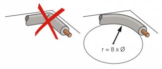
To connect the cable to the power supply for the antenna amplifier, you need to connect the antenna cable to the plug. The first step is to prepare the cable. We retreat one and a half centimeters from the edge of the cable and make a thin circular cut,
Be careful not to damage the fine hairs of the screen under the outer layer of insulation. Remove the cut piece of insulator. Gently and evenly bend the hairs of the screen, it is better to remove the strip of foil. Stepping back 5 mm from the folded edge of the braid, make another circular cut of the inner insulator and remove it. Insert the cable under the fasteners and tighten the screws.
Please note that the metal braid must touch the bottom tinned area, otherwise power may not be supplied to the antenna. Do not allow the braid of the central core to touch, there will be a short circuit and the 12 V indicator light will not light up
If the power supply for the antenna amplifier is correctly connected to the cable, as well as the cable to the antenna amplifier, then the TV will start showing immediately after setup.