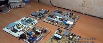
TV repair According to statistics from service centers, failure of power supplies is the most common cause of TV malfunction. Modern televisions use switching power supplies of various designs and circuit designs. However, most of the inherent malfunctions are similar, so the method of dealing with them can be used in different TV models.
Let's look at common device malfunctions related to the operation of the power supply, their external manifestations, as well as solutions.
The fuse blows when you turn on the TV.
This malfunction may be caused by the following reasons:
- Problems in the kinescope demagnetization system;
- Malfunctions of the surge protector and rectifier;
- Failure of the transistor switch.
- To find the cause of the problem, first of all, we check whether there are any traces of a short circuit in the elements of the surge protector and the power supply rectifier.
- Then we check the serviceability of the thermistor (posistor), which is responsible for the correct operation of the screen demagnetization system.
- We make sure that the transistor switch and all elements of its wiring work correctly. If the power supply is built on a key chip, then we check its serviceability.
In this case, it is not enough to simply find the failed element. It is important to find the cause of the malfunction. For example, a malfunction of a key transistor can be triggered by a sharp drop in voltage in the power supply network or failure (drying out) of electrolytic capacitors of the primary circuits.
Monitor stopped working
In the case when even several lamps in it have burned out, and not just one, the screen can be restored. Repair is possible for the following problems with the matrix:
— gray screen; — hazy image; — vertical stripes appeared; — the image slows down; - splitting of moving objects.
All the TVs that we listed above differ only in the backlight. However, they do not have any fundamental distinctive characteristics.
Please note that in LED models the monitor can be backlit using LEDs. And in LCD TVs - using fluorescent lamps. That's why when your monitor breaks down, the first thing you need to do is check the backlight power supply.
What do they do in this case? The device model may vary. Despite this, you need to remove the back cover and power cables from the matrix. Before doing this, of course, you need to disconnect the device from the power supply. Need to check if the wires are working? To do this, it will be enough to connect an ordinary lamp to them.
IMPORTANT! Please note that in most cases, modern TVs often have several backlight sources. And therefore they will need to be checked each separately.
Testing the matrix assumes that a lamp will be connected to the contacts and the wire will be connected to the network. When everything is in order, the lamp lights up. If there is a malfunction, the cable will have to be replaced. Or you will need to restore individual threads.
The power supply is not functioning, the mains fuse is OK
In this case, suspicion may fall on the network filter, rectifier elements and PWM (pulse width) modulator, which should be checked for a break.
- Let’s make sure that a constant voltage (approximately 300 V) “hangs” on the network capacitor. If there is no voltage, then you should look for a break in the surge protector or check the serviceability of the resistor.
- We check whether the voltage reaches the transistor switch. We make sure that there is no break in the primary winding of the pulse network transformer.
- If no faults are found, we check whether pulses are sent to the gate of the transistor operating as a key.
- It doesn’t hurt to check the serviceability of the starting resistor, which usually has a high resistance rating.
The indicator flashes in a certain sequence
Television receivers from some manufacturers: Sony, Philips, Panasonic provide self-diagnosis of the TV when it is turned on. As a result of polling on the SDA and SCL buses, the central processor receives information about the performance of other functional devices: tuner, sound processor, memory chips, the digital bus itself, etc. If a faulty node is detected, the turn-on command is blocked, and the receiver goes into standby mode with error indication. The light indicators begin to blink in a certain sequence, indicating a particular error in the device.
This method of self-diagnosis allows you to quickly identify a faulty component. The service instructions for a specific model contain so-called error codes, in which each combination of blinking indicators corresponds to possible failures of various components of the television receiver. This makes life much easier for the telemaster during diagnostics, guiding him along the right path. For example, 13 LED blinks after a pause on a Sony TV on the FIX2 chassis indicates problems with the backlight. The inverter or lamps may be faulty, so we will diagnose them. As an example, I will give a table with error codes for Philips TVs on the Q552.1E LA chassis. We see the first level of errors (Layer 1) immediately when a defect occurs, the second level (Layer 2) can be observed if the receiver is switched to service mode.
To summarize, we can say that the behavior of the indicator light on a TV when a malfunction occurs can provide a lot of useful information for successful diagnosis and localization of the defect in a particular unit as a whole.
Share on social networks
The power supply protection system is triggered
In this case, you should check the serviceability and absence of short circuits in the secondary rectifiers and power supply loads, as well as in the protection systems (output voltage level control circuits) and feedback (modulator).
In rectifiers, special attention should be paid to the serviceability of diodes and filter capacitors, and in the protection system, it is necessary to check the serviceability of the optocoupler and its accompanying elements (piping).
In feedback circuits, capacitors, zener diodes and diodes are subject to testing.
Fuse blown
We draw the attention of those who are planning to replace the fuse that only in ten cases out of a hundred does the device begin to function again after this.
Such repair of LED TVs will not be possible if you do not have tools such as:
- microscope; - tweezers; — incisors; — soldering iron with a set of tips; - special meter.
Without the listed set, there will be no way to replace such an important element for the operation of the TV yourself. After all, he is fragile and small.
The voltage at the output of the power supply is not normal
In this case, it is necessary to check the serviceability of the network capacitor, elements that ensure the operation of the PWM modulator and the protective optocoupler.
If problems occur periodically in the power supply
To find the causes of the malfunction, use the following algorithm:
- Carefully examine the soldering areas of the power supply elements for the presence of circular cracks;
- Find elements in the power supply circuit with a blackened body, which indicates overheating;
- If the malfunction begins to appear only after the TV has warmed up, then you can determine the culprit element by artificially cooling it (wetting it with alcohol or acetone) or heating it (with a soldering iron). The behavior of the power supply in this case can significantly narrow the scope of troubleshooting.
Do-it-yourself CRT (picture tube) TV repair
Television receivers confidently occupy one of the leading places in use among other household appliances. They are used by all family members, both for educational purposes and for entertainment. One family may have several televisions. In the living room, kitchen, bedroom and so on.
The popularity of these devices is explained by the presence of a large screen, which, compared to monitors, provides more comfortable viewing of video content.
In addition, not everyone loves and knows how to use a computer, especially older people. Therefore, with the advent of the Internet, televisions still remain popular among different ages and segments of the population.
Like any household appliance, televisions break down sooner or later. Therefore, it would be useful to know the causes of breakdowns of these devices in order to prevent them, and if this does happen, try to repair the device yourself.
I would like to note right away that a TV is a very complex and fragile household appliance. It should be handled very carefully. This is due to the fact that it has a picture tube or liquid crystal panel, which can be damaged if handled carelessly and then replacing them can cost 70% of the cost of the TV itself. Therefore, you need to be extremely careful with them.
As mentioned above, there are two main types of TV screens. This is an electron beam tube (CRT or kinescope) and a liquid crystal panel.
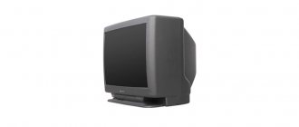
Rice. 1. CRT TV, which I will repair
A ray tube is essentially a large vacuum tube, inside of which there is a vacuum and in which the beam draws an image using deflecting horizontal and vertical coils. Due to the fact that it has an elongated shape, the thickness of the TV is quite significant.
Liquid crystal panels lack all this. The panel itself is a set of LEDs of three primary colors and located next to each other.
The image is obtained by applying voltage to each LED from the video processor and, depending on its value, different colors and shades are formed on the screen. The use of liquid crystal panels has significantly reduced the thickness, weight, and power consumption of such televisions.
We can say that these are completely different devices in design. The only thing they may have in common is the receiving part, the circuit responsible for sound and controls.
In this article we will talk about repairing a TV with a cathode ray tube or picture tube, since they are still actively used, and there is a better chance of repairing such a device than a liquid crystal one.
But when repairing such devices, you need to be very careful, since they contain high voltage up to 25 thousand volts, which are necessary for the operation of the kinescope. This is indicated by the warning signs affixed to the inside of the kinescope. This voltage may remain on the handset even after the TV is unplugged.
Therefore, you should be careful and attentive so as not to receive a life-threatening electric shock. But more on that a little later.
Let's look at the “symptoms” of a breakdown of the Rolsen TV model C29R70T.
It is worth noting that this receiver is assembled from components from Samsung and Philips, which indicates a similar circuit design for other TVs of this type. This means that both the causes and the repair of devices from other companies will be carried out using the same method as here.
And so, let's move on to the breakdown itself, namely, how it manifests itself (see Figure 2). At first the TV worked fine, but periodically the image disappeared, the screen turned black, and there was a white horizontal stripe in the middle. However, sound, remote control and other functions worked fine.
Rice. 2. White horizontal stripe on the CRT TV screen
Also, no extraneous sounds in the form of crackling or burning odors were observed.
Over time, the image disappeared completely, and instead of it, there was always a light stripe in the middle of the screen. It is noteworthy that if you tap on the body of the TV, the band expands abruptly, synchronously with the blows.
Everything indicated that there was no good contact somewhere. Now I had to find where.
It is very important to identify a possible breakdown by “symptoms” in order to limit the search area and not waste time on the working components of the TV. Moreover, unnecessary disassembly, rotation of the board and removal of connectors can lead to even greater problems than before.
For example, some wire may break, and there is also a danger of “destroying” one of the fragile radio components on the board with your hands or a screwdriver.
Therefore, it is very important to carry out a preliminary diagnosis whenever possible.
Whatever it is, the TV will still have to be disassembled. Therefore, we proceed to dismantling the rear protective cover.
To determine where the fastening screws are located, you need to carefully inspect the cover from all sides. The screws may be so hidden that you may not notice them right away. And one unscrewed screw will prevent the lid from coming off, and in doing so, you can break the attachment point.
Rice. 3. Unscrew the fastening screws
When moving or turning the TV, do not shake or hit it too much. This can lead to a break in the filament in the kinescope bulb, which will lead to its failure and there is no point in repairing the device further. Of course, with a cold spiral this happens extremely rarely, but sometimes it happens.
So, the screws have been found, all that remains is to unscrew them. As you can see, the screws may be in hidden places.
Rice. 4. Unscrew the screw in a hidden place
One of the most inconvenient was in the lower part, under the TV. To get to it, you need to lift the back of the case and unscrew the screw. It is better to do this together, so that one person holds the TV, and the other person unscrews the screw.
The fact is that the front part, where the kinescope is, weighs three times more than the back. Therefore, when you try to tilt the TV from behind alone, it may tumble forward so that you do not have time to do anything.
If you still haven’t found a partner, then you can put several heavy books in front. This will give the TV a rest when trying to tilt it.
Rice. 5. Screw at the bottom of the TV
When all the screws around the perimeter of the cover are unscrewed, we try to pull it back. To make it come out of the grooves better, the TV needs to be tilted slightly forward.
Rice. 6. Pull off the TV cover
When removing the cover, make sure that it does not change its direction of movement. If it is sharply pulled to the side, it can break the kinescope bulb on which the board with the elements is installed.
Rice. 7.
Rice. 8. We get access to the kinescope
The flask in this place is very fragile and has a significant narrowing. Also, when the lid is already removed, you need to be careful not to hit or snag this flask.
Rice. 9. CRT TV bulb
There is no need to touch or move the beam deflection adjustment levers, otherwise the image may not be clear later, and it will not be possible to return them to their original position without special devices.
Remove the lid and put it aside. When viewed with the naked eye, you can see how much dust is inside, both on the case and on the boards. If possible, it should be wiped off. Such dust becomes conductive and can cause short circuits and even fire.
Rice.
10. Wipe off the dust Due to the high voltage inside, all the dust from the room is attracted and settles near the elements of the high voltage converter.
Rice. 11. Dust inside the TV
Over time, current may shoot through it into the TV chassis. Therefore, dust must be removed. Even the manufacturers themselves recommend doing this at least once a year.
Take a rag and wipe the body both outside and inside.
You can see how much dust has accumulated on the surface over a couple of years of work.
Rice. 12. Dust on the surface of the board
It is also advisable to clean the board (see Figure 13). But not with a damp cloth, but with cotton wool soaked in alcohol.
When the cotton wool becomes dirty, it needs to be changed. This can also be done with a vacuum cleaner with a special brush attachment. In any case, you need to clean the boards carefully and slowly so as not to break anything.
Without dust, the board will cool better, which will prolong the life of its components.
Rice. 13. Cleaning the board from dust
Let's move on to troubleshooting. It is necessary to inspect the main board for burnt tracks and electronic components. To understand where to look for a fault, you need to know what conventional blocks the “stuffing” of the TV consists of, and which components are responsible for what.
The latest models of CRT televisions are built on a single-chip processor. These are mainly chips from Philips. The signal from the antenna input goes to the channel selector, where it is converted.
Rice. 14. Single-chip processor TDA9351PS/N3/1/1758
Next, the signal, after passing through some filters, arrives at this single-chip processor. Signals from the “tulip” and Scart connectors also come there.
Rice. 15. TV selector KS-H-148
It is processed and divided into audio, video signals and pulses necessary for the operation of the kinescope scan. Each signal comes out from a specific processor pin.
Further, it is either amplified using special microcircuits, or goes directly to the actuator.
The following signals can be amplified: low frequency (sound), video signal, vertical and horizontal scanning pulses. Each signal has its own amplifier, most often built on a microcircuit. Therefore, it’s a good idea to have a schematic diagram of a TV, which can be found on the Internet.
Rice. 16. Electronic filling of the TV board
Using Yandex search, you can determine which microcircuit is responsible for what.
This will make it easier to find the cause of the breakdown, paying special attention to the components of the corresponding unit.
Let's go back to our TV. Let's do a fault analysis. There is sound, the channels are switched, which means: the power supply, tuner, processor and sound amplifier are in order.
Please note that there is a horizontal stripe in the center on the screen. This indicates that the vertical scan is not working properly.
If the strip were vertical, attention would need to be paid to the horizontal scanning elements and the high-voltage transformer.
And so, the problem is the small amplitude of the vertical scanning signal. This signal is too small to sufficiently deflect the electron beam by the frame coils.
This means that the problem is most likely in the amplifier of this signal. Using a circuit found on the Internet for this TV, it was determined that this is a TDA8359J chip. It has nine pins and is located on a common radiator - heat sink.
On the board it is designated as D600.
Rice. 17.
Rice. 18.
Rice. 19. TDA8359J chip (D600 on board)
Perhaps it has failed, or its wiring - resistors and capacitors. We carefully inspect the microcircuit itself and nearby elements for discoloration or swelling. Nothing like this is visible.
Next, pull the board closer and turn it over. The traces and soldering points are visible here. For a good result, it is advisable to use a table lamp and a magnifying glass.
Rice. 20. Board on the reverse side
Also, you should be careful not to touch the solder joints of the high-voltage electrolytic capacitor, so as not to get discharged.
You can short-circuit the terminals of the capacitor with a screwdriver to remove the charge and work quietly.
Upon careful examination, through a magnifying glass, of the soldering joints of the legs of the D600 microcircuit, a defect was found in the form of a tin crack around the pin of the microcircuit (see Figure 21). It is very difficult to notice, especially with the naked eye.
Rice. 21. Place for soldering the legs of the D600 microcircuit
This defect is very common in various techniques. The reasons are: low quality tin, thickened legs of the part and significant heating during operation. It’s not for nothing that this chip has a heat sink.
Another reason may be vibrations and the thin fiberglass from which the board is made. The manufacturer saved on the thickness of the material, but in the end we have this problem. The board really bends easily, which leads to solder cracks, peeling of tracks and other defects.
The way out of this situation is to carefully solder all the legs of the microcircuit. Be sure to use flux when soldering. Do not use acid under any circumstances, but only rosin.
You can solder the legs of other power microcircuits and massive components.
Soldering processor pins unnecessarily is not recommended. Since they are too close, they can easily overheat, or the legs can be shorted together. Then it will be very difficult to get everything back.
After soldering, use a knife or something sharp to remove possible microconnections between the board tracks, especially where the work was done.
We install the board back and try to turn on the TV. It is advisable to put on the cover, taking care not to damage the kinescope, while holding the Scart connector from behind so that the board fits into the seats.
Rice. 22. Install the board back
As you can see in the photo, the picture expanded to the full height of the screen and this means that the problem was precisely in the cracks in the solder legs of the vertical scanning chip.
Rice. 23. The picture is displayed well, the TV works!
Now you can screw the cover on and continue using the TV.
Frame scanning defects
Samsung SCT11D. Strong twist of the frame from above. Zener diodes DZ301 and DZ303 (33v and 22v respectively) are broken.
SAMSUNG chassis SCT11B came with a faulty TDKS. After replacing it with a new one, horizontal scanning started, but not frame scanning. The TA8445K turned out to be operational, there are no startup pulses. On the VPG101T ceramic assembly, the first transistor turned out to be broken (in a working VPG, a resistance of 100 kOhm is measured between legs 1 and 5 with a digital multimeter, and in the diode test mode, the base-emitter junction of the first transistor is measured). After replacing C1Y on the assembly with a regular PNP transistor, it turned out that the vertical scan trigger pulses do not come from the 18th leg of the M52309SP. I did it as in secret No. 325, started the personnel one from pin 19 of the M52309SP, and everything worked. Two transistors and a resistor solved the problem of replacing the M52309SP and VPG101T.
SAMSUNG CK-5051(P68SA chassis). Defect: periodically does not turn on from standby mode; when you press the CH buttons, quiet clicks are heard. Malfunction: capacitor C855 dried out (after desoldering, traces of electrolyte were found under it), which led to a drop in the supply voltage at the moment of switching on from the container. mode.
Samsung CK5366. There is no frame scan. Blame the krenka - 1С805.
Samsung CW28C73W. Chassis KS3A. Received for repair with a defect: periodic disappearance of the image. Checking the V-SYNC and H-SYNC pulses showed that at pin No. 11 of the VDP3120B the H-SYNC amplitude is only 2 volts. At the same time, the constant voltage mode was overestimated - about 3V. The fault is with D203 (RB441Q), the reverse current of which periodically increased and then disappeared.
SAMSUNG CK-5373 does not have a raster, there is sound for all programs. According to the owner, it broke down with a howl when the heater was turned on in the tee, where the TV was already turned on. When adding SCREEN, a raster with noise appeared, but there are graphics. In the tuning mode, you can hear from the sound that the programs are being tuned on all ranges. After replacing the 24C04 memory, everything worked even without adjustment in SERV. Along the way, a defect with which the owner had been putting up with for probably a year was eliminated in the same device. The strong curl from below in the frames with warming up decreased, but was not completely eliminated. C303 2.2 µF on the fifth pin of TA8445K.
SAMSUNG CK-564BZR, The screen is dark, there is OSD and sound. AT pin 22 of the TDA 8844 the voltage is 0 V. Leakage in C255 (0.1 µF). After replacing the C255, the image appeared. Samsung CK-5385ZBR after a thunderstorm. The power supply is live, there is no +5V on the SZM-137M3, the processor itself shorted. I changed it, the TV turned on, but there was no frame. I looked at it with an oscilloscope - indeed, on the 18th leg of the M52309SP the pulses are greatly underestimated. I used the 19th - it didn’t help, VPG101 also crashed. I replaced it, the scan appeared, but the image rattled vertically. I had to change M52309SP as well.
SAMSUNG CK-5373ZR screen is pressed from bottom to top white stripes - replace C308 3.3X50V
SAMSUNG CK-564BZR, The screen is dark, there is OSD and sound. AT pin 22 of the TDA 8844 the voltage is 0 V. Leakage in C255 (0.1 µF). After replacing the C255, the image appeared. Samsung CW-5083V. There is sound and TV control. No raster. Line scanning is all normal. Added SCREEN - a narrow, horizontal, bright stripe appeared in the center of the screen. There is no frame scan. CR launch pulses are present. At 41 pins of the TDA8362B there is 4.6V. By pin 41 of the TDA8362B, the video path is locked in the event of a malfunction of the control system, when on pin 41. the voltage becomes less than 1V or more than 4V.