In an area of uncertain reception of a television signal, in order to obtain a high-quality picture when watching television, you have to install an external antenna on the mast, on the vibrator of which an antenna amplifier is additionally installed. Installing an additional amplifier ensures a high-quality picture on the TV when the TV transmission tower is up to 100 km away.
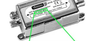
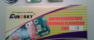
Antenna amplifiers of the SWA line have become widespread due to their high reliability and low price. They are produced for different channel ranges and different gain factors, from 34 to 43 dB in the UHF range and from 10 to 15 dB in the meter range. The photo shows an amplifier type SWA-555/LUX.
The SWA television signal antenna amplifier must be powered with a constant voltage of 12 V. There is a circuit solution that allows supply voltage to the television amplifier via a coaxial cable simultaneously with the television signal. The photo shows how to connect a television wire to the SWA antenna amplifier.
The central core is clamped with one screw, and the shielding wire is stripped of insulation, wrapped and clamped with screws using a strip. The main thing here is to prevent the screen wires from shorting out with the central core. In this way, antenna amplifiers of any type installed directly on the antenna are connected.
There are special power supplies on sale - adapters with adapters that allow you to supply power to the antenna amplifier. The photo shows one of them. Connecting such an adapter is simple; the cable coming from the antenna is inserted into one coaxial wire, and the cable going to the TV is inserted into the second. The adapter itself is plugged into the socket. It is impossible to mix up the wires when connecting; the coaxial wires coming out of the adapter have different connectors, which prevents erroneous connections.
Power supply - adapter for antenna amplifier
If you open any power supply with an adapter, you will see a power transformer, four diodes, an electrolytic capacitor, a simple capacitor, a choke and a voltage stabilizer microcircuit.
All parts of the decoupling circuit, except the power transformer, are installed on the printed circuit board.
Electrical circuit diagram of the power supply for the antenna amplifier with adapter
The power supply shown above in the photo - an adapter for powering the antenna amplifier - is assembled according to a classic electrical circuit diagram. AC mains voltage 220 V is supplied to power transformer T1, which lowers it to 12-15 V. The diode bridge VD1-VD4 rectifies the voltage, the electrolytic capacitor C1 smoothes out the ripples, after which a constant voltage of about 16 V is supplied to the integrated voltage stabilizer DA1.
To eliminate video signal losses and loss of DC voltage, an LC filter is provided at the input of the television receiver, made on elements L1 and C3. Choke L1 does not pass a high-frequency television signal to the power supply circuit, but without losses it allows direct current to flow to the central core of the television cable coming from the television antenna amplifier. Capacitor C3 prevents DC current from flowing from the power supply to the TV input, but passes the TV signal without loss.
When making your own power supply with an adapter, parts can be used of any type. Typically, the current consumption of antenna amplifiers does not exceed 150 mA, which is less than 2 watts, so the transformer for the power supply is suitable for any power with an output voltage of 15-18 V. The choke can be made by winding it on a dielectric base, for example, a strip of fiberglass 5 mm wide, 25-18 V. 30 turns of enameled copper wire with a diameter of 0.1-0.5 mm.
Disadvantages of the presented design of the power supply with adapter
The disadvantages of a power supply adapter of this design include the presence of an unshielded section of the central core of the television cable at the place where it is sealed into the printed circuit board, which, in the presence of interference, for example from a working vacuum cleaner, can lead to interference with the video signal. The penetration of interference can be eliminated by installing an additional shield on the printed circuit board at the place where the wires are soldered.
Which antenna to choose for receiving television broadcasts
Television broadcasting is mastering the UHF range (300 - 900 MHz), horizontal polarization is used. To fish, take the trouble to find a paraboloid with a correctly configured feed; you will need direct visibility to the television center or precise adjustment to the reflected signal, which is changed by weather conditions, even by the wind. It is not customary to use paraboloids when receiving terrestrial broadcasts. The satellite hangs inexorably in one place, the positioning point is periodically adjusted by ground stations, you can get by with a dish. Naturally, direct visibility must be present.
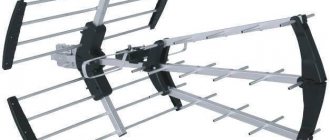
Among the many devices, a do-it-yourself outdoor television antenna is easier to assemble using the wave channel type (Udo-Yagi antenna). The device has excellent characteristics; today we will consider this class of devices for receiving television broadcasts.
Design and diagram of the crab
The TV crab is a metal box with F-connectors. Inside, on the central terminals of the connectors, parts (high-frequency transformers) of the television signal splitter are soldered. A high-frequency transformer is shaped like a ring or tube made of ferrite with a magnetic permeability of 600-2000, on which 1 to 10 turns of enameled wire with a diameter of 0.2-0.3 mm are wound, evenly spaced around the entire circumference.
In the photograph of the crab from which the back cover has been removed, you can clearly see how the ferrite transformers are wired for connecting three TVs. This crab is assembled according to the Electrical Circuit Diagram below.
All produced crabs are assembled according to the given electrical circuit diagram; there may be minor deviations - additional separating and filtering capacitors, chokes, and matching resistors are installed.
Antenna at 855 Hertz
According to estimates, the size of the antenna will correspond to the European 69th channel, which includes Russia. Television is shown at a frequency of 855.25 Hertz, and sound is shown at 861.75 Hertz. According to calculations, its antenna circuit is tuned to 857 Hertz. The design will require a large piece of 75 ohm cable. We make a ring with a gap from 54 centimeters, we will take a signal from it
Please pay special attention that the screen in this version is a signal one. We attach a matching U-elbow made of 75 Ohm wire to it, the size of half a wave – 175 millimeters
It goes like this:
- one end of the core inside the U-elbow wire is seated on the signal wire connected to the receiver and on one of the parts of the screen;
- the other end of the U-elbow wire strand is seated at the other end of the screen.
As a result, the added part of the line equalizes the resistance of the wire connected to the receiver and the circular circuit. In order to make a UHF digital antenna from this design, it must be adjusted to the multiplex frequency
. How to do this is probably already clear, but we will describe in detail:
- The size of the U-elbow is half the size of the multiplex wave.
- The frame size is equal to ¼ multiplex wavelength.
The multiplex wave size can be found on the Internet or local publications. To obtain vertical polarization, the frame must be rotated at a right angle with a gap to the side. In this case, you can also catch the signal from walkie-talkies. These are the simplest external antennas.
How to make your own adapter for supplying power to an antenna amplifier
When making an adapter for supplying power to an isolated antenna amplifier, I decided not to install an additional connector for connecting the power supply, but to use one of the connectors for connecting the F-plug. To do this, we had to remove one of the transformers, limiting the crab's ability to connect only two TVs.
As a result of the modification, only two TVs can be connected to the crab, and its circuitry has changed.
All that remains is to install the LC filter in the crab and the adapter will be ready for use. Since the crab body is made of duralumin, the capacitor lead had to be connected to it through an additionally installed brass terminal, screwed to the adapter body using a screw and nut with a shaped washer.
As a result of the modification, the electrical circuit diagram of the crab acquired the following form. As can be seen from the diagram, transformer T1 remained original, but a choke and two capacitors were added.
To better match the circuit, you can solder a 150 Ohm resistor between the output pins XW2 and XW3. You can install the adapter in any convenient place, directly next to one of the TVs, or, for example, at the cable entrance to the apartment. If you need to connect only one TV, then transformer T1 can be removed, and the right terminal of capacitor C1 can be soldered directly to the central terminal of one of the connectors XW2 or XW3, to which the cable going to the TV can be connected.
How to boost the signal
Deterioration of the cable TV signal in an apartment occurs for various reasons:
- Poor choice of TV antenna.
- The house is located far from the repeater.
- Lots of natural noise.
- The antenna cable has failed.
- The transmitter is not configured correctly.
- Old technology is used.
To increase communication, you need to use one of the proven methods.
How to boost your TV antenna signal:
- The first step is to change the location of the antenna. It must be directed exactly towards the TV tower.
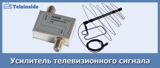
- Buy a good TV antenna signal amplifier. This is an electrical device that connects directly to the device.
- Increase the number of antennas on the roof to achieve a clear image. Each device must be placed in the highest place in the house.
- Replace the antenna with a more powerful analogue.
- Reception may be interfered with by various metal parts that come along the way. Therefore, it is advisable to remove all these items so as not to disrupt the connection.
- If the antenna cable fails, then the quality of the signal is out of the question. If there are problems, you need to check it. In case of a short circuit or break, you will need to buy a new sample.
- Use the effect of a common-mode antenna array. Several receivers are used to create a complex system so that the total load on the phases is uniform.
These are the main ways to improve antenna reception. One of the most effective is to use an amplifier.
Connecting the power supply to the adapter
Since I decided to connect the power supply to the crab through one of its F-connectors, to implement this idea I had to make an adapter from an ordinary double wire coming from the power supply to a coaxial cable.
To do this, you need to take a piece of antenna cable 5 cm long, cut one end of it and put on an F-wrap. To the second end, as shown in the photographs, solder the wires coming from the power supply with a shift. The positive terminal is soldered to the central core of the antenna cable.
If you don’t want to mess around, you can install a standard connector in the crab body for connecting power supplies and through it supply voltage to the antenna amplifier through a home-made adapter.
Satellite TV
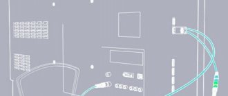
In order for the antenna amplifier installed in the “Polish Grid” antenna housing to work, it must be connected to a power source. The amplifier is powered via a coaxial cable running from the antenna to the TV. This means we need to connect the power supply to this cable. Many users find it difficult to do this. Let's consider a simple connection option.
| The power supply is a converter of high voltage household electricity to low voltage. This voltage is used to provide power to the electrical circuit components. It also serves to stabilize and protect the supply voltage. |
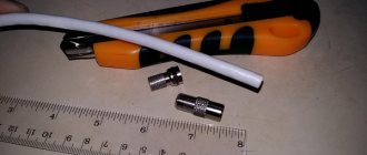
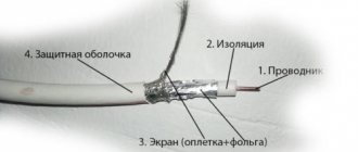
First you need to cut the end of the television cable (more about cutting the cable). We step back 1.5 cm from the end of the cable and carefully remove the outer insulation, trying not to damage the screen and the insulation of the central core. Remove the outer shell cut in a circle. Then we move the hairs of the screen and the foil back. Next, we retreat 0.5 cm from the moved braid and cut off the inner insulation from the central core in a circle. The cable is ready for connection.
Carefully place the cut cable into a special fastener on the power supply separator board. It is necessary that the cable braid tightly touches the lower contact pad, and the central core is inserted into the screw retainer.
We tighten the screws until the cable contacts are completely fixed.
| It is necessary to ensure that the central core and the braid do not touch under any circumstances, otherwise we will get a short circuit and the system will not work. In this case, the indicator on the power supply will light very dimly or not light at all. You also need to ensure that the braid is in close contact with the pad on the board. Otherwise, the voltage may not flow through the cable. |
If connected correctly, the TV will begin to show channels when scanning and tuning them. If you turn off the power supply, the image may deteriorate or disappear altogether.
Happy connection!
9, total, today
Please give us your valuable comments
digitalsattv.ru