In an area of uncertain reception of a television signal, in order to obtain a high-quality picture when watching television, you have to install an external antenna on the mast, on the vibrator of which an antenna amplifier is additionally installed. Installing an additional amplifier ensures a high-quality picture on the TV when the TV transmission tower is up to 100 km away.
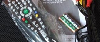
Antenna amplifiers of the SWA line have become widespread due to their high reliability and low price. They are produced for different channel ranges and different gain factors, from 34 to 43 dB in the UHF range and from 10 to 15 dB in the meter range. The photo shows an amplifier type SWA-555/LUX.
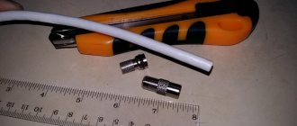
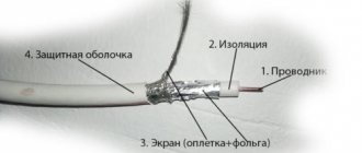
The SWA television signal antenna amplifier must be powered with a constant voltage of 12 V. There is a circuit solution that allows supply voltage to the television amplifier via a coaxial cable simultaneously with the television signal. The photo shows how to connect a television wire to the SWA antenna amplifier.
The central core is clamped with one screw, and the shielding wire is stripped of insulation, wrapped and clamped with screws using a strip. The main thing here is to prevent the screen wires from shorting out with the central core. In this way, antenna amplifiers of any type installed directly on the antenna are connected.
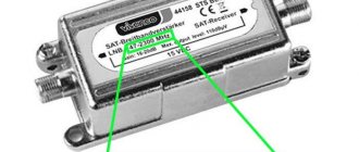
There are special power supplies on sale - adapters with adapters that allow you to supply power to the antenna amplifier. The photo shows one of them. Connecting such an adapter is simple; the cable coming from the antenna is inserted into one coaxial wire, and the cable going to the TV is inserted into the second. The adapter itself is plugged into the socket. It is impossible to mix up the wires when connecting; the coaxial wires coming out of the adapter have different connectors, which prevents erroneous connections.
Power supply - adapter for antenna amplifier
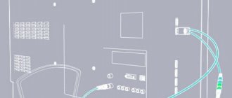
If you open any power supply with an adapter, you will see a power transformer, four diodes, an electrolytic capacitor, a simple capacitor, a choke and a voltage stabilizer microcircuit.
All parts of the decoupling circuit, except the power transformer, are installed on the printed circuit board.
Electrical circuit diagram of the power supply for the antenna amplifier with adapter
The power supply shown above in the photo - an adapter for powering the antenna amplifier - is assembled according to a classic electrical circuit diagram. AC mains voltage 220 V is supplied to power transformer T1, which lowers it to 12-15 V. The diode bridge VD1-VD4 rectifies the voltage, the electrolytic capacitor C1 smoothes out the ripples, after which a constant voltage of about 16 V is supplied to the integrated voltage stabilizer DA1.
To eliminate video signal losses and loss of DC voltage, an LC filter is provided at the input of the television receiver, made on elements L1 and C3. Choke L1 does not pass a high-frequency television signal to the power supply circuit, but without losses it allows direct current to flow to the central core of the television cable coming from the television antenna amplifier. Capacitor C3 prevents DC current from flowing from the power supply to the TV input, but passes the TV signal without loss.
When making your own power supply with an adapter, parts can be used of any type. Typically, the current consumption of antenna amplifiers does not exceed 150 mA, which is less than 2 watts, so the transformer for the power supply is suitable for any power with an output voltage of 15-18 V. The choke can be made by winding it on a dielectric base, for example, a strip of fiberglass 5 mm wide, 25-18 V. 30 turns of enameled copper wire with a diameter of 0.1-0.5 mm.
Disadvantages of the presented design of the power supply with adapter
The disadvantages of a power supply adapter of this design include the presence of an unshielded section of the central core of the television cable at the place where it is sealed into the printed circuit board, which, in the presence of interference, for example from a working vacuum cleaner, can lead to interference with the video signal. The penetration of interference can be eliminated by installing an additional shield on the printed circuit board at the place where the wires are soldered.
Checking signal strength
Before installing the splitter on TVs, it is worth checking the quality of the signal transmitted from the antenna. If the signal is uncertain, you will have to install an antenna with an amplifier. A good signal will allow you to use the antenna without an amplifier for two TVs. There are two ways to check the signal:
- On the remote control we find the “INFO” button. With the antenna connected, press this button twice and the signal level will be displayed on the screen.
- On the remote control, press “Menu” and go to the “Manual setting” mode. In the window that appears, enter the channel number that works well in your region. The signal level will be displayed on the screen.
If the signal level is above 70%, then everything is in order and you can connect an antenna to two points without an amplifier. We will look at the connection diagram for a conventional passive antenna and an active antenna with an amplifier.
Design and diagram of the crab
The TV crab is a metal box with F-connectors. Inside, on the central terminals of the connectors, parts (high-frequency transformers) of the television signal splitter are soldered. A high-frequency transformer is shaped like a ring or tube made of ferrite with a magnetic permeability of 600-2000, on which 1 to 10 turns of enameled wire with a diameter of 0.2-0.3 mm are wound, evenly spaced around the entire circumference.
In the photograph of the crab from which the back cover has been removed, you can clearly see how the ferrite transformers are wired for connecting three TVs. This crab is assembled according to the Electrical Circuit Diagram below.
All produced crabs are assembled according to the given electrical circuit diagram; there may be minor deviations - additional separating and filtering capacitors, chokes, and matching resistors are installed.
How to make your own adapter for supplying power to an antenna amplifier
When making an adapter for supplying power to an isolated antenna amplifier, I decided not to install an additional connector for connecting the power supply, but to use one of the connectors for connecting the F-plug. To do this, we had to remove one of the transformers, limiting the crab's ability to connect only two TVs.
As a result of the modification, only two TVs can be connected to the crab, and its circuitry has changed.
All that remains is to install the LC filter in the crab and the adapter will be ready for use. Since the crab body is made of duralumin, the capacitor lead had to be connected to it through an additionally installed brass terminal, screwed to the adapter body using a screw and nut with a shaped washer.
As a result of the modification, the electrical circuit diagram of the crab acquired the following form. As can be seen from the diagram, transformer T1 remained original, but a choke and two capacitors were added.
To better match the circuit, you can solder a 150 Ohm resistor between the output pins XW2 and XW3. You can install the adapter in any convenient place, directly next to one of the TVs, or, for example, at the cable entrance to the apartment. If you need to connect only one TV, then transformer T1 can be removed, and the right terminal of capacitor C1 can be soldered directly to the central terminal of one of the connectors XW2 or XW3, to which the cable going to the TV can be connected.
Types of television antennas
The signal received by the antenna is sent through a coaxial cable to the TV. This ensures a minimum of distortion and more stable operation of the TV receiver. Antennas are used to receive different types of signals:
- analog;
- satellite;
- digital.
The antenna is in great and stable demand in the consumer electronics market. Why? The vast majority of TVs are not capable of receiving a signal without an antenna.
Populated areas are located to varying degrees from relay points. Some are located very far away, while others are very close. This results in the need for antennas, which, compensating for the distance, make it possible to receive a signal of better quality.
TV antennas come in three types:
- indoor;
- street;
- satellite.
Indoor antennas
Installed directly in the room itself. The main advantage of such antennas is that they do not require complex installation. By choosing such an antenna, you will eliminate the need to lay cables outside the room. There will be no need to make holes in the walls, etc.
These devices look different, but they are all united by such features as compactness and low cost.
Indoor antennas
The disadvantage of such antennas is that it makes sense to install them if you are no further than 30 km from the repeater. Any further and the signal will be weak. This problem can be solved by purchasing a signal amplifier or purchasing an antenna with a built-in one (the farther you are from the repeater, the more powerful the amplifier is needed).
There are two types:
Rod.
Users also call them “horns”. These are the weakest devices, but easy to install and compact. The telescopic antennae, which receive the signal, fold up, making the device easy to carry. If the repeater is located nearby, the antennae can be shortened.
Rod antennas are usually sold with the TV. They are connected to a stand with a transformer, which transmits the signal to the TV.
Typical indoor rod antenna
In order to catch the desired channel, you need not only to select the length of the horns, but also their distance from each other. Another disadvantage of this type of antenna is that having caught the optimal signal for one channel, it will not transmit correctly to another.
Frame.
The devices are more reliable than the previous version.
Their outline frame is made of metal and mounted on a stand. Typical indoor loop antenna
In compactness and lightness, loop antennas are not inferior to rod antennas, but the signal is received significantly better. However, if the television tower is far away, such a device will also be of little use.
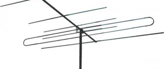
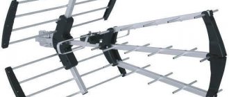
Outdoor antennas
Outdoor TV antennas receive signals more powerfully and with better quality.
Large outdoor antenna
They are installed at elevated locations: on the roofs of high-rise buildings, at the highest points of private houses, etc. This provides the necessary range from interference. It makes sense to install an outdoor antenna 10-15 m higher than the obstacles to the signal (house walls, tree branches, etc.).
Externally, such antennas can differ significantly, but according to the principle of operation they can be divided into only two types:
- active;
- passive.
Active outdoor antennas
Such devices have built-in power amplifiers that can pick up the signal much more efficiently and compensate for interference.
Consider purchasing an active outdoor antenna if:
- the room where you want to tune the TV signal is located far from the repeater;
- there is a significant accumulation of interference in front of the antenna (houses, forests, power lines);
- the room is located in a low area, where there is no direct visibility between the repeater or television station and the point where the signal will arrive.
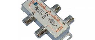
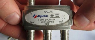
Such antennas are capable of working with several TVs at once. All you need to realize this opportunity is to purchase an additional tee, which is designed specifically for coaxial cable.
Tee for coaxial cable
Amplifiers built into active outdoor antennas require a separate power source. For this, there are special 12-volt step-down units.
12-volt step-down block
The unit is connected to the TV using the same coaxial cable. The voltage supplied by the unit is directed to the receiving point of the antennae-vibrators, next to which there is an amplifier board, closed with a sealed housing.
Passive outdoor antennas
This type of antenna is cheaper, but it makes sense to buy it only when there is direct visibility between the signal reception point and the broadcast point. Because it is in such cases that an outdoor antenna will cope with its task without an amplifier.
For those who live in separate houses located close to the TV tower, the choice of such an antenna will be the most rational. But if the house is too close to the broadcaster, there may also be distortion. In this case, connect an attenuator.
Attenuator - this device will reduce the signal level to the desired level
Satellite dishes
The best option when choosing an antenna would be a satellite one. It picks up the signal not from somewhere on the surface of the earth, where there is a high probability of interference, but from a satellite.
Satellite antenna
The design of such an antenna is quite massive, and its cost is much higher than the cost of more compact and simple devices.
The antenna works by focusing the broadcast with a 3D metal plate. It receives waves that are picked up by a converter (a small part of the dish that tunes to certain satellites, and they, in turn, transmit TV channels without interference or quality defects).
Depending on the region, the number of converters needed may vary, but it is common to find dishes with no more than three converters.
Connecting the power supply to the adapter
Since I decided to connect the power supply to the crab through one of its F-connectors, to implement this idea I had to make an adapter from an ordinary double wire coming from the power supply to a coaxial cable.
To do this, you need to take a piece of antenna cable 5 cm long, cut one end of it and put on an F-wrap. To the second end, as shown in the photographs, solder the wires coming from the power supply with a shift. The positive terminal is soldered to the central core of the antenna cable.
If you don’t want to mess around, you can install a standard connector in the crab body for connecting power supplies and through it supply voltage to the antenna amplifier through a home-made adapter.