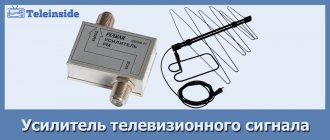
Operating principle of the antenna amplifier
A television antenna signal amplifier is a small device that allows you to create a pulse generated by the interaction of an electromagnetic wave that is more powerful than the one previously received. The antenna adapter works according to the following algorithm:
- An antenna consists of a conductor through which an electromagnetic wave travels (at the speed of light).
- As a result of the passage of the wave, a current pulse appears in the conductor, but it is not sufficient for it to be perceived by the TV or TV tuner that receives the signal.
- The current pulse arrives at the adapter, which records it.
- Using a current of 5 to 12 volts, a copy of the received signal is formed, but with much greater power.
- The high-power duplicate signal leaves the amplifier on its way to the decoder of the TV tuner (external receiver or internal in the TV), which turns it into an audio track and video.
An additional option that the device has is signal filtering. Since in each antenna, in addition to the required range, there are excess currents (interference from various electrical devices around), the device removes unnecessary signals and amplifies useful ones.
Choosing a digital signal amplifier for your TV
There are several criteria by which you should choose an adapter:
- Nutrition plans;
- Frequency range;
- Location.
By nutrition
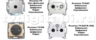
There are three schemes by which you can connect the antenna adapter:
- Using the antenna socket. Digital tuners and TV receivers are equipped with the option of supplying power via a television cable to the amplifier. For this function to work correctly, it must be enabled in the settings of the TV or receiver connected to the TV.
- Via an external power supply. The voltage goes through the same wire through which the signal arrives. The adapter is included with the amplifier.
- From the built-in adapter. The device connects the antenna and the TV with a cable, transmitting only the signal. It itself is connected to a 220V network.
It is not recommended to use more than one power supply circuit, as this may result in signal interruption. There is also a chance that the amplifier unit will fail.
When using an external adapter, do not forget to deactivate the power supply to the antenna socket in the settings of your TV or TV tuner.
By frequency
Amplifiers can use different frequency ranges, therefore they are divided into three types:
- Broadband. They amplify the signal in a wide range of 47-2300 MHz, but the quality of the amplification is poor. This type can be used with any antenna, but it is not considered universal, since uniform gain with wide coverage is impossible, which will result in drops in TV signal quality.
- Range. Specially calculated for a specific wavelength region. For example, the range is 470-870 MHz. Such a device is capable of amplifying and delivering to a TV twenty publicly available digital TV channels, which are broadcast at frequencies of 498 MHz (2 multiplexes, 24 TVCs) and 546 MHz (1 multiplex 30 TVCs). Many people prefer an antenna amplifier for a 20-channel TV.
- Multi-band. Several amplifier blocks connected into one system allow you to work with your own television broadcast zone independently. Covering the entire range is impossible, but there are prerequisites for amplifying both the analog signal (meter range) and the digital signal (UHF). The adapter allows you to set your own coefficient for each channel.
At the installation location
The last stage of separation is the amplifier installation location:
- Built-in. It is part of a single antenna, since it is simply soldered to it. This is similar to using a board mounted inside the antenna housing. The advantage is that the amplifier is 100% compatible with the device that receives signals from the repeater. The downside is that placing the antenna far away from the decoding device may weaken the signal until it reaches the TV tuner. If the casing is not carefully thought out, the amplifier is susceptible to weather conditions.
- External. Paired with passive outdoor antennas. They may differ in appearance and size (for example, a small set-top box or a mortise cable block). A digital TV signal amplifier, regardless of its type, must be interfaced with the input of the receiving device.
Follow one rule when choosing an antenna amplifier for your TV - the gain should not be less than the antenna, otherwise the device will simply be useless. Study the instructions with the technical characteristics of the adapter, read the reviews of the model you are interested in.
Where to point the antenna to receive digital television in the Moscow region
Today we will tell you where, in which direction, to point the antenna to receive 20 channels of free digital television in the Moscow region, how to actually find out where to turn the digital antenna, where the digital TV transmitter is located, and about the digital reception map - location, and coverage area of the digital signal in Moscow region.
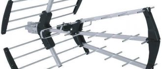
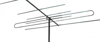
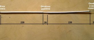
The antenna is designed in such a way that the signal is amplified from one direction and weakened from all others. The reception sector is usually 10-20 degrees; very good antennas can even be 5 degrees. That is, the stronger the antenna, the more accurately it must be directed to the source of the TV signal. Therefore, it is necessary to carefully adjust the antenna to the transmission location - to the TV tower. If you need a powerful antenna, it must be long. The correct maximum length of a passive antenna is approximately 1.3 - 1.5 meters. There are antennas without an amplifier 2-2.5 meters long, but this is necessary for reception from 80-100 km. And by the way, it’s not a fact that everything will work out.
THE AMPLIFIER IS WHAT TURNES A PASSIVE ANTENNA INTO AN ACTIVE!
An active antenna contains an amplifier. And the amplifier gain is added to the antenna gain. That is, if a passive antenna has a gain of 8 decibels, then an active antenna with an added amplifier of 20 decibels will have a total gain of 28 decibels. Channels are transmitted in packets divisible by 10.
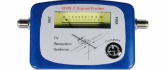
1. In order for the antenna to receive the signal better, it must be directed towards the television tower. The power level and quality of the signal from the antenna must be monitored. To do this, on the remote control of the digital set-top box (receiver) we find the INFO button. Press the button once, twice, third time.
INFO BUTTON ON THE REMOTE CONTROL FOR CONTROL OF DIGITAL SIGNAL LEVEL
Two lines should appear on the TV screen - “Signal Level” and “Signal Quality”. By rotating the antenna, moving it, you need to achieve the maximum value of these numbers. Turn it and wait 5 seconds. Then you turn and see how the numbers have changed. This is how the antenna is adjusted in direction.
Channels are transmitted in packets divisible by 10. This packet is called “Multiplex”. If 20 channels are transmitted, then they are transmitted in two multiplex packages. Data on the power of the multiplex can be found by pressing the INFO button. For example, check the power of the first multiplex on the first channel, the second - on the 11th channel. Multiplexes are transmitted on different frequencies. That is, a group of channels of the first multiplex (from 1 to 10 channels) is transmitted on one frequency, and the channels of the second multiplex (from 11 to 20 channels) are transmitted on a second frequency. If only one multiplex is received, you need to more accurately adjust the antenna in direction, raise the antenna higher, etc.
2. In a SMART TV, information about the signal level may or may not be... or may be missing! Absent completely! Why this is so and which TV has this function is unknown. Ask about this when purchasing.
This is so sad... And it will be better if you set up the TV in advance. Where digital TV reception is fine.
INFORMATION ABOUT SIGNAL LEVEL FROM ANTENNA AND QUALITY IS IMPORTANT
3. Antenna setup.
If the parameters are less than 40-50%, you need to look for a better reception location, install the antenna higher, or buy a more powerful antenna. In our case, everything is quite decent - both the signal intensity and quality are 90% or more.
4. What if instead of 20 free channels, only 10 channels are shown? And the same thing - you need to look for a better reception location, install the antenna higher, buy a more powerful antenna. Channels are transmitted in packets divisible by 10. Each transmitter transmits 10 channels. The power of the transmitters is usually different - and if the antenna is directed slightly in the wrong direction, then only one more powerful multiplex (10 channels) is received. Channels are transmitted in packets divisible by 10. Therefore, it is necessary to carefully adjust the antenna to the transmission location - to the TV tower.
Previously, there was, at best, only one TV transmitter for the entire region. Now the number of stations broadcasting free digital TV has increased hundreds of times. And if previously it was 80 km from you to the transmitter, now most likely it is much less. Again. There are many digital transmitters, do not believe your neighbor who says that he is the only one. You can check it on the website MAP OF DIGITAL TV RUSSIA . Find your location on this map. Then it turns out that there are one, or two, or maybe even three TV transmitters next to you. Raise the antenna higher and point it towards one, or another, or a third transmitter. And control information about the signal level and quality.
Interactive map of CETV - will show how far the nearest TV digital transmitter is from you
For example, from Yegoryevsk you can point the antenna in the direction of three transmitters (see figure). Perhaps there is an obstacle in one direction, or a weak signal in another. Raise your antenna higher and spin it! And information about the signal level will help you make the right decision!
By left-clicking on the point on the map where you need to install an antenna or connect digital television receiving twenty free channels, you will see something like the following picture:
In the table that appears, we see the exact distance to the repeaters and broadcast frequencies.
There is one more nuance - in St. Petersburg, multiplexes are transmitted at frequencies of 586 MHz and 666 MHz. These are pretty close frequencies. If the antenna receives one frequency (multiplex), then most likely it also receives the second multiplex. However, there are also difficult situations, as in Yaroslavl -
In the next article we will talk about Antennas originally from the USSR for receiving digital TV. Back to the Seventies!
How to properly connect an amplifier
The signal should be amplified correctly, based on the instructions:
- Connect the antenna at the minimum accessible distance from the TV. If the signal is within normal limits, then from its gain values you can determine the necessary parameters to output an excellent signal.
- Pair the antenna with the TV, which will be located in the place allocated to it, through an amplifier. The coefficient should be higher than what the antenna produces. If no interference is observed, you can complete the adjustment at this step. If there is no signal, raise the amplifier gain until it is detected.
- If the signal is present, but when amplified they stop broadcasting, or the display shows an overlap of two video sequences on top of each other - turn the amplifier up, make the coefficient smaller to reduce the video broadcast to the required threshold.
Parameters for selecting a digital television antenna amplifier
Surely, if you are already reading this material, then you need a signal amplifier. So we won't go around and start right away. In order to make an informed choice, you need to know the basic parameters of amplifiers and what they are responsible for. Currently, the following characteristics can be distinguished.
- By type of amplification. Broadband. They amplify the signal over the entire frequency range (in meter and decimeter waves).
- Range. They work only in a given interval-sector.
- 12 volt.
- Installation along the antenna contour. Typically, such amplifiers are electronic boards.
Table of amplifier application options.
| Residence area | Antenna gain | Need for an amplifier | Coefficients required amplifier gain |
| Close to the TV tower (up to 7 km) | From 4 dB | No | — |
| At a medium distance (up to 30 km) | From 10 dB | Depends on a situation | — |
| At the border of the signal transmission zone (more than 30 km) | From 12 dB | Yes | 20-30DB |
Rating of the best digital signal amplifiers
There are many amplifier models on the market at affordable prices for consumers.
Gal AMP-102
Wideband TV signal amplifier, which is designed for 1-2 TVs. Works with HF and UHF antennas. The main difference is the weight of 0.2 kg and the rectangular shape. According to the diagram, it is interfaced between the antenna cable and the TV connector, and uses the adapter mated to the plug as power.
ALCAD AL-200
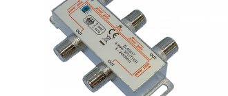
A splitter amplifier with two “outputs” can split an antenna cable into two to split the signal and transmit it to two TVs. The device is multi-band with separate adjustment of stages, gain 24 dB. For splitting on 3-4 TVs, you need to look for more powerful units.
JMA 8620SA3
Broadband amplifier with split into three outputs. You can equip up to three TVs. The metal case provides “iron” protection from damage. Gain: 20 dB.
ALCAD AL-400
Dual-band amplifier for interaction with frequencies 40-318 MHz and 470-862 MHz. It has 4 outputs, and the maximum gain is 28 dB.
homecontacts site map
Detailed recommendations for choosing the type of antenna amplifier can be found here. However, such information is more suitable for persons with some radio engineering training. We will present you with inexpensive and high-quality equipment from our recommended list.
Subscriber amplifiers
Subscriber amplifiers AE-108STm+ , AD 420 Plus DC are designed specifically for the convenience of DVB-T2 reception. The amplifiers are characterized by the feature that they have the ability to supply power to mast amplifiers with a voltage of +12 V. Often in practice this function is very important ( especially for DVB-T2 reception ). In most cases, it is sufficient to use only one subscriber amplifier (i.e. without a mast amplifier). The optimal gain at a sufficiently high output level guarantees the absence of any distortion, and the small dimensions with ease of mounting have ensured high popularity as subscriber amplifiers. They are usually installed near a 220 V/50 Hz power outlet, located as close as possible to the antenna (from the cable outlet).
Subscriber amplifier AE-108STm+ (Telemak, Saratov)
| Price: 26 € | ||
| ||
| Appearance | Functional |
Peculiarities
- UHF band only (for DVB-T2 signals);
- Gain adjustment (10 dB);
- Only 1 entrance (UHF);
- Low noise figure (3 dB typical);
- Availability of two outputs (convenience of simultaneous connection of 2 TVs);
- LED indication of the presence of mains power (~220 V/50 Hz);
- LED indication of power supply to the mast amplifier or active antenna (+12 V/50 mA);
- The presence of a power on/off button for a mast amplifier or an active antenna (for example, Rhombus);
- Relatively high level of output signals in relation to residential wiring (at least 82 dBµV for 60 channels).
- Small weight and size characteristics.
Subscriber amplifier AD 420 Plus DC (“Fagor”, Spain)
| Price: 27.5 € | |
| |
| Appearance |
Peculiarities
- High degree of shielding due to metal housing.
- The presence of a switching power supply reduces consumption and internal temperature and thereby increases the service life of the amplifier.
- Modern design and small size (107x48x138 mm) greatly facilitate installation.
- Independent gain control in the UHF and MV ranges.
*) At the Customer's request, it is possible to supply the amplifier in the absence of +12 V power supply (mod. AD 420 Plus).
Technical parameters of subscriber amplifiers
| Options | AE-108STm+ | AD 420 Plus DC/AD 420 Plus |
| Price, euro | 26 | 27,5/27 |
| (Saratov) | Fagor (Spain) | |
| Operating frequency range, MHz | 470-862 (UHF) | 40-318 (MV) 470-862 (UHF) |
| Number of inputs/outputs | 1/2 | |
| Gain, dB | 22 | 28 (MV), 22 (UHF) |
| Max. output level (IMD3=60 dB, 2 channels) | 2x98 | 2x100 |
| Noise figure, dB | 3,5 | 7 (MV), 5 (UHF) |
| Power supply to the mast amplifier, V | +12 | +12/- |
| +12V remote power button | There is | No/- |
| Maximum load current, mA | 50 | 100/- |
| Overload protection | There is | double protection (input + power supply) |
| Type of RF connectors | F-type (75 ohm) | |
| Supply voltage, V | 187…242 V/50 Hz | |
| Power consumption, W | 4 | 1,5 |
| Dimensions, mm | 130x72x44 | 107x48x138 |
Mast amplifiers
Mast amplifier AA-102V4.5 (+12 V)
| Price: 9.6 € |
Ideal solution for most practical applications due to very low noise figure (2 dB), low gain (16 dB) and low cost. The amplifier already has a UHF band filter (470-862 MHz) built into it. The amplifier is powered via a reduction cable from the subscriber amplifier AE-108ST+ or AD 420 Plus DC . Thus, no additional devices in the form of power supplies are required.
UHF mast amplifiers FT series (+12 V)
| FT 21-69 | FT 21-69 DELTA |
| Price: 7 € | Price: 8 € |
Mast amplifiers of the FT series are designed to amplify UHF television signals. The amplifiers are made in a metal case with F-connectors. +12 V power is supplied to the amplifiers via a television cable. When operating amplifiers outdoors, additional moisture protection is required. 21-69 Delta amplifier has a high level of out-of-range interference and a low noise figure.
Mast amplifier AA-102D (+5 V)
| AA-102D |
| Price: 10 € |
Small-sized low-noise antenna amplifier AA-102D (Telemak, Saratov) powered directly from any DVB-T2 receiver with a voltage of +5 V (all types of DVB-T2 receivers have the ability to supply +5 V power to its antenna input). When using the amplifier outdoors, additional moisture protection is required.
Mast amplifier UHF-020 (+5 V)
| UHF-020 |
| Price: 9 € |
Mast amplifier UHF-020 powered directly from any DVB-T2 receiver with a voltage of +5 V (all types of DVB-T2 receivers have the ability to supply +5 V power to its antenna input). When using the amplifier outdoors, additional moisture protection is required.
Mast amplifiers: UHF-015, UHF-027 (+5 V- +12 V)
| UHF-015 | UHF-027 |
| Price: 21 € | Price: 22.5 € |
|
|
Mast amplifiers: UHF-015, UHF-027 from DSR (Holland) have such unique features as:
- extremely low noise figure (0.8 dB-UHF-015, 1 dB-UHF-027). Such a low noise figure allows for extremely long-range reception of DVB-T2 signals;
- amplifiers operate in a very wide range of supply voltages (4.5-12 V), which allows it to be used in a wide variety of configurations;
- model UHF-027 : switchable gain 14/17 dB.
An important feature is the fact that mast amplifiers of this type are installed in a plastic, waterproof housing designed for direct attachment to the mast. Fastening is carried out with the included harness.
Technical parameters of mast amplifiers +12 V
| Options | AA-102 B4.5 | FT 21-69 | FT 21-69 DELTA |
| Price, € | 9,6 | 7 | 8 |
| Manufacturer | Telemak | Planar | |
| Operating frequency range, MHz | 470-862 (UHF) | ||
| Number of inputs/outputs | 1/1 | ||
| Gain, dB | 16 | 22 | 30 |
| Noise figure, dB | 2 | 4 | 3 |
| Max. output level (IMD3=60 dB, 2 channels) | 102 | 105 | 105 |
| Type of RF connectors | F-type (75 ohm) | ||
| Supply voltage, V | 12 | ||
| Current consumption, mA | 20 | 50 | 60 |
| Dimensions, mm | 50x45x15 | 55x42x16 | 55x42x16 |
Technical parameters of mast amplifiers +5 V
| Options | AA-102D | UHF-020 | UHF-015 | UHF-027 | AB 010L | AB 012 |
| Price, € | 10 | 9 | 21 | 22,5 | 22,5 | 23,5 |
| Manufacturer | Telemak | DSR | Terra | |||
| Operating frequency range, MHz | 470-862 (UHF) | |||||
| Availability of additional pressurized housing | No | There is | ||||
| Number of inputs/outputs | 1/1 | 1/3 | ||||
| Gain, dB | 22 | 22 | 15 | 14/27 (switching) | 14 | 7/22 (switching) |
| Noise figure, dB | 2 | 2,5 | 0,8 | 1 | ||
| Max. output level (IMD3=60 dB, 2 channels) | 98 | 106 | 98 | 108 | 98 | 103 |
| Type of RF connectors | F-type (75 ohm) | |||||
| Supply voltage, V | 5 | 4,5-12 | ||||
| Current consumption, mA | 20 | 50 | 30 | 60 | 30 | 60 |
| Dimensions, mm | 55x17x17 | 58x17x17 | 89x107x43 | 89x107x43 | 90x107x43 | 90x107x43 |
House amplifier AE-210
| Price: 45 € |
If you need to distribute the signal to more than 3 TVs, then it is better to install a home amplifier. At a relatively low cost, this amplifier has both gain and equalization controls (to equalize signal amplitudes across all TVs). The power consumption of the amplifier does not exceed 10 W with dimensions of 220x110x60 mm
Technical parameters of the home amplifier
| Options | AE-210 |
| Price, € | 47 |
| Manufacturer | Telemak |
| Operating frequency range, MHz | 47-862 (full range) |
| Number of inputs/outputs | 1/1 |
| Gain, dB | 28 |
| Max. output level (IMD3=60 dB, 2 channels) | 116 |
| Noise figure, dB | 6,0 |
| Gain adjustment, dB | 0…-18 |
| Equalization, dB | 0-18 |
| Maximum number of subscribers*) | 300 |
| Type of RF connectors | F-type (75 ohm) |
| Supply voltage, V | 187…242 V/50 Hz |
| Power consumption, W | 10 |
| Dimensions, mm | 220x110x60 |
*) Based on the broadcast of 4 digital multiplexes of the DVB-T2 standard at full load and subscriber cable lengths of up to 40 meters.
| Make an order |