Setting up television antennas at home is usually done using receiving and reproducing household equipment located in an apartment or house. The presence of a receiver and a TV in this case is sufficient to determine the signal level and correct it. We are, of course, talking about a primitive coordination of the elements of the chain, which includes an antenna, cable and television receiving equipment. For deeper settings, specialists use professional measuring instruments, which can greatly reduce the time of such work and simplify their implementation. The use of such devices makes it possible to determine the signal level in a matter of minutes and adjust the receiving antenna in accordance with the passport parameters of the receiving household appliance.
Checking the TV signal without a TV
The technique for measuring the level of a television signal without using household appliances consists of connecting the appropriate equipment to the circuit between the antenna and the receiver, or directly to the antenna cable. Using this method, the measuring device records the level of the input signal, and the specialist determines its parameters. In accordance with the results obtained, the built-in receiving unit of the TV or a separately connected receiver is configured. In this case, the specialist can only correctly orient the receiving antenna and coordinate its parameters with the passport characteristics of the receiving equipment. Usually the antenna is directed in such a way as to obtain the maximum level of the TV signal.
Modern devices for tuning standard and satellite antennas are now available in a very wide range. These include:
- TV signal level meters with dial or digital indication;
- devices with a built-in compass that determines the position of the satellite;
- devices with their own software and the ability to enter additional settings;
- spectrum analyzers used for finer and more precise tuning of receiving equipment;
- universal analyzers operating in TV receiver mode with support for various image formats.
The choice of the type of measuring equipment directly depends on the type of antenna and the tasks assigned to the specialist.
How to check an antenna with a tester (multimeter)
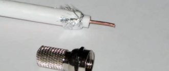
First of all, you should pay attention to the TV cable. It should be intact and without any crimps.
- If this is a multi-story building, then you will only have to check the functionality of one end of the cable (with a plug). For this, a multimeter (tester) is used to measure the resistance between the braid and the central core of the wire. A value of several tens of ohms is considered a normal value. If it is greater than or close to “0”, a break or short circuit has occurred. In this case, it is better to find out whether the neighbors have a signal and, if so, then the problem is in the junction box or in the area from it to the plug.
- If this is a private home, then you can check the resistance of both ends of the TV cable. First you need to unplug all equipment from the outlet. Then disconnect the wire from the antenna and from the TV. And in the same way, use a tester to check the braiding and the central core for short circuits. Here, the serviceability of the cable is indicated by an infinite resistance value. But, if you short-circuit the central core and braid, the multimeter should show a value close to “0”.
When the device detects a malfunction, it is necessary, first, to find the weak point of the cable. This usually occurs in places where there are sharp bends, connected sections, or where the wind sways. If everything is fine with the TV cable, the cause of the problem should be looked for elsewhere.
TV signal level according to GOST
The TV signal level is measured in decibels (dB), taken in relation to the effective voltage (1 µV). The designation looks like this: “dBµV”. In accordance with existing GOST, the value of this parameter should be in the range from 60 to 78 dBµV (these indicators are focused on a package that includes more than twenty programs). The optimal level of a television signal, at which the input signal-to-noise ratio has acceptable values (26 dB), is an indicator of the sensitivity of the television receiver. This parameter is specified in the device passport. Modern TV receivers are designed for a minimum input signal:
- 32 dBmV in the meter range;
- 37 dBmV in the UHF range.
Taking into account the fact that acceptable image quality is observed only at a signal level value that exceeds the receiver sensitivity rating by 20 dB, this value at the input of the receiving equipment should vary in the range of 52-57 dBmV.
In addition to this indicator, the signal characteristics are seriously influenced by such parameters as the ratio of signal to noise levels, as well as the level of intermodulation (nonlinear) distortion. Typically, such complex measurements are not carried out by specialists, but, nevertheless, the quality of the image largely depends on them.
According to existing standards (GOST [2.3]), the value of these parameters should not exceed:
- -72 dB/mW (70 µV) for meter range;
- -69 dB/mW (100 µV) for the UHF range.
The sensitivity of an individual video channel, taking into account the limitations associated with synchronization, directly depends on the minimum signal amplitude at the input of the television receiver, which ensures stable image synchronization. The meaning of these parameters is as follows:
- in the meter range it is acceptable within -75 dB/mW (40 µV);
- in decimeter - should not exceed -72 dB/mW (70 µV).
Benefits of MER
MER (Modulation Error Ratio) is a modulation error that characterizes the deviation of a real symbol from the location of an ideal symbol on a constellation diagram1.
Compared to BER, MER provides more immediate information about the signal. As I already mentioned, MER is similar to the signal-to-noise ratio parameter, although it takes into account more factors that distort the original radio signal. The parameter value is also averaged over time, like all quantities associated with power measurement, but its measurement is carried out for each symbol and, taking into account high symbol rates, accumulation in one second gives a fairly reliable result.
The second advantage of the MER parameter is the ability to measure it with normalized accuracy. Most modern decoder chips, on the basis of which devices are manufactured, allow you to calculate MER in hardware or based on the magnitudes of the amplitudes of the I and Q vectors.
By hardware calculation I mean the ability to obtain the root mean square value of the error vector from one of the demodulator's internal registers. In any case, chip manufacturers claim that this is exactly it, and measurements, in principle, confirm this. And knowing the root-mean-square value of the error vector, calculating MER is not difficult.
Using quadrature vector amplitude values for these purposes is often less suitable because only 7 or 8 bits of QI vector amplitude can be obtained from the chip. As a result, the dynamic range of the calculated MER value is quite low. On the contrary, the width of the error register is often 10 or even 16 bits.
Measurement uncertainty associated with non-ideal tuner and demodulator parameters can be corrected by having a signal source with a calibrated signal-to-noise parameter. The calibration is performed on an input signal with only white noise added, but this method nevertheless gives a very good result.
Therefore, the error of the MER parameter for many devices is a normalized value, unlike BER. The accuracy of BER measurements depends on the quality of the instrument's receiver and demodulator and cannot be corrected. As a result, measuring BER with different devices gives similar values when bad and noticeably different when good (at large MER values).
That is, a better device shows lower (closer to real) BER values. The ability to measure low BER values is a good indicator of the quality of the measuring instrument.
If this is so, the question arises: “Isn’t it enough to measure MER alone to assess the quality of the received signal, since the measurement time is short. The parameter provides comprehensive and accurate information. We can agree with this, but only in one case, when only white Gaussian noise is mixed into the original signal. As practice and test modeling show, when this condition is met, MER coincides with SNR, and therefore, in this case, to determine the values of preBER and postBER, you can use the curves of BER depending on the SNR ratio of the input signal.
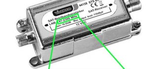
Measuring a TV signal using a multimeter
A multimeter is a universal measuring device that can be used to measure voltage, current, resistance, capacitance, inductance, and also carry out cable testing. Some types of stationary devices of this type are equipped with a frequency measurement unit. I would like to immediately note that it is impossible to measure the level of a TV signal with a conventional multimeter. If the device has a built-in frequency meter, it becomes possible, when setting up a specific channel, to check the correspondence of the specified value and the actual indicator of this parameter when setting up the antenna. Basically, a multimeter is used to measure the resistance of an antenna cable and check its integrity.
DVB-T2
The digital broadcasting standard adopted in Russia can also be transmitted via cable.
The shape of the constellation at first glance may be somewhat surprising: This rotation additionally increases noise immunity, since the receiver knows that the constellation must be rotated by a given angle, which means it can filter what comes without a built-in shift. It can be seen that for this standard the bit error rates are an order of magnitude higher and the errors in the signal before processing no longer exceed the measurement limit, but amount to a very real 8.6 per million. To correct them, an LDPC
, so the parameter is called LBER. Due to increased noise immunity, this standard supports a modulation level of 256QAM, but currently only 64QAM is used in broadcasting.
Measuring TV signal in SCTV
To measure the basic characteristics of a television signal in a cable TV network (cable television network system or SCS cable network system), you will need a signal generator, a spectrum analyzer and a digital oscilloscope.
These measurements include:
- Impulse noise level. It is carried out by the method of accumulating sweeps, from the characteristics of which, using special software, such characteristics of the output signal as the width and amplitude of the pulses, as well as their periodicity, are calculated. Such measurements are carried out in conjunction with recording the level of total interference. The scan should be recorded at intervals of 2-8 seconds;
- Total interference level. Such measurements are performed using a spectrum analyzer by recording spectral analysis data of the interference, and are carried out at intervals of 8-10 seconds. Testing is carried out over eight hours. In this case, the bandwidth of the device is set:
- at intermediate frequency at 30 kHz;
- via video at 10 kHz;
- the detector is switched to peak mode.
Using the appropriate software, the spectral power is adjusted and the ratio of the signal power level and the total interference for a single channel is determined;
- Determination of the frequency response of the path. The determination of these characteristics is based on the method of analyzing the distortions of a test signal of a certain shape, supplied by a pulse generator to the input of the path. To perform such measurements, the following equipment is required:
- Pulse generator used as a source of the tested signal;
- digital high-frequency oscilloscope (with a bandwidth of up to 50 MHz), equipped with an interface for transmitting received information;
- a device for storing the obtained results connected to an oscilloscope.
The resistance at the input and output of the devices used must correspond to the indicator - 75 Ohms.
BER measurement time
Most instruments for measuring the parameters of digitally modulated signals have a lower limit of the measurement range of the BER parameter 1E-8 or 1E-9, less often - 1E-10, 1E-11. It is quite natural that instrument users want to have the limit as low as possible and obtain the measurement result as quickly as possible. Let's do the math: if we use QAM-256 modulation and a symbol rate of 6.9 Mbaud, then the bit rate at the input of the ReedSolomon decoder will be 6.9 * 8 = 55.2 Mbps. If the probability of an error occurring is 1E-8, then to measure this value we need to accumulate 108 bits of the data stream, of which one bit will be erroneous. And we will accumulate them within 108/55.2×106 = 1.8 s. That is, one incorrectly decoded bit will appear, on average, once every two seconds.
The result measured over this period of time will, of course, be highly inaccurate. To reduce the random error, it is necessary to average it over at least 10 measurement periods, that is, 18 seconds. If we want to measure BER with a lower limit of 1E-9, then we will need 10 times longer: 180 seconds or 3 minutes, and to get a reliable result of 1E-11 we must wait five hours! If you use lower order modulation or a lower symbol rate, the measurement time will increase even more
Measuring a TV signal in an optical cable
The main element of fiber optic networks is the fiber located inside the optical cable. To maintain and test such systems, specialized measuring equipment is required. Here are some devices without which it is impossible to perform any measurements on optical lines:
- optical reflectometer (OTDR) – makes it possible to determine not only the level of losses in the system, but also the location of damage to the optical cable;
- optical tester - presented in the form of an independent radiation source and a device for measuring optical signal power;
- optical power meter – records the signal level indicator and displays its numerical value on its screen in Watts or dBm. The main measuring element of the device is a photodetector.
- flaw detector – causes a red glow on damaged sections of the optical cable;
- active fiber identifier – the device is designed for a quick, gentle (non-destructive cable integrity) method for determining the presence of a signal and its direction in an optical fiber. It makes it possible to detect the presence of a signal without turning off the transmitting and receiving equipment, as well as determine its strength and direction.
Let's figure out what characteristics of fiber-optic communications we are talking about when servicing and repairing them. The first indicator that experts pay attention to is the level of attenuation of the optical signal at a certain wavelength (measured in dB). This value characterizes the quality of the fiber optic cable and the level of installation work performed during its installation. The main elements of the system that cause this process to occur are:
- optical fiber (losses are measured in dB per unit distance);
- welding connections;
- connectors;
- connectors;
- dividers, etc.
The next important characteristic for optical communications is back reflection. This value determines the power of the signal reflected to its source and is also expressed in dB. The main reasons for the occurrence of a reflected signal, as a rule, are mechanical damage to the optical cable (cracks), the presence of mechanical connectors, or a cable break at the connection point (free end).
The use of the above devices allows a specialist to achieve the output signal to the required level and ensure reliable operation of the receiving equipment located in the apartment or house. So, if you have problems with the image in SCTV conditions, you should contact the operator who provides these services to you.
Setting up television antennas at home is usually done using receiving and reproducing household equipment located in an apartment or house. The presence of a receiver and a TV in this case is sufficient to determine the signal level and correct it. We are, of course, talking about a primitive coordination of the elements of the chain, which includes an antenna, cable and television receiving equipment. For deeper settings, specialists use professional measuring instruments, which can greatly reduce the time of such work and simplify their implementation. The use of such devices makes it possible to determine the signal level in a matter of minutes and adjust the receiving antenna in accordance with the passport parameters of the receiving household appliance.
What is the problem?
Find out how to fix some common TV signal problems.
Some digital TV channels are missing
If not all channels are working, your TV may be receiving multiple signals and trying to install channels from multiple regions. To solve this problem, you will have to manually configure your digital television tuner.
First, you need to write down the channel numbers for your priority transmitter. These are called multiplex channel numbers.
Once you know the channel numbers, you will need to reinstall each channel manually (see instructions in your TV or digital receiver manual).
A shadow appears on the TV picture
If a shadow of another channel appears in the background of the picture while watching a TV channel, this is often due to poor quality SCART cable.
This happens due to poor cable shielding, and unfortunately, most of the cables that come with set-top boxes are of poor quality. To avoid this situation, purchase a quality SCART cable
(such a cable has a separate foil shield that prevents other signals from being received).
There are bright flashes of white lines or dots on the TV screen
A common cause of this problem is electrical noise, which can cause the picture to be interrupted. Typically this takes less than a minute.
Common causes of these obstructions include a faulty central heating system regulator, water heater thermostat, intermittent switches, breakers or outlets in the building. When electrical noise occurs, turn off central heating or hot water temporarily
and check if the problem has been resolved.
Electrical interference can also be caused by appliances operating in neighboring houses. Industrial garages or maintenance facilities may operate equipment, particularly arc welders, that generate high levels of electrical noise.
This problem occurs more often with antennas that are installed in the attic than with those that are located on the roof. To avoid electrical interference, use double-shielded coaxial cable
to connect the antenna for a set-top box or TV, but be careful not to run the wire too close to the electrical wires in your home.
TV picture keeps freezing
Often this problem is caused by pulsed noise, which can be generated by vehicle ignition systems,
located near your home.
To avoid these obstacles, try raising your TV antenna higher and be sure to use double shielded coaxial cable
to connect an antenna for a set-top box or TV.
Learn more about cable types and their impact on TV picture quality.
Horizontal stripes or patterns appear on the TV screen
This type of problem is called TETRA obstacles, which are created by the frequencies of walkie-talkies,
which are commonly used by government agencies, military organizations, emergency services and transportation services.
If you have problems with TETRA obstacles, we recommend purchasing a high-pass filter or a TETRA UHF notch filter. For more information, contact your local electrical retail store.
Checking the TV signal without a TV
The technique for measuring the level of a television signal without using household appliances consists of connecting the appropriate equipment to the circuit between the antenna and the receiver, or directly to the antenna cable. Using this method, the measuring device records the level of the input signal, and the specialist determines its parameters. In accordance with the results obtained, the built-in receiving unit of the TV or a separately connected receiver is configured. In this case, the specialist can only correctly orient the receiving antenna and coordinate its parameters with the passport characteristics of the receiving equipment. Usually the antenna is directed in such a way as to obtain the maximum level of the TV signal.
Modern devices for tuning standard and satellite antennas are now available in a very wide range. These include:
- TV signal level meters with dial or digital indication;
- devices with a built-in compass that determines the position of the satellite;
- devices with their own software and the ability to enter additional settings;
- spectrum analyzers used for finer and more precise tuning of receiving equipment;
- universal analyzers operating in TV receiver mode with support for various image formats.
The choice of the type of measuring equipment directly depends on the type of antenna and the tasks assigned to the specialist.
Where to point the antenna to receive a digital signal
The most accurate information about operating frequencies and the location of television transmitters is on the website of the Russian Television and Radio Broadcasting Network and on our page.
To get the information you need, go to the map page, then check the “Digital Broadcasting” box, as well as o. Next, look for your locality. Markers of the location of the towers, as well as broadcast frequencies by zone, will appear on the map in front of you.
Example coverage map: tower locations and frequency ranges.
TV signal level according to GOST
The TV signal level is measured in decibels (dB), taken in relation to the effective voltage (1 µV). The designation looks like this: “dBµV”. In accordance with existing GOST, the value of this parameter should be in the range from 60 to 78 dBµV (these indicators are focused on a package that includes more than twenty programs). The optimal level of a television signal, at which the input signal-to-noise ratio has acceptable values (26 dB), is an indicator of the sensitivity of the television receiver. This parameter is specified in the device passport. Modern TV receivers are designed for a minimum input signal:
- 32 dBmV in the meter range;
- 37 dBmV in the UHF range.
Taking into account the fact that acceptable image quality is observed only at a signal level value that exceeds the receiver sensitivity rating by 20 dB, this value at the input of the receiving equipment should vary in the range of 52-57 dBmV.
In addition to this indicator, the signal characteristics are seriously influenced by such parameters as the ratio of signal to noise levels, as well as the level of intermodulation (nonlinear) distortion. Typically, such complex measurements are not carried out by specialists, but, nevertheless, the quality of the image largely depends on them.
According to existing standards (GOST [2.3]), the value of these parameters should not exceed:
- -72 dB/mW (70 µV) for meter range;
- -69 dB/mW (100 µV) for the UHF range.
The sensitivity of an individual video channel, taking into account the limitations associated with synchronization, directly depends on the minimum signal amplitude at the input of the television receiver, which ensures stable image synchronization. The meaning of these parameters is as follows:
- in the meter range it is acceptable within -75 dB/mW (40 µV);
- in decimeter - should not exceed -72 dB/mW (70 µV).
Five main parameters
First, let's look at the set of measured parameters of digital channels available to owners of modern devices. Typically, these devices allow you to measure five parameters.
The first of them is the signal level in the channel. Without a doubt, this is one of the most important parameters characterizing the quality of reception. Despite the fact that this is the most understandable parameter for specialists and can be measured with sufficient accuracy even with instruments designed for analog signals, when analyzing measurement results there are sometimes misinterpretations and misunderstandings.
The next parameter is MER (Modulation Error Ratio), or Modulation Error Ratio. At its core, MER is close to the SNR (signal to noise) parameter. Some countries use EVM (Error Vector Magnitude) instead of MER, but they are essentially the same thing expressed in different units.
The third parameter is BER (Bit Error Ratio), or Bit Error Ratio. It characterizes the frequency of occurrence of erroneously recovered bits in the demodulated data stream and for the DVB-C standard it is measured at two points: before and after the ReedSolomon decoder. Therefore, these are actually two parameters that are often given the names preBER and postBER. The postBER parameter is a value that is sometimes presented to the user as the value of the counter of erroneous packets for the observation interval.
The last parameter is a constellation diagram, which is a graph of the location of symbols on the amplitude-phase plane, formed with accumulation over a certain time. As a rule, the diagram is considered as a kind of qualitative, rather than quantitative, parameter that allows one to evaluate the nature of the distortion of the input radio signal.
Now we can begin a more detailed analysis of each of the parameters for their importance in assessing the quality of the received digital signal.
Measuring a TV signal using a multimeter
A multimeter is a universal measuring device that can be used to measure voltage, current, resistance, capacitance, inductance, and also carry out cable testing. Some types of stationary devices of this type are equipped with a frequency measurement unit. I would like to immediately note that it is impossible to measure the level of a TV signal with a conventional multimeter. If the device has a built-in frequency meter, it becomes possible, when setting up a specific channel, to check the correspondence of the specified value and the actual indicator of this parameter when setting up the antenna. Basically, a multimeter is used to measure the resistance of an antenna cable and check its integrity.
How to check your satellite dish receiver
Before you begin your next attempt to test the antenna, it is best to try the previous steps again. Perhaps there was a mistake made somewhere. If nothing helps, you can check the receiver for serviceability.
- First, you should go into manual settings and write down the parameters for the satellite of this provider.
- Then, take the device and connect it to another satellite TV.
- After that, select manual search in the menu, where to find the desired satellite and set the already recorded parameters.
- If both scales are colored and have a numerical value, then the receiver is working properly, otherwise it will have to be sent in for repair.
In any case, you should not immediately rush out and buy a faulty element or call a repairman. It is better to try to go through each point of checking the television antenna 2-3 times. And only then can we draw any conclusions.
Measuring TV signal in SCTV
To measure the basic characteristics of a television signal in a cable TV network (cable television network system or SCS cable network system), you will need a signal generator, a spectrum analyzer and a digital oscilloscope.
These measurements include:
- Impulse noise level. It is carried out by the method of accumulating sweeps, from the characteristics of which, using special software, such characteristics of the output signal as the width and amplitude of the pulses, as well as their periodicity, are calculated. Such measurements are carried out in conjunction with recording the level of total interference. The scan should be recorded at intervals of 2-8 seconds;
- Total interference level. Such measurements are performed using a spectrum analyzer by recording spectral analysis data of the interference, and are carried out at intervals of 8-10 seconds. Testing is carried out over eight hours. In this case, the bandwidth of the device is set:
- at intermediate frequency at 30 kHz;
- via video at 10 kHz;
- the detector is switched to peak mode.
Using the appropriate software, the spectral power is adjusted and the ratio of the signal power level and the total interference for a single channel is determined;
- Determination of the frequency response of the path. The determination of these characteristics is based on the method of analyzing the distortions of a test signal of a certain shape, supplied by a pulse generator to the input of the path. To perform such measurements, the following equipment is required:
- Pulse generator used as a source of the tested signal;
- digital high-frequency oscilloscope (with a bandwidth of up to 50 MHz), equipped with an interface for transmitting received information;
- a device for storing the obtained results connected to an oscilloscope.
The resistance at the input and output of the devices used must correspond to the indicator - 75 Ohms.
DVB-C
This standard was originally created for transmission via cable (C - Cable) - a medium much more stable than air, therefore it allows the use of a higher degree of modulation than DVB-T, and therefore transmits a larger amount of information without using complex coding.
Here we see the constellation 256QAM. There are more squares, their size has become smaller. The probability of error has increased, which means that a more reliable medium (or more complex coding, as in DVB-T2) is needed to transmit such a signal. Such a signal can “scatter” where analog and DVB-T/T2 work, but it also has a margin of noise immunity and error correction algorithms.
Due to the higher probability of error, the MER parameter for 256-QAM is normalized to 32 dB.
The counter of erroneous bits has risen another order of magnitude and now calculates one erroneous bit per billion, but even if there are hundreds of millions of them (PRE-BER ~E-07-8), the Reed-Solomon decoder used in this standard will eliminate all errors.
Signal types
Signals based on the physical environment of the information carrier are divided into electrical, optical, acoustic and electromagnetic.
According to the setting method, the signal can be regular or irregular. A regular signal is represented as a deterministic function of time. An irregular signal in radio engineering is represented by a chaotic function of time and is analyzed using a probabilistic approach.
Signals, depending on the function that describes their parameters, can be analog or discrete. A discrete signal that has been quantized is called a digital signal.
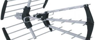
Types of antennas for amplifying digital TV
If you are faced with a problem with TV signal quality, you will need basic information on the types of antenna equipment to make an informed choice.
The following types of antennas are used in subscriber equipment for television reception:
- Telescopic
- Patch antennas
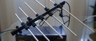
- Wave channel
- Zigzag
Educational program on the main types of ready-made television antennas for terrestrial television
A telescopic antenna, also known as a rod antenna, has a low gain. Easy to manufacture and therefore cheap. Used at distances up to 5 kilometers from the repeater. Polarization type: circular. That is, the antenna “sees” all radio waves. Usually indoor. To increase signal stability, they are sometimes equipped with a built-in amplifier.
Patch antenna. It consists of several, usually rectangular, elements, which are protected by a plastic case. Polarization - vertical and horizontal. That is, the antenna can be placed in the position in which television and radio waves propagate from a repeater in your region. The main advantage over other options is the high gain and at the same time the ability to receive a reflected signal. There are products with a built-in amplifier.
Wave channel or Yagi. The most common type of television antenna. It looks like several elements (directors, reflectors and vibrators) located on a traverse. A subtype of wave channel includes products with periodically repeating element lengths—log-periodic antennas. Usually it is an outdoor antenna. However, there are also indoor options on a stand. The most powerful ones are equipped with side reflectors (reflectors). Often equipped with built-in amplifiers and filters.
The rating of the best antennas for digital television is presented here.