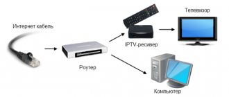
Unlike terrestrial cable television, it is not received by an antenna from a television repeater, but is supplied by cable directly to the apartment. This method allows you to minimize signal loss and improve picture quality. Cable TV gives the operator the opportunity to independently regulate the number of channels, their format and encoding method. Cable TV provides subscribers with dozens and even hundreds of channels, both in analog and digital quality. Determining that you have cable TV is quite simple:
if your TV receives more than 20 channels, you are watching cable TV.
Typically, cable operators, to minimize financial losses, calculate the signal level as one TV per apartment. As a result, when wiring cables to several TVs, you have to resort to the help of an amplifier.
The difference between cable amplifiers and terrestrial amplifiers
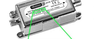
Why do you need special amplifiers for cable television? The fact is that cable operators use the entire frequency range from 47-862 MHz, and on the air the range from 318 to 470 MHz is not used. Respectively
over-the-air amplifiers do not amplify part of the cable range or cut it out altogether
,
which will accordingly lead to the loss of some channels.
Cable amplifiers, like terrestrial amplifiers, are mainline
and are used by operators for wiring to the entrance or even the entire house and
household appliances
, which are installed already in the apartment to compensate for losses in wiring to TVs in the apartment itself.
If there is a lack of signal in the subscriber's area, the amplifier is selected based on the difference in level between the signal entering the apartment and the signal directly from the TV.
The most popular is the household amplifier of the Spanish company Alcad AI-131
. This is an inexpensive cable amplifier with a maximum gain of 24 dB. This gain is usually quite enough to compensate for the wiring of 3-4 TVs. The amplifier has adjustment of the frequency response slope and the gain level itself. Adjusting the slope of the frequency response, simply put, is the frequency at which there will be a peak of maximum gain, other frequencies, like the slope of a mountain, will have a lower gain.
Wiring losses can also be compensated for by an amplifier with multiple outputs. In this case, the amplifier itself is a divider and you avoid signal loss during division. For example, amplifier Televes 55324 1
has 2 outputs and a gain of 20 DB, and
Televes 5531
has 6 outputs and a gain of 16 DB.
However, it happens that such amplification is not enough. There are several reasons for this:
- Long cable length;
- Old or poor quality cable;
- Serial wiring;
- Low input signal level;
For these cases, it is necessary to use more powerful amplifiers, for example, the Terra HA123
(28dB), amplifier
Terra HA126
(34dB). These powerful amplifiers, in terms of their characteristics, although they belong to the main line, are often used instead of household amplifiers when a household amplifier is not enough. Terra amplifiers also have frequency response and gain adjustments, which will allow you to achieve the optimal output signal.
Another difference between cable amplifiers and terrestrial amplifiers is that they work with the return channel range of 5-30 MHz, which is used by Internet providers to organize Internet access via television coaxial cable. Currently, this technology is practically not used in our country.
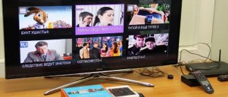
Home cable amplifier Seebest 8830H4
Using cable television on 2 TVs, it became necessary to connect an additional TV + PC Tuner to it. I don’t watch TV at all, but my family asked me to put it in the kitchen and on the computer. I tried to divide the signal with a 4-channel splitter, but the signal power in the cable turned out to be insufficient - noticeable noise appears in the image of analog channels. There is nothing to do - you need to install a cable signal amplifier. A little theory in your own words
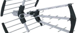
TV range amplifiers for household use are divided into two main types: 1. Antenna - installed mainly next to the antenna or on it itself and serves mainly to match and compensate for signal losses in the reduction cable. Typically, an antenna amplifier is enough to operate several TVs, provided there is a compact cable layout. Some features - low noise figure - low gain (so as not to overload the output) - wide operating temperature range - power is usually supplied by the injector through the reduction cable itself along with the signal. 2. Cable (linear, house) - usually installed in a break in the house wiring cable and serves mainly to raise the signal level and correct the frequency response (Amplitude-Frequency Characteristic). This is necessary for long house wiring and for efficient signal division. A powerful cable amplifier is quite enough to wire the entire entrance of a multi-story building. Some features: - high adjustable gain (20-35dB) - high output power and overload capacity - sometimes the presence of adjustable correction of the frequency response slope - sometimes the presence of an indication of the output signal power - often have a built-in splitter (divider) at the output - mains power Many people make the mistake of they confuse the types of amplifiers and, worse, choose them incorrectly. Yes, in some cases, a cable amplifier can be used instead of an antenna, as well as an antenna instead of a cable, but such a replacement is not always successful and optimal.
An important note: any amplifier must be installed as close to the signal source as possible. This allows you to reduce the noise value of the amplifier itself in the received signal. The most correct place to install a cable amplifier is at the cable entry into the apartment (house). Further, depending on the cabling topology: - immediately divide the signal with a splitter and run separate cables to each consumer. - run with a single cable, but place a signal coupler near each consumer. - combine the method of division and branching.
Previously, for similar purposes, I installed LOCUS LHA-120 (LHA-121) amplifiers, which still work quite well to this day, but for some reason they stopped producing and selling them. Finding a high-quality amplifier is not a problem (for example Terra), but it is much more expensive. I had to find an analogue for reasonable money. The choice fell on the Chinese home amplifier Seebest 8830H4. Reviews of the work are positive, the characteristics are pleasing, the appearance is quite decent. Among the visually noticeable disadvantages are the alien power plug and the absence of an output power indicator. The plug is easy to change, and you can do without an output power indicator.
Declared main technical characteristics
Frequency range 45~860 MHz Noise figure ≤5 dB Signal amplification 30±2 dB Gain adjustment 0~10 dB Frequency response flatness ±0.75 dB Frequency response slope adjustment 3-18 dB Maximum output signal level 109 dBμV
The parcel arrived a month after ordering.
For packaging lovers
Inside was another box with a picture of a happy Chinese man
For box lovers
The kit includes 5 nuts for connecting cables to the amplifier. The real ambush is the connection sockets. Standard cable nuts are not screwed onto them, but only screwed in. Standard inch 3/8″ connectors have a thread pitch of 0.7938 mm and a diameter of 9.525 mm, and Chinese metric connectors M10x0.75 have a diameter of 10 mm and a thread pitch of 0.75 mm. Those. Now you have to unscrew the previously installed nuts and replace them with complete ones. Not a very convenient solution... Unfortunately, the power plug is not compatible with our sockets - I will redo it.
According to tradition, the amplifier was disassembled. The build quality of the amplifier is a solid 4, but the installation let us down. The flux has not been washed, the soldering is of poor quality in places, there are solder “snot”. The socket lamella is not soldered
“Snot” of solder on the matching trance
Here I removed the “snot”
I removed the excess solder, the board about class=”aligncenter” width=”800″ height=”378″|fcw3qayjh5a| src=”https://img.mysku-st.ru/uploads/images/02/80/11/2015/02/08/4c87d4.jpg” class=”aligncenter” width=”800″ height=”600″ [/img]
I immediately changed the power plug along with the wire, the quality of which did not inspire confidence. Was: Now:
It remains to solve the problem with the Chinese connectors. It is very inconvenient to use the supplied nuts; redoing the connection of existing cables is not an option, because If the amplifier is replaced, everything will have to be redone again.
As a result, it was decided to replace the amplifier connectors themselves with standard F-BJ ones
The amplifier was disassembled again, the standard connectors were carefully soldered out
Resoldering the connectors turned out to be not as simple as I expected. I had to shorten the board by 2mm on each side, because... the new connectors turned out to be not so flat - the hexagon got in the way Ready-made
Now the standard nuts turn normally
Real amplifier circuit with operating modes.
The power supply is assembled on the basis of a conventional low-frequency transformer, which undoubtedly pleased us - there is less internal interference and interference, higher reliability. The power source turned out to be unstabilized - this is of course a minus, but not very critical. But the last cascade is assembled according to the scheme of a push-pull symmetrical cascode, which has a large overload capacity and small even harmonics.
The amplifier is assembled on the basis of low-noise bipolar microwave transistors 2SC3356 (or analogues) pdf.datasheetcatalog.com/datasheet/nec/2SC3356.pdf Description of the main components: BG1 - pre-amplifier Left trimmer - adjustable attenuator Right trimmer, L1, L2, T1 - tilt control Frequency response (does not work) T5 - balun transformer BG2-BG5 - push-pull symmetrical cascode T6 - balun-matching transformer T2-T4 - splitter for 4 outputs All outputs are permanently blocked to the housing. Power consumption from the network is 2.4 W PF = 0.90 Heating of the case is insignificant.
Unfortunately, I don’t have high-frequency measuring equipment for testing, so I tested it using a broadband scanner based on DAB FM DVB-T RTL2832U+R820T, additionally using 10dB and 20dB attenuators, 75 Ohm loads and adapters.
These are, of course, not measuring instruments, but they are quite suitable for approximate assessment and comparison of signal levels at different frequencies.
I will briefly tell you the measurement methodology Initial data - cable network Dom.ru TV Broadcasting method - analog + digital DVB-C including HD 111 MHz - 295 MHz and 455 MHz - 855 MHz analog broadcasting 306 MHz - 450 MHz digital broadcasting Frequencies at the beginning, middle and end of the range were selected for testing : 111.15 MHz, 295.20 MHz, 455.20 MHz, 855.20 MHz The SDRSharp program, widely known in narrow circles, was used. The scanner gain was adjusted to avoid overloading. The gain at a specific frequency was measured by comparing the signal level without an amplifier and from the output of the amplifier through an attenuator - 20dB so that the signal level is approximately the same order. In this case, an absolute change in the signal levels of the selected channels introduces almost no additional measurement error.
The test was carried out on the main video frequency, where frame and horizontal scans are broadcast, because The signal does not jump very much depending on the image.
Checking is impossible on digital channels - the signal spectrum is evenly distributed over the entire frequency channel in the form of noise
Test results: - The gain is really about 30 dB - The attenuator works quite correctly in the entire tested frequency range, adjusting the attenuation by 0-10 dB - Adjusting the frequency response slope does not work normally, the Chinese clearly miscalculated here. Rotating the frequency response tilt control practically does not work over the entire frequency range. Looking at the diagram of the tilt regulator, it is clear that in its original form it cannot even theoretically work normally. In the future I will try to remake it, but now I don’t have the strength - I spent a long time tinkering with the amplifier and writing a review.
The output divider by 4 is also not ideal - the isolation between outputs 1-2 and 3-4 is weak, there is mutual influence of the output signal when connecting loads. More complex measurements (noise figure, reflection coefficient, overload capacity, isolation coefficient between channels) were not carried out due to the lack of technical capabilities.
After installing the amplifier, analog channels show normally without noticeable noise. Digital channels are shown as before without problems. The signal level at the top of the frequency range remained blocked, because adjusting the frequency response slope in the amplifier does not work, but due to a significant overall increase in the signal level, this does not affect the image
Conclusion: The amplifier is working, but with many unpleasant shortcomings - I cannot recommend it, sorry.
Correct installation of the amplifier
To obtain maximum effect, the amplifier must be installed immediately at the entrance to the apartment, before wiring begins. This will help maintain sufficient signal-to-noise ratio at maximum gain. The most effective wiring will be if you combine all the cables into one divider installed immediately after the amplifier. If this is not possible when wiring in series, use taps rather than dividers.
Use a ground isolator to protect the amplifier. Do not use old or thin cable (less than 7mm). Over time, the cable loses its properties, and losses increase significantly. A thin cable has a small cross-section of the central core, which increases signal loss. Do not block the amplifier's ventilation openings with foreign objects, e.g. newspapers, curtains. When installing, mount the amplifier in a position that will allow minimal bending of the television cable. There must be at least 10 cm of free space for ventilation at the top, front and bottom of the installed amplifier.