Pin numbering
The pins are numbered on the board as “digital” D* pins and analog A* pins. We will refer to digital pins simply by their number, i.e. D3 is just 3 . With analog pins it’s a little more complicated:
- You can contact us with the letter A ( A3 , A5 )
- You can use a number in order after the digital ones, for example, for Nano the last digital one is D13 , the next “analog” A0 has number 14 , and for example A5 has number 19 , by which it can also be accessed, which allows you to control all pins using cycles
Optical cable parameters for a high-quality connection
To connect an optical cable to the device while maintaining high sound performance, you need to follow the following rules:
- The length of the wire should not exceed 10 meters. The best option is 5 meters. In this case, the quality of signal transmission will remain unchanged. Also, some manufacturers produce thirty-meter cables that transmit the signal without interruption. But the quality will depend on the receiving device.
- The thicker the cable, the longer it will last.
- The highest quality options are additionally equipped with a shell made of nylon fabric.
- It is important to pay attention to the type of core. Suitable options are silica or glass. They significantly exceed plastic ones in quality.
- Bandwidth must be high. A good cable has between 9 and 11 MHz. This indicator should be chosen if a multi-channel sound system with a significant sampling frequency is installed at home.
History of the system
Until recently, fiber optic cable was not perceived as a tool for high-quality sound transmission. It is known that fast data transmission is possible only with light. Optical technology was first used in the photophone developed by Alexander Bell.
Optical telephone communication proved the possibility of transmitting a signal through the air, but the inventor’s idea itself did not take root. The physicist's achievements began to be used for communication between ships, but nothing more.
The widespread use of fiber optic technologies began only in the mid-20th century, and a major breakthrough that brought digital audio out to the masses occurred in 1980 with the invention of fiberglass wire, which was capable of transmitting a light signal.
Despite the fact that the optical input celebrated its 40th anniversary, it is still considered the best in terms of analog sound transmission quality, which cannot be matched by the “tulip” HDMI cable, which appeared much later.
Typical fiber optic cable design
Fiber optic cable design How to connect a television cable
Optical fiber can be made from:
- Polymer;
- Quartz glass.
Polymer fiber is, as a rule, more resistant to mechanical stress and cheaper. However, over time it may lose transparency, which negatively affects the durability of the product.
Glass light guides have better optical characteristics, but are more expensive and fragile.
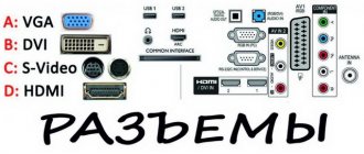
Application areas of various connectors
When a user looks at a computer, TV, or other device, he must understand what cable is used for. It is also worth understanding what types of audio cables there are, for what purposes they are most often used, and much more.
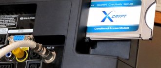
SPDIF out
In fact, this connector is one big name of a type, which is then divided into many others. This type is the most common, but also the oldest. That is why it can only be found in:
- Home cinemas;
- Audio players;
- Car radios;
- Audio players.
This connection goes through the connector that is indicated on the set-top box itself. The connector most often looks like a familiar “tulip”. It is designed for either 75 ohms or 50 ohms. You can also use any other cable that has the same resistance, this option is possible.
Note! SPDIF out is the name of one type. This connector is further divided by wire into coaxial, optical and others.
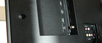
Digital audio out
This is an optical cable that usually consists of one shell and a core. It is adopted as a standard for TVs such as LG, Samsung and many more. It is required for:
- Conversion from a light signal to an electrical one;
- Its further retransmission, and it passes without distortion;
- Receiving a signal from an incoming device;
- Feedback signal to the device.
Digital audio out works on the principle of a standard audio conductor, but the presence of optical connectors allows you to transmit a signal from the TV to other gadgets using special acoustics. At the same time, the user receives perfect sound. This is partly due to the fact that there is no influence on the fields, a special connection is implemented between devices, and electromagnetic radiation is not generated during transmission.
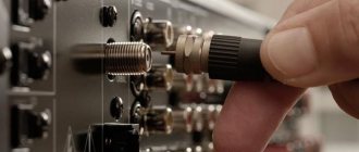
Coaxial connector
Coaxial cable and connector for it are the rarest type. This is because it involves the use of electricity to transmit a signal. It is a round connector, and you can very rarely find it on any devices. This is due to the fact that optical connectors are much more common than coaxial ones. This was exactly the case in 2021.
You can find it on TVs, AV receivers and amplifiers. If we look at televisions, but they can rarely be found anywhere. Most often, it is these connections that are almost impossible to find.
HDMI
HDMI cables are very common on computers, not TVs. Most often, Blu-ray players, consoles, or channels for satellite or cable are connected, and if the TV supports 4K, then you can easily display this image through this connector.
It has an excellent protocol, which sets it apart from other similar cables. Yes, if coaxial and optical cables support both high resolution and high-quality picture, then they will not be able to withstand the current protocol as required. This is what HDMI connection cables do so well. It is also installed by many developers of popular and even top-end computers and televisions. They broadcast communications immediately, without delays, and there are no connection problems. Only if the number of wires.
RCA
This type of connector is most often called a tulip connector. This is primarily due to the fact that it has such a shape. RCA is often used in audio technology, and the standard is called composite. The cables are similar to standard ones, but they have a compact version.
The wire has 3 connectors. The first is needed in order to transmit a two-channel signal, another one is needed for a mono signal, the final signal is simply needed for broadcasting. It may be noted that this wire can be called a component for the rest. It is often crimped, which makes it even more convenient. Everyone will need this connection.
Hi-Fi
Another interesting cable, which is most often an antenna or directly for home theater. Hi-Fi is more often found in older versions of the device. It's not as popular because compression cables aren't seen that often at the moment. The main thing is that such a connection is preserved afterwards, since it is convenient to write music with it.
Thus, each connector and channel had its own connection. It is important to know all the intricacies of the wires so as not to get into trouble in the future when connecting.
4.5/5 — (21 votes)
Pin operation modes
A digital pin can be in two states, input and output . In input mode, the pin can read voltage from 0 to the MK supply voltage, and in output mode it can output the same voltage. The operating mode is selected using the pinMode(pin, mode) function, where pin is the pin number, and mode is the mode:
- mode – operating mode INPUT – input
- OUTPUT – output
- INPUT_PULLUP – input pulled up to power
If everything is clear with the input/output, then let’s figure out the tightening. In input mode, the microcontroller pin is not connected anywhere and picks up all sorts of interference from the air, getting an almost random value. To set the pin to the “default state”, use a pull-up resistor to ground or power. The INPUT_PULLUP mode enables the microcontroller's built-in pin pull-up to power supply . I talked about this in more detail, with diagrams and examples, at the beginning of this video lesson.
By default, all pins are configured as inputs (INPUT)
Using the information from the previous paragraph and the lesson about cycles, you can change the operating mode for example for all pins D2 to A5 :
for (byte i = 2; i <= 19; i++) { // from 2 to 19 (D2-D13, A0-A5) pinMode(i, OUTPUT); // make exits }
Reading a digital signal
A digital pin can “measure” voltage, but it can only report its absence (low level signal, LOW) or presence (high level signal, HIGH), and the absence of voltage is considered to be the range from 0 to ~ 2.1V . Accordingly, from ~2.1V to VCC (up to 5V) the microcontroller considers the presence of a high-level signal. Thus, the microcontroller can easily work with logical devices that send it a high signal with a voltage of 3.3V; it will accept such a signal as HIGH .
You cannot apply a voltage higher than the microcontroller supply voltage to the digital pin (or any other pin either).
To read the signal level on a pin, use the digitalRead(pin) function, where pin is the pin number according to the signature on the board. These are pins labeled D , as well as pins A0-A5 for Arduino Nano/Uno/Pro Mini. This function returns 0 if the signal is low, and 1 if it is high. Simple example:
void setup() { Serial.begin(9600); } void loop() { Serial.println(digitalRead(5)); }
This code will output a signal on pin D5 to the port. If you connect it with a wire to VCC, we get 1, if to GND, we get 0.