Connecting audio/video equipment directly to your TV
TV antenna
An antenna for receiving over-the-air broadcasts is the easiest way to connect to a TV.
Your antenna cable carries broadcast analog or digital signals that it receives from your rooftop antenna or through your cable provider. In most cases, all you need to do is connect this cable to your TV's UHF/VHF input (usually labeled ANT or ANT/CABLE), and this applies to both video and audio.
Satellite television
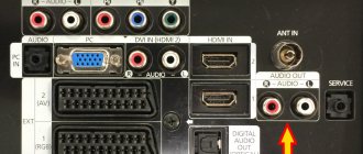
Connectors of a modern LED TV
Modern audio-video equipment is equipped with various kinds of connectors. This is done for the convenience of compatibility of equipment from different years of production and from different manufacturers. The connectors are used to transmit various types of signals - video or audio. The main difference between connectors on modern TVs is their purpose: what signal we transmit, configuration, transmission speed, compatibility with various electronic devices.
Let's look at what connectors exist for connecting equipment. Audio connectors - RCA connector (tulip)
Mini jack 3.5 (mainly used for connecting headphones)
S/PDIF or S/P-DIF (Sony/Philips Digital Interface) is a standard audio transmission format. It is usually found on digital devices that process and transmit sound. This allows you to transfer audio sound from one device to another without converting it to analog, which can degrade the sound quality.
Video Connectors: Video-RCA Composite (mostly yellow)
Component YPbPr YPbPr, component video, is a three-dimensional color space. It is used to encode an analog color video signal and transmit it over three channels at once. The name “component” is explained by the fact that the components of the video signal are transmitted over several channels
SCART (SCART) connector Used to connect various multimedia devices of the European standard. Analog and digital commands can be transmitted through this connector. The multi-pole plug combines all the necessary signals.
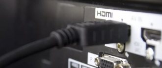
HDMI (High Definition Multimedia Interface) Connector This interface is a standard for creating audio and video connections between high-definition electronic devices. HDMI supports two-way digital communication between a video source and a video display using a single cable. The simple connection scheme has made HDMI popular for home theaters and other multimedia devices.
S-Video (Separate Video) Is a video transmission in which the luminance signal and chrominance signal are transmitted separately to achieve superior image clarity.
VGA and DVI connectors
Other connectors used in video equipment: Antenna connector (RF)
F- connector (used to connect a satellite dish)
RJ-45 LAN / Ethernet (used to connect to the Internet)
CI slot = CI alebo CI+ (Common Interface) This connector is used to connect the CAM module (Conditional-access module). You can find it on the side or back of the TV. For a satellite receiver, it is most often located on the front panel.
Author: silver from 01/24/2019, views: 627
Source: migsat.ru
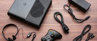
Sending audio from your TV to your receiver via HDMI
If you use your TV's built-in tuner to watch HD over-the-air broadcasts and you want to enjoy surround sound from those TV shows, there are several ways to do so.
Almost any modern TV will have an optical digital audio output, so you can send the audio signal back to your receiver over an optical cable. (All new TVs typically no longer have an analog audio output, so a digital connection may be your only option.)
Almost all modern TVs and home theater receivers have at least one HDMI input with Audio Return Channel (ARC) functionality.
If you have a TV and a receiver with this feature, you can send audio from your TV back to the receiver using the same HDMI cable that you use to connect the receiver to your TV. This way, you won't need to create a separate audio connection over an optical cable.
If you're not sure whether your device supports ARC, look for the HDMI input labeled "ARC." You don't need a special HDMI cable for this feature to work - any modern quality cable will do the job. Almost all receivers released after 2010 are equipped with the HDMI ARC interface.
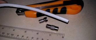
How to connect the cable
Connecting acoustics to a TV or other equipment via an optical input should not cause difficulties, but there are a number of issues.
Direct connection via connector
The optical communication port is usually covered with a protective cover that prevents dust from entering. It is enough to lightly press the connector on it, and it will open, making the connection. If the signal is not received, it is worth checking the active audio outputs in the settings, as well as the volume level on the connected devices.
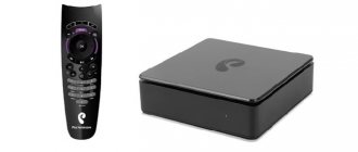
Connection via set-top box or converter
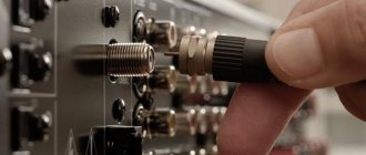
Coaxial input
Often, a home theater system was assembled in stages, over different years. There are situations when the receiver does not have an optical input.
In this case, in order to achieve ideal sound using fiber optics, you will need to purchase a special set-top box that allows you to connect via optical fiber.
This set-top box has two connectors for optical and coaxial cable. To connect the system:
- insert optical fiber into the output of a TV or other device;
- connect the cable to the connector on the set-top box;
- Connect an audio system via the coaxial input.
This is the simplest option for converting an audio signal.
The use of an active converter that converts a 5.1 digital signal into analog is considered advanced. This adapter provides a number of additional options, for example, connecting other types of cables, headphones, or a game console.
Optical cable parameters for a high-quality connection
It is optimal if the core is glass or silica.
To connect the sound source and the speaker system, while maintaining high sound quality, the following rules must be observed:
- Some experts say that the use of an optical cable longer than 10 meters is not allowed, believing that the distance between devices should not exceed 5 meters. In practice, optics have a long range without loss of signal strength. Some manufacturers produce cords up to 30 meters long;
- The cable length must be generous. Due to its thickness, it cannot be bent.
- The thicker the cable, the better the insulation and performance. Thick wire will last longer;
- premium segment wires are equipped with nylon winding, which has a positive effect on the quality of signal transmission and protects against mechanical damage;
- The type of core is important. It is optimal if it is glass or silica. Such solutions are much more effective than plastic ones, with better signal conductivity;
- The bandwidth of a good optical fiber is from 9 to 11 MHz. Only this indicator will meet the needs of multi-channel acoustics with a high sampling rate.
The presence of an optical input indicates the possibility of creating a speaker system with crystal clear sound. At the same time, organization will require the purchase of cords and sometimes additional equipment. When purchasing consumables and organizing connections, you should follow a number of rules, without which you will not be able to achieve HI-end sound.
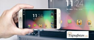
Connecting Smart TV to the Internet
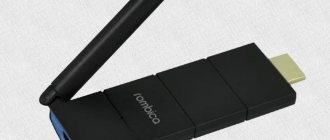
If you have an internet-ready TV, you'll need to connect it to your existing home network to access online content. Most of these TVs have Wi-Fi®, but some still require a wired Ethernet connection.
If you're connecting over a wireless network, you'll likely be prompted to enter information such as your network name and any security passwords you use to protect your network.
If you have a DLNA-compatible TV, you'll need to go through the same steps to access music, photos, and videos stored on your computer. You may also need to configure security settings on your computer.
Connecting the TV to a signal source
Below are the connections you are sure to find on your TV.
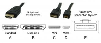
HDMI
HDMI can carry high-definition video and high-definition multi-channel audio.
This is generally the best option for high-definition video because it can carry full 1080p signals, and it's your only option if you're connecting a 4K video source to a 4K TV or a 3D video source to a 3D TV. For a detailed overview of HDMI, see our HDMI cables buying guide.
Signal type: digital
Maximum Resolution: 4K
Component video
Component video also has high resolution, making it a good alternative when HDMI is not available. Component connection provides the most accurate picture of any* analog video transmission method. Instead of three full-size RCA jacks, many new TVs use a mini jack, which requires a special adapter (usually included with the TV).
Signal type: analog
Maximum resolution: 1080p (however, most video sources over a component connection will only deliver 1080i video)
* among household interfaces
Composite video
This is the most versatile video connector. It's still found on most modern TVs, but instead of the standard full-size RCA jack, many newer TVs use a composite minijack connector, which requires a special adapter (usually supplied with the TV). Picture quality is a step up from RF connection (described below), but not as good as component video.
Signal type: analog
Maximum resolution: 480i
| Coaxial or RF video |
Probably the most common way to transmit images to a TV is through RF coaxial connections.
There's a reason why RF inputs on TVs are usually labeled "Antenna" or "Cable" - those are the signals they were designed for. RF connections are generally limited to transmitting signals to your TV from outside the home: TV broadcast, cable TV jack or satellite dish.
Signal type: analog
Maximum resolution: 350i
Connecting the AV receiver to your TV
How to Get the Best Image Quality from Any Source
Modern TVs and video sources can provide truly impressive images. TV manufacturers typically equip their devices with several types of different audio/video inputs (although these options have narrowed over the past few years).
But one wrong connection can seriously compromise the video quality. High-definition images are a quantum leap in quality compared to standard definition, while 4K/HDR images provide even more realistic contrast, color and brightness.
Unfortunately, many TV owners never see what their devices are capable of due to using the wrong type of connection or cable.
In this article, we'll show you the different types of connections you'll find on modern HDTVs and then look at common connection scenarios.
TV-OUT, part 2. Interfaces
Author: Lehmen In the first part of this series, we looked at television standards and signals. Now it's time to talk about how these signals can be transmitted from the computer to the TV.
There are a great variety of interfaces that are used to transmit video signals. But you will never see most of them on consumer video equipment. Therefore, I will not dwell on them; in real life, if you are not dealing with professional or too exotic video equipment, you will only have to deal with 3-4 types of connectors.
RCA, aka tulip
Composite output, only two wires. The most common exit is the entrance. Looks like that:
The quality of the picture that you get when working with it is very modest, comparable to what you get from regular broadcasting (satellite television does not count). The reason for this was explained in the previous article; it is a limited frequency band.
A similar output is also available on old Soviet equipment (for example, the Elektronika VM-12 video recorder), only there it is somewhat different in size. However, the signals used there are exactly the same as in RCA. And they are distributed the same way.
S-Video
MiniDIN, usually with 4, but sometimes with 7 legs, of which the same 4 are used to transmit the S-Video signal directly. Quite widespread. The legs are numbered as follows:
The signals sent through them are distributed as follows:
- GND, ground for Y signal;
- GND, ground for C signal;
- Y, Intensity, brightness signal;
- C,Color, is a chrominance signal containing both color-difference signals.
In the case when we are dealing with a connector with 7 legs, the already described 4 are wired in exactly the same way, and a full-fledged composite signal is supplied to two of the 3 additional legs. In this case, the legs on the cable are numbered as follows:
And the signals are distributed like this:
- GND, ground for Y signal;
- GND, ground for C signal;
- Y, Intensity, brightness signal;
- C, Color, a chrominance signal containing both color differences;
- Ground for composite signal;
- Composite signal;
- Not connected.
Despite the changed numbering, it is clear that the 4 legs used in the standard S-Video cable have not changed their purpose. All that has been added are legs 5 and 6, through which the composite signal is sent.
Note. On some video cards, the pins may be distributed differently. So, for example, according to information from here, on RADEON series video cards, a composite signal is supplied to legs 2 and 7.
The picture quality obtained through S-Video is noticeably better than in the case of a composite signal. Although, the resolution still does not reach the theoretical limits of a television signal.
RGB
MiniDIN 9 legs. It is quite rare, especially on computer equipment. Used to supply an RGB signal that provides the highest picture quality. Looks like that:
- not used;
- Blue, blue (7th leg SCART);
- Control signal (switches the TV to RGB mode, supplied to the 16th SCART leg);
- ground for control signal (18 SCART leg);
- Brightness signal and sync pulse (20 leg SCART);
- Green, green (11 leg SCART);
- not used;
- not used;
- Red, red (15 leg SCART).
To supply a full RGB signal, S-Video miniDIN with 7 legs can also be used. This is only possible if the video card supports this function in hardware, and if the drivers allow you to switch the output to RGB mode. If all conditions are met, then the signals on the cable legs are distributed as follows:
- GND, ground (pin 17 SCART);
- GND, ground;
- Red, red (pin 15 SCART);
- Green, green (SCART pin 11);
- Sync, synchronization signal (SCART pin 20);
- +3V (RGB mode control, 16 pin SCART);
- Blue, blue (pin 7 SCART).
If this wiring is not suitable, then, alas, you will have to look for it yourself. The easiest way (hmm, how to say) is to download the DataSheet onto the chip on which the TV output of your video card is built, and ring the corresponding pins on the chip, and the outputs on the MiniDIN7 connector. If there are no extra legs, or they don’t connect, then you can take a more radical route and solder the required connector to the required legs on the chip yourself.
SCART
The most advanced and complete connector that can be found on household television equipment. A full SCART is a hefty 21-pin chip, and is never (or almost never) found on computer equipment. Via SCART, you can send anything to your TV, from images from any output to sound. Looks like that:
The signals are distributed as follows:
- AOR (Audio Out Right), right audio channel output;
- AIR (Audio In Right), right audio channel input;
- AOL (Audio Out Left or Mono), left audio channel output. Can also be used for a mono signal;
- AGNG (Audio Ground), sound ground;
- B GNG (RGB Blue Ground), RGB ground for blue;
- AIL (Audio In Left or Mono), input for the left audio channel. Can also be used for a mono signal;
- B (RGB Blue In), RGB blue input;
- SWITCH, used to control device modes;
- G GND (RGB Green Ground), ground for green;
- CLKOUT(Data2: Clockpulse Out);
- G (Green), input for green in RGB;
- DATA (DATA 1: Data Out);
- R GND (RGB Red Ground), ground for red over RGB;
- DATAGND(Data Ground);
- R (RGB Red In, or Chrominance), input for red over RGB. In non-RGB mode it is used as an input for a color signal via S-Video;
- BLNK (Blanking Signal). Typically used as a control signal that tells the TV whether to switch mode to RGB or not. To turn on RGB, you need to apply a logical one (+ 1-3 volts);
- VGNG (Composite Video Ground), ground for composite video;
- BLNKGND (Blanking Signal Ground);
- VOUT (Composite Video Out), output for composite video;
- VIN (Composite Video In or Luminance), composite video input. In non-RGB mode it is used as an input for the brightness signal via S-Video;
- SHIELD (Ground/Shield(Chassis)), grounding of the chassis, or just the case.
As you can see, SCART is truly a universal connector, and you can use it to connect almost anything, any way you want. All that is required is to select the right cables (I will touch on this later), connectors, and connect one to the other in a certain order. Or you don’t have to do this either; SCART is so widespread that you can easily find ready-made adapters.
In addition to the connectors listed above, there are also more exotic options. For example, with Matrox cards, where almost any signal can be supplied to the standard monitor output, from S-Video and composite signal to full RGB. The wiring along which such signals are supplied varies from model to model; there is nowhere to actually get the wiring (even on the manufacturer’s website such wiring is sometimes published with errors). Therefore, I will not give you a complete breakdown. I don’t have such a card, and I can’t actually check what and how it works, but I can only mislead you. If you are faced with just such a problem, then refer to materials specifically dedicated to Matrox, for example here: https://mpeg.boom.ru/scart.htm
Modernization
Easy to connect when all outputs and inputs fit together. But this is not always the case. The most common problem in practice is outputting images from S-Video to RCA. The solution directly depends on the type of video card you have and the software installed to manage it. The fact is that some modern cards are capable of sending a simple composite signal to the S-Video output, and then you just need to remove it from the corresponding legs. This capability, for example, is available on video cards on which work with a TV is controlled by a Conexant (BT868/9) chip.
In general, confirmation of the fact that your video card supports such functions is the ability to select the signal type (S-Video - RCA, S-VHS - VHS, it can be called differently) somewhere in the program that controls the TV output. If there is no such option (or you haven’t found it), then it’s okay, you’ll just have to make the adapter a little more complicated. For the adapter we need two chips, S-Video and RCA, a 470 picofarad capacitor (only if the video card cannot supply a composite signal to the S-Video output), and a cable. But not just any one. You cannot plug any cable into a composite input or output and expect it to work. On modern consumer video equipment, composite inputs or outputs are designed for a load of 75 ohms. Therefore, the cable that is connected to this input or output must have the same resistance, 75 ohms. The resistance, of course, is not linear (that is, if you connect the tester to both ends of the cable and measure the resistance, you will not see these 75 ohms), but wave, so it does not depend on the length of the cable. This allows you to use cables of both meter and 5 meter lengths, obtaining equally good quality of the transmitted image. The cable length can be even higher (I have heard of cases where the length was 20 meters), but the longer the cable, the more difficult it is to deal with interference. Regular antenna cables, which can be found in almost any radio store, have the necessary characteristics. I don’t advise you to save money and try to use anything lying around the house of unknown origin and characteristics. For example, old Soviet antenna cables. Despite the fact that the standards for television equipment have not changed since then, some Soviet cables have a resistance of 50 ohms. Such a cable will work, but no one can vouch for the quality of the transmitted image. The savings will be meager, but a low-quality cable can ruin your nerves. When you buy a cable, if you are not too confident in your soldering abilities, then give preference to cables with “yellow” braid, it is easier to tin and solder than “white” braid. On the other hand, “white” braid oxidizes less than copper braid, so its characteristics do not decrease over time. And good contact when transmitting a video signal is very important; you should not count on good results with connections twisted onto a live thread. In addition to all of the above, cables can be either thick or thin. It is believed that a thick cable provides slightly better quality, especially over long lengths, but in most cases this is not critical, and you can safely take a thin one.
With normal components, making an adapter is not at all difficult. You don't need to be a soldering iron expert to do this. If the video card can output a composite signal to the S-Video output, all that is required is to connect two S-Video pins to two RCA pins. This is done according to the following scheme:
This diagram is given for an adapter, so it shows male-type connectors, that is, exactly those chips that are soldered to the cable, and not the connectors that are on a TV or computer.
If it is not possible to obtain an honest composite signal on the S-Video output, it is possible to obtain it from an S-Video signal. All that is required for this is to re-mix the luminance signal with the chrominance signal, and thus obtain a universal adapter that should work wherever there are S-Video and RCA inputs and outputs. The signal is mixed through the 470 picofarad capacitor, which has already been mentioned. All this equipment should be connected according to the following scheme:
Sometimes there are adapters where instead of a 470 pF capacitor a 620 pF capacitor is used. On some video cards this may provide better image quality, but in most cases the use of such a capacitor is not justified. However, if you want, you can try, it is possible that in your case it will give the best result. Like the diagram above, this one shows the connectors on the cable, not on the TV or computer. The capacitor itself is very small in size and fits perfectly inside the S-Video chip, where it belongs. A composite signal must be supplied through the cable. Such an adapter should work wherever you need to convert a signal from S-Video to RCA, or vice versa. Any signal passed through such an adapter will acquire all the disadvantages of a composite signal (such as a real resolution of 230-280 TVL), so if possible, use S-Video on both sides.
To output a regular composite signal via SCART, you need to distribute the signals as follows.
- Signal - 20 leg SCART;
- Ground - 17 leg SCART;
And in order to send video from SCART to a composite video input, the signals are routed like this: - Signal - 19 leg SCART;
- Ground - 17 leg SCART;
To output an S-Video signal to SCART, the contacts are distributed as follows: - 1 S-Video pin (ground) - to SCART pin 17
- S-Video pin 2 (ground) - to SCART pin 13
- 3 pin S-Video (brightness) - to pin 20 SCART
- 4 pin S-Video (color) - to pin 15 SCART
In order to send a signal from SCART to the S-Video video input, the contacts are distributed as follows: - 1 S-Video pin (ground) - to SCART pin 17
- S-Video pin 2 (ground) - to SCART pin 13
- Pin 3 S-Video (brightness) - to pin 19 SCART
- Pin 4 S-Video (color) - pin 15 SCART
There are no additional tricks, except that you need to use the right cables, 75 ohms for connecting composite video in all types, and high-quality multi-core cables for S-Video and RGB. Also at 75 ohms.But sometimes the problems don’t end with simply connecting a computer to a TV. After all, it’s not enough to just get a picture on your TV that vaguely resembles the image on your monitor. I would like this picture to be of high quality, without any cockroaches, moire, ripples and other unpleasant effects. Which, unfortunately, sometimes happens. Most often, such interference indicates interference from other equipment installed in the computer. External factors may also cause interference. These are usually sources of powerful electromagnetic radiation. Which can be anything, from a mobile phone, to an electrical cable laid in the wall.
The first place to start your search is the insides of your iron friend. Poor nutrition is often the cause of interference. The easiest way to diagnose such a problem is to borrow from someone a power supply that is known to be of high quality and has a significant power reserve. If, when using it, the interference disappears, then hurray and alas. Hurray, because the problem is solved, but alas, because most likely you will have to spend money on a new power supply. If money is a pity, then the problem may (or may not) be solved by proper grounding of both the computer and the TV, which is often much more difficult and expensive to do than simply purchasing a new power supply. And here you need to be careful. Properly grounding your computer is not as easy as it might seem. Indeed, in truth, in order to ensure truly high-quality grounding, sometimes this is done: the building is surrounded by a metal circuit buried 3-5 meters into the ground, and this circuit is also connected to another piece of iron buried in the ground 50-100 meters from the first. Residential buildings are usually grounded more simply. But still, if the builders did not take care of grounding, you will not be able to do this. The most “correct” way to ground yourself is to connect to the riser in the electrical panel, which is located in the corridor. By all rules, there should be normal grounding. However, to work in an electrical panel you must have certain qualifications, and I strongly advise readers who do not have them to look for another way to solve problems with the image. There is only one life, you know.
The worst thing you can do is ground yourself to the battery. And not only because you are not the only one who can be so smart, and anything can be connected to the battery in any way. Therefore, very different currents can flow through it. In addition, the current flowing down the pipe in which the water is located leads to the fact that the pipe begins to corrode at an impressive speed, orders of magnitude faster than it was intended when the service life of this very pipe was calculated. And this is not good...
Nutrition, although important, is far from the only reason that can affect the image. There are so many possible sources of interference that entire dissertations could be written about them, and this is far beyond the scope of this article. Among other ways to deal with interference that are simple and actually accessible, try turning off (if necessary, physically removing) all unnecessary devices from the computer. If the problem goes away, it may be enough to simply move the interfering device into another slot.
Also worth mentioning is turning off the antenna. In some cases, this gives simply phenomenal results. This happens due to the fact that the antenna is stretched throughout the house, and is also grounded. But, as a rule, there is no computer. Due to this, the potential difference can reach hundreds of volts. Of course, it’s not very convenient to climb behind the TV every time and disconnect the antenna, but sometimes you have to sacrifice something. The problem, as you already understand, can be completely solved by properly grounding the computer.
You can try to protect yourself with a high frequency ferrite ring. Experts know that such a circuit is called a longitudinal transformer and serves to protect against common-mode interference. For non-specialists, this system consists of a ferrite ring on which 5-10 turns of cable are wound. Ferrite grade - the less the better, 400NN - 100NN are almost ideal. The problem is that it is quite difficult to find a ring of this brand and large enough in diameter so that you can wrap a television cable around it. Therefore, you can use the 600NN brand, and in a desperate situation you can even use 1000NM-2000NM.
In addition to all of the above, there are cases when the cause of interference (usually horizontal stripes running across the screen from top to bottom) is that the video card cannot correctly convert the picture to 50 hertz, provided by PAL or SECAM. In this case, there is only one solution: output the image with a frequency that is a multiple of 50, for example 100. Unfortunately, sometimes, despite the fact that Display Properties shows that the frequency changes regularly, in fact it remains unchanged at the output, usually 60 hertz. In this case, you have to switch the video output to NTSC mode (of course, your TV must support this mode), in which the picture is displayed at 60 hertz. In this case, you lose in resolution, but you get a picture without bugs. There is another way out, using the so-called PAL 60 (one of the PAL variants, the main difference from the usual one is 60 rather than 50 half-frames. This standard is used in, for example, Brazil). But image output in this format is supported by a very limited number of video cards (or drivers).
It’s sad, but sometimes it’s not possible to achieve the desired quality of TV output with an existing video card. Or a video card that is completely satisfactory in everything else may not have a TV output at all. I don’t want to buy a new piece of hardware just because of this. The same problem will arise when upgrading; choosing a video card that would combine acceptable 3D characteristics, high-quality TV-Out, and even a reasonable price is not at all easy. Even despite the fact that some modern video chips (for example, GeForce4, in all guises) have built-in “native” support for TV output, by the chip itself. But the service life of a video card is not as long as many would like, which means that quite soon the same problem will arise again. What should laptop owners do who, even if they want to, cannot change the video card if the built-in TV-Out is not satisfactory, or is not there at all? There is a solution that will solve all these problems at once. These are VGA-TV converters. This is an external device that connects to the computer in parallel with the monitor (via the same output), and independently converts the picture into something accessible to the TV. This way you can get a TV output on any computer or laptop. In addition, owners of such devices can be sure that no matter where the upgrade path takes them, the quality of the TV output will not become worse. True, it's better too. I will tell you more about what such devices are, using the example of one of them, in the next article.
The last thing I would like to pay attention to is NEVER
Do not connect anything to the video card while the computer and TV are turned on. As mentioned above, the potential difference between a computer and a TV can reach hundreds of volts. This can be fatal for the video card.
Additional materials:
TV-OUT, part 1. TV-OUT standards, part 3. Trust TeleViewer 1610RC TV-OUT, part 4. TVTool DV-IN. History, problems, solutions
Connectors of the future
New technologies come to PCs faster than to TVs. In this section we will look at two super modern and functionally charged connectors, which are not yet on TV, but have a great future.
USB-C
USB 3.1, USB-C, Type-C is the new version of USB. It received the 3.1 marking, which means “older generation” and is different in appearance - you don’t need to look at which side to insert the plug into. It provides faster connection speed. This connector is not yet used on TVs, but in the next couple of years we can expect a widespread transition to it instead of regular USB.
Thunderbolt 3
The output is USB-C compatible, meaning it looks similar but has a number of advantages. It is input/output, provides the highest data transfer speed (up to 40 Gbps), high quality video (5 K ) and audio signal, and at the same time is capable of powering equipment (up to 100 W). In fact, with one cable via Thunderbolt 3 you can transmit picture, sound and power the device. In this case, the equipment can be connected in series through one input - for example, a monitor is connected from a PC, and another monitor is connected to it. In this case, both screens may not be additionally connected to the electrical network.
This type of connection has appeared recently. It was developed by Intel. It is currently distributed in PCs, monitors and laptops, but in the foreseeable future it will become a logical replacement for HDMI and USB connectors, so you should expect it to appear on TVs as well.