As a developer of television signal measurement instruments, I am often asked how to correctly interpret measurement results. Currently, a large number of measuring instruments are available to specialists servicing television reception systems, which means it is possible to quantify the quality of television channels, including channels with digital modulation. , there are still uncertainties and doubts when interpreting In this material I will outline my point of view on the importance of each of the parameters characterizing the quality of a television signal.
My view on this issue was mainly formed in the process of my own development and production of television measuring instruments. But consultations with specialists from world-famous companies producing similar devices and communication with cable network operators also contributed.
I must make a reservation that all of the following primarily concerns digital cable television of the DVBC standard. But due to the related connections between DVB broadcasting formats, my reasoning, with some reservations, can also be applied to DVB-S, DVB-T, etc.
Five main parameters
First, let's look at the set of measured parameters of digital channels available to owners of modern devices. Typically, these devices allow you to measure five parameters.
The first of them is the signal level in the channel. Without a doubt, this is one of the most important parameters characterizing the quality of reception. Despite the fact that this is the most understandable parameter for specialists and can be measured with sufficient accuracy even with instruments designed for analog signals, when analyzing measurement results there are sometimes misinterpretations and misunderstandings.
The next parameter is MER (Modulation Error Ratio), or Modulation Error Ratio. At its core, MER is close to the SNR (signal to noise) parameter. Some countries use EVM (Error Vector Magnitude) instead of MER, but they are essentially the same thing expressed in different units.
The third parameter is BER (Bit Error Ratio), or Bit Error Ratio. It characterizes the frequency of occurrence of erroneously recovered bits in the demodulated data stream and for the DVB-C standard it is measured at two points: before and after the ReedSolomon decoder. Therefore, these are actually two parameters that are often given the names preBER and postBER. The postBER parameter is a value that is sometimes presented to the user as the value of the counter of erroneous packets for the observation interval.
The last parameter is a constellation diagram, which is a graph of the location of symbols on the amplitude-phase plane, formed with accumulation over a certain time. As a rule, the diagram is considered as a kind of qualitative, rather than quantitative, parameter that allows one to evaluate the nature of the distortion of the input radio signal.
Now we can begin a more detailed analysis of each of the parameters for their importance in assessing the quality of the received digital signal.
Useful tips
Avoid twisting the wire into a coil, as well as long sections with horizontal and inclined cable positions; use high-quality cable in these cases.
To avoid interference, the cable must be placed away from power electrical wires and avoid crossing the cable with power lines, and when crossing, make it at a right angle.
Wire the TV cable in one piece; if breaks cannot be avoided, then use special connectors with reliable wire contact and shielding, and not twisted with electrical tape.
BER vs MER
In specialized literature, magazines and on Internet forums, discussions often flare up about the significance of these parameters; You can often come across the opinion that the most important and informative parameter is MER. Proponents of this point of view motivate it by the fact that the dependence of the MER value on the noise level in the channel band is flatter compared to the BER curve, so it is possible to more accurately estimate the margin for stable signal reception. There is, of course, a great deal of truth in this statement. In fact, the MER measurement range typically ranges from 26-27 dB to 38-42 dB and above (for QAM-256 modulation). This allows you to estimate the signal quality margin from the synchronization threshold when the demodulator is just starting to restore the signal at a preBER value of 1E-2...1E-3. In addition, MER tends to be more stable than BER, especially when BER is below 1E-7, due to the averaging time of these values. I will return to this circumstance a little later.
Mux: MERs come in peak and root mean square types. RMS reflects the average value over the measurement period, and peak - the maximum. If the root mean square is measured, then brief disruptions in the pictures at normal MER are quite possible, but switching to measuring the peak value will show these disruptions.
Mux: The lower the modulation dimension of the measured signal, the higher the achievable accuracy of MER measurement. The more constellation points the DAC has to draw, the less time it has for each point. Karlson2k: MER is a good indicator, but not the only one. For receiver
rather, what is important is BER or even PER (BER after Reed-Solomon decoder). Sometimes with the same MER there can be completely different BERs.
Under “normal” conditions, the correlation between MER and BER is quite clear. Indeed, the appearance of BER indicates an approach to the border (which is very thin for a figure - there is still there, a little more and not at all). But it is precisely the border that is important. However, real life is full of conditions when the clarity of the correlation begins to get lost. For example, a frequency shift due to the Doppler effect (relevant for DVB-H) or for some other reasons. Sometimes a failure can be caused by the “features” of the transmitters. Of course, it is difficult to focus on BER when making measurements, especially “fast” ones, and in most cases it is enough to use MER. But for any important measurements you cannot do without BER.
But in practice, the signal level is also important for household receivers. Unfortunately, the difference in the minimum level at which a household receiver picks up a signal reaches 30-35 dB for different models, even from the same manufacturer. Everything is stamped “cheaper”. That is, what to focus on when building
networks - the question is still the same.
The most important parameter
Nevertheless, I undertake to assert that the most important parameter of all measured for a digital signal is BER, or more precisely, postBER. After all, it is possible to confidently state that the restoration of the flow received over a certain period was absolute only if postBER during this time turned out to be zero. In reality, a value for postBER equal to 1E10...1E11 indicates an error rate in the reconstructed data stream of no more than 2...20 bits per hour. This technique can be characterized as error-free. In scientific terminology, the corresponding data flow can be called “quasi-error-free.”
BER, however, has one drawback - the inability to estimate the signal quality margin, due to which you can confidently receive and restore the digital stream for a long time. In a threshold situation, reducing the MER value for one channel by just 1-2 dB can change the situation from complete data recovery to complete inability to receive a signal on that channel and an abrupt change in the BER value.
But, nevertheless, the importance of this parameter is very high. It may be especially useful to supporters of television image control. The postBER parameter completely replaces picture control, except when there are errors in the structure of the MPEG transport stream that lead to picture artifacts. But they do not always lead to picture defects noticeable on the monitor screen, or distortion of the sound, and in general they appear quite rarely.
But postBER has several advantages compared to image control. Firstly, it shows the total number of errors in the transport stream, and not in one program, as when monitoring a picture.
Secondly, the calculation of postBER is not hampered in any way by the encryption of streams by conditional access systems. It is calculated the same for both open and closed channels.
And thirdly, postBER is more sensitive to errors: the counter of unrecovered packets will inexorably increase with each subsequent error, although a “broken” packet may belong to another program or may not have any effect on the picture or sound at all and, as a result, will be missed during visual inspection. control.
From the point of view of assessing signal quality margin, preBER is, of course, more informative. It is well known that a preBER threshold of 2E-4 makes it possible to restore data to the required 1E-10...1E-11 postBER value. But this is exactly the case when we are on the border between reliable reception and the inability to restore the signal if the MER value deteriorates. If, when measuring parameters, we get a preBER value of, say, 1E-6, this already indicates the presence of a certain margin that allows us to be more confident in the future.
BER measurement time
Most instruments for measuring the parameters of digitally modulated signals have a lower limit of the measurement range of the BER parameter 1E-8 or 1E-9, less often - 1E-10, 1E-11. It is quite natural that instrument users want to have the limit as low as possible and obtain the measurement result as quickly as possible. Let's do the math: if we use QAM-256 modulation and a symbol rate of 6.9 Mbaud, then the bit rate at the input of the ReedSolomon decoder will be 6.9 * 8 = 55.2 Mbps. If the probability of an error occurring is 1E-8, then to measure this value we need to accumulate 108 bits of the data stream, of which one bit will be erroneous. And we will accumulate them within 108/55.2×106 = 1.8 s. That is, one incorrectly decoded bit will appear, on average, once every two seconds.
The result measured over this period of time will, of course, be highly inaccurate. To reduce the random error, it is necessary to average it over at least 10 measurement periods, that is, 18 seconds. If we want to measure BER with a lower limit of 1E-9, then we will need 10 times longer: 180 seconds or 3 minutes, and to get a reliable result of 1E-11 we must wait five hours! If you use lower order modulation or a lower symbol rate, the measurement time will increase even more
Benefits of MER
MER (Modulation Error Ratio) is a modulation error that characterizes the deviation of a real symbol from the location of an ideal symbol on a constellation diagram1.
Compared to BER, MER provides more immediate information about the signal. As I already mentioned, MER is similar to the signal-to-noise ratio parameter, although it takes into account more factors that distort the original radio signal. The parameter value is also averaged over time, like all quantities associated with power measurement, but its measurement is carried out for each symbol and, taking into account high symbol rates, accumulation in one second gives a fairly reliable result.
The second advantage of the MER parameter is the ability to measure it with normalized accuracy. Most modern decoder chips, on the basis of which devices are manufactured, allow you to calculate MER in hardware or based on the magnitudes of the amplitudes of the I and Q vectors.
By hardware calculation I mean the ability to obtain the root mean square value of the error vector from one of the demodulator's internal registers. In any case, chip manufacturers claim that this is exactly it, and measurements, in principle, confirm this. And knowing the root-mean-square value of the error vector, calculating MER is not difficult.
Using quadrature vector amplitude values for these purposes is often less suitable because only 7 or 8 bits of QI vector amplitude can be obtained from the chip. As a result, the dynamic range of the calculated MER value is quite low. On the contrary, the width of the error register is often 10 or even 16 bits.
Measurement uncertainty associated with non-ideal tuner and demodulator parameters can be corrected by having a signal source with a calibrated signal-to-noise parameter. The calibration is performed on an input signal with only white noise added, but this method nevertheless gives a very good result.
Therefore, the error of the MER parameter for many devices is a normalized value, unlike BER. The accuracy of BER measurements depends on the quality of the instrument's receiver and demodulator and cannot be corrected. As a result, measuring BER with different devices gives similar values when bad and noticeably different when good (at large MER values).
That is, a better device shows lower (closer to real) BER values. The ability to measure low BER values is a good indicator of the quality of the measuring instrument.
If this is so, the question arises: “Isn’t it enough to measure MER alone to assess the quality of the received signal, since the measurement time is short. The parameter provides comprehensive and accurate information. We can agree with this, but only in one case, when only white Gaussian noise is mixed into the original signal. As practice and test modeling show, when this condition is met, MER coincides with SNR, and therefore, in this case, to determine the values of preBER and postBER, you can use the curves of BER depending on the SNR ratio of the input signal.
Do-it-yourself digital TV signal amplifier - diagram
Before we look at the instructions for assembling your own amplifier, let's study the types of antennas currently in use:
- Telscopic. Another name is core. It is characterized by simple manufacturing and is used at a distance of up to 5 km from the tower. It has circular polarization, which allows it to detect various radio waves.
- Patch antennas. Basically, rectangular elements protected by plastic are used in production. Has vertical and horizontal polarization. The main advantage is the increased coefficient of gain and the ability to accept re-reflection.
- Wave channel. Is the most used option. It is a structure of directors, reflectors and vibrators located on a traverse. The wave channel is often placed outdoors; models with reflectors can be found. They are also often equipped with amplifiers and filters.
- Zigzag. The main advantage is the ease of assembly and the ability to accept reflection. That is, zigzag antennas can be easily assembled at home.
Why YouTube doesn’t work on LG Smart TV: reasons, what to do?
You can amplify the digital signal of a TV antenna at home using the last option, that is, using a zigzag antenna. In this case, the gain will depend on the number of squares. This way you can assemble the structure yourself, spending a minimum of money.
If you have any questions or complaints, please let us know
Ask a Question
The antenna amplifier can be easily assembled at home using the diagram. It will not require much power, will not cause interference, and the frequency range will not exceed 900 MHz. Low voltage equipment powered from 3 to 5V will consume no more than 3 mA.
What is the operating principle of such equipment? Pay attention to the diagram where input 1 is shown - voltage is supplied through it. Having a resistor labeled R1 connected to input 2 will shift the voltage to the operating area. Output 6 accepts the input signal, and the amplified signal will be taken from the third node and sent directly to the receiver.
We also recommend that you watch the video, which describes in detail the procedure for creating a Kharchenko zigzag antenna with an amplifier - www.youtube.com/watch?v=3o0ZBUcL2f0.
Constellation diagram
Unfortunately, in real life everything is far from ideal. Along the path of delivering a television signal from the source to the end user, there are a great many factors that lead to signal distortion. As a result, to determine the signal quality, you still have to use all possible parameters, including the constellation diagram.
Let's take a closer look at the process of demodulating a digitally modulated signal. After synchronization with the input signal, two values of the vectors I and Q appear at the output of the demodulator block for each symbol.2 A pair of vectors defines a point on the amplitude-phase plane, each of which belongs to one cell that determines a specific symbol value. Ideally, the points fall exactly in the middle of the cells.
Under conditions of noise, the points receive some displacement from the expected position, which is called the output error vector. If the point remains within its cell, the demodulator makes the correct decision, otherwise the symbol is assigned the value of the neighboring cell, which results in an error in the input data stream. Adding white noise to the input signal causes the point to “smear” into a circular spot (Fig. 1). The highest frequency of point hits is in the center, and towards the edge of the circle it decreases. In this case, all spots have approximately the same diameter.
Now consider the case of the simultaneous influence of white and phase noise on signal demodulation. In Fig. Figure 2 shows a constellation diagram for a signal with the addition of parasitic phase modulation (phase jitter), from which it can be seen that phase modulation leads to a greater deviation of points from the center of the cell with increasing vector length. As a result, the probability of an error occurring when decoding points in the corners of the constellation diagram increases sharply. In this case, the MER value does not decrease so much, because the shift for points closer to the center of the diagram is insignificant.
The situation worsens even more if, in addition to phase modulation, there is signal compression that appears when it passes through active devices in the nonlinearity zone of their transfer characteristic. The vertices of long vectors are shifted towards the center of the constellation diagram, as a result of which the probability of errors for these vectors increases even more significantly. Such distortions also do not have a big impact on the MER value.
Below are the results of modeling the three listed situations: measuring a QAM-256 signal in the case of exposure to white noise only, white noise and phase modulation, and white noise simultaneously with signal amplitude compression. Three corresponding constellation diagrams are presented in Fig. 3.
The following diagram (Fig. 4) shows three curves of the BER parameter as the signal-to-noise ratio of the input signal changes. The blue line corresponds to the first case, when the input signal contains only white noise, the purple line corresponds to white noise and phase modulation, and, finally, the green line corresponds to white noise and compression.
Rice. 4. Curves of the dependence of the BER parameter when the signal-to-noise ratio in the input signal changes
It can be seen that at low signal-to-noise values the lines practically coincide, but as the parameter increases they begin to diverge. Finally, the last graph (Fig. 5) shows the dependence of the MER parameter under the same conditions. The graph shows: with a signal-to-noise ratio of 36 dB, when phase modulation is added to the input signal, MER decreases by 0.5 dB, while the BER value deteriorates by several orders of magnitude. The effect of compression is even stronger, although it is barely visible on the constellation diagram.
These are not the only cases of distortion in the original input signal that will result in large BER degradation with little change in MER value. Phase distortions of quadratures, amplitude imbalance of quadrature vectors, etc. lead to similar consequences.
True, the latter types of distortions occur less frequently. The situation with impulse interference is much worse. This kind of signal distortion is not uncommon, since there are a large number of devices that emit a radio signal, which can act as impulse noise for a television signal.
At a sufficiently low repetition rate and short duration, such interference has virtually no effect on the MER value, but can lead to complete degradation of the BER. The situation is complicated by the fact that such interference is difficult to detect. Often a spectrum analyzer does not help either. For example, if the interfering signal is in the channel band and is 20-30 dB less powerful, then it is masked by the useful signal.
Features of digital signal level measurement
Perhaps the most understandable parameter for digital TV signals, as well as for analog television, is the parameter characterizing the signal power. But, nevertheless, quite often questions arise related to determining the level of digital channels, so we will pay a little attention to this parameter.
For analog television, the voltage level of the radio signal of the image carrier frequency is measured. For digital TV - “radio signal power in the channel band” (this name is often used in foreign literature) or “the actual voltage level of radio signals with digital modulation in the frequency band of radio signal distribution”, as it is called in the Russian GOST R 52023 - “Networks of cable distribution systems television." In Russia, the parameter is usually measured in dB relative to 1 microvolt (dBµV) for both analog and digital channels.
RF signal power3 for digital channels is measured as the unmodulated signal voltage level that, into a 75 ohm load, dissipates power equivalent to the signal power of the channel being measured.
When measuring signal levels using specialized television meters or universal spectrum analyzers, it should be taken into account that in analog channels the nature of the signal is narrow-band, that is, the main part of the channel power is concentrated in a rather narrow frequency range, and digital channels are characterized by a uniform distribution of power in the channel band. The operation of level meters is based on the principle of a selective voltmeter. That is, a certain frequency band is isolated (filtered) in the radio signal spectrum, and then the voltage of the signal falling within this band is measured.
If, when measuring the level of a narrowband signal, the width of its spectrum is obviously less than the measurement bandwidth4, the level of the measured signal will be constant as the measurement bandwidth changes within the channel. The situation changes when measuring broadband signals, such as digital television radio signals. In this case, the wider the measuring band of the device, the higher the level of the measured voltage. In Fig. Figure 6 shows a spectrogram of a frequency range with several television channels with analog and digital modulation.
The spectrogram was taken using an instrument with a measurement bandwidth of 230 kHz. At first glance, the levels of digital channels are more than 10 dB lower than analogue ones. However, for the analog channel S20, the level (Uan) can be determined from the spectrum as 66 dBµV. And to determine the signal power of the digital channel S23, you must apply the following formula:
U cc = U meas + 10lg(V c /V from ) + K, 5
where Utsk is the required power of the digital channel;
Umeas is the voltage level measured in the center of the channel strip; Vts is the frequency band occupied by the digital channel; Vis - measuring band of the device;
K is a correction factor that compensates for measurement errors6.
Substituting the initial data into the formula, we get:
U S23 = 53 + 10lg(7.5/0.23) + 1 = 69 dBµV.
So in reality the power level of the S23 channel is 3 dB more than the S20.
In level measurement mode, specialized television devices automatically recalculate digital channels taking into account their bandwidth and display their power correctly. But when working in spectrum analyzer mode and when measuring with instruments not designed to work with digital channels, you must remember this feature. This method of measuring channel power at one frequency point gives a fairly accurate result only if the frequency response is sufficiently uniform in the channel band.
How to boost a digital TV signal with your own hands for 20 channels
How to amplify a digital TV signal on your own for standard digital 20 channels:
- Change the antenna position. It is important that it is directed in the direction where the tower is located.
- Using an amplifier.
- Adding additional television antennas.
- Pay attention to interference - remove metal objects.
- Check the cable, it may need replacing.
Error 400 in YouTube on Samsung Smart TV: reasons, what to do?
Gain selection
The presented criterion is responsible for receiving and decoding an incoming signal with a specific quality. In this case, the gain depends on the value of the gain. When selecting, it is important to take into account that the power of the amplifier must exceed the antenna parameter. Otherwise, it will not bring the desired result, and you will not notice the improved quality.
Basically, for DVB-T2, a gain of 32 dB is chosen. This indicator will be quite sufficient for a cable whose length does not exceed 32 meters. But, equally important is the choice of the antenna itself. Please note that if the signal level is insufficient, amplification will cause large noise.
Additionally, you can increase the cable length, but this will weaken the incoming signal. It is impossible to select the most accurate coefficient indicator. But, you can find out the approximate value.
Where to point the antenna to receive a digital signal
To correctly determine the location of television towers, use the official website - map.rtrs.rf. By going to the page, you will see a map with all repeaters in the country, including coverage areas. In the search bar located at the top, enter your city of residence. Images of all the towers in this area will appear on the map.
Click on the locality and check the distance of the repeaters. Data on broadcast frequency, numbering of TV channels, and the presence of multiplexes will also be demonstrated.
Power supply
The peculiarity of such equipment is hidden in the power supply, separate from the antenna. Today, amplifiers can be divided into two types depending on the power supply:
- At 12 Volts. Often used for summer cottages or indoor antennas.
- At 5 Volts. Suitable for continuous digital television broadcasts. Often used in sports bars.
General recommendations for assessing the quality of digital channels
Cable operators who have been working with digital television for a long time and have extensive experience advise classifying the state of the cable network on a three-point scale. A rating of three points means that the parameters of the channels in the network meet the requirements for high-quality reception and have sufficient margin for stable, long-term operation. The operator is only required to continue current monitoring. Score two points: the channel parameters also meet the requirements for high-quality reception, but their values do not have sufficient margin to ensure long-term stable operation.
This network condition requires the operator to carry out planned work to identify the source of the problems and decide on methods to restore the network condition to three points. And finally, the third network condition with a score of one point: the parameters of one or more channels do not meet the requirements for high-quality reception, which requires immediate action from the operator to repair or configure the network to raise it to the second or third level. To evaluate each channel, it is necessary to measure all parameters at the subscriber tap. The rating is assigned in accordance with the following conditions.
Score 3 points (all four conditions are met): Channel level: corresponds to the calculated level for a given network point, taking into account the unevenness and the accepted difference between the levels of analogue and digital channels.
MER: no less than 36 dB for QAM-256 modulation and 28 dB for QAM-64 modulation.
PreBER does not exceed 1E7. PostBER: does not exceed 1E9.
Score 2 points (all four conditions are met): Channel level: corresponds to the calculated level for a given network point, taking into account the unevenness and the accepted difference between the levels of analog and digital channels.
MER: Ranges from 34 to 36 dB for QAM256 modulation and 26 to 28 dB for QAM64 modulation.
PreBER: does not exceed 1E6. PostBER: does not exceed 1E9.
Score 1 point (at least one condition is met):
Channel level: does not correspond to the calculated level for a given network point, taking into account the unevenness and the accepted difference between the levels of analog and digital channels.
MER: Less than 34 dB for QAM-256 modulation and less than 26 dB for QAM-64 modulation.
PreBER: value greater than 1E6. PostBER: value greater than 1E-9.
If it is possible to control the constellation diagram, it is necessary to add one more condition. To score “3”, the shape of the constellation diagram should not contain pronounced phase distortions, quadrature imbalance and distortions such as signal compression. If such distortions are present, the measured channel should be given a score of no more than two points.
When indicating the parameter values, I proceeded from the assumption that they were measured correctly, within the measurement error of the device. But under certain conditions, the measured values may fall outside the error limits. In this case, the channel may be assigned a rating that does not correspond to reality.
This method of assessing quality is, of course, not absolute and the only correct one. Each operator can choose the limits of parameter values for assessing signal quality in accordance with the characteristics of a specific network and individual channels; In this case, you should adhere to the general approach to the method of checking the network status.
——
1 The physical meaning of this parameter and the formula for calculating its root-mean-square value are discussed in the articles in the series “Digital cable TV. Part 2. Composition of the headend, calculation of the rebroadcast stream”, “TeleSputnik”, November 2007 and “Digital cable TV. Part 4. DVB signal in the distribution network. The use of alternative standards”, January 2008 (editor’s note).
2 I= A cosφ, and Q = A sinφ where A is the amplitude of the QAM symbol, and φ is the phase of the symbol.
3 This refers to the power characteristic, which in television is usually used as the equivalent voltage of an unmodulated signal, which is equal in power to the television signal. Although the article uses the term “digital channel power,” it actually means the voltage of this equivalent signal (author’s note).
4 The measurement bandwidth is determined by the bandwidth of the measuring filter (editor's note).
5 This is how this formula looks in GOST R 52023 (author’s note).
6 The coefficient depends mainly on the detector parameters (detector type and its time constants) and the rectangularity of the measuring filter. It is determined empirically and, as a rule, is 13 dB (author's note).
Andrey Konorev,
Leading Engineer at Planar LLC
How to measure a TV signal – Terrestrial digital television
Setting up television antennas at home is usually done using receiving and reproducing household equipment located in an apartment or house.
The presence of a receiver and a TV in this case is sufficient to determine the signal level and correct it. We are, of course, talking about a primitive coordination of the elements of the chain, which includes an antenna, cable and television receiving equipment.
For deeper settings, specialists use professional measuring instruments, which can greatly reduce the time of such work and simplify their implementation.
The use of such devices makes it possible to determine the signal level in a matter of minutes and adjust the receiving antenna in accordance with the passport parameters of the receiving household appliance.
Checking the TV signal without a TV
The technique for measuring the level of a television signal without using household appliances consists of connecting the appropriate equipment to the circuit between the antenna and the receiver, or directly to the antenna cable. Using this method, the measuring device records the level of the input signal, and the specialist determines its parameters.
In accordance with the results obtained, the built-in receiving unit of the TV or a separately connected receiver is configured. In this case, the specialist can only correctly orient the receiving antenna and coordinate its parameters with the passport characteristics of the receiving equipment.
Usually the antenna is directed in such a way as to obtain the maximum level of the TV signal.
In cases where the incoming TV signal is too weak, the tuner will not be able to decipher it, and the TV itself will not reproduce the image and sound. As a result, the user often has to think about how to strengthen the antenna signal. Let's look at the causes of the problem and ways to improve the quality of received terrestrial television.
Reasons for a weak signal
The digital signal transmitted by the repeater may be too weak to be received for the following reasons:
- Large distance to the transmission tower. The same “inverse square law” applies to radio waves in the UHF range on which digital television broadcasts, as for any other type of electromagnetic radiation.
- Absorption of waves by the atmosphere. The air itself is practically radio transparent, but dust, fog, and moisture can scatter and reflect the signal.
- Obstacles in the path of radio waves. UHF broadcasting is received in the line of sight zone, the waves practically do not bend around obstacles. Therefore, if there is some object opaque to radio waves between the repeater and the receiving antenna (buildings, hills, a forest of tall trees), at best the signal will be weakened. This is more appropriate in cases where indoor antennas are used: any walls, even thin ones, absorb electromagnetic waves.
- Only reflected signals are received. If there is an object that screens radio waves on the direct line between the antenna and the repeater, you will only have to receive the television signal that will be reflected from other objects (for example, neighboring buildings). Such radiation is many times weaker than that initially broadcast from a television tower.
- Poor quality receiving equipment: antenna with low sensitivity, cable with high resistance, etc.
In a word, there can be a lot of reasons. In most cases, influencing them is difficult or even impossible. Therefore, in order to watch TV without freezing and scattering of the picture, you need to choose the right way to improve reception.
Signal amplification methods
TV antenna signal amplification is achieved in 5 ways:
- Use a higher quality TV antenna than the one you have. Depending on the design, a few decibels of gain can be gained here. Check if your antenna is selected correctly.
- Precise orientation. Almost all devices operating in the UHF range have a clearly oriented diagram and most efficiently receive a signal from one direction. Even a rotation of 5–10 degrees can give a serious increase in signal strength.
- Replace cable. If the distance between the antenna and the television receiver is too large, the lion's share of the received signal power is lost due to the resistance of the conductor. This can be avoided by using a feeder with reduced resistance (for example, with a central core made of pure copper rather than copper-plated steel).
- Move the TV closer to the antenna. The cable becomes shorter: in some cases, even 2–3 meters can be decisive. Reducing the feeder length allows you to avoid unnecessary signal power losses.
- Use an antenna amplifier.
We will dwell on the last option in detail, since it often turns out to be decisive.
Advantages and disadvantages of connecting an amplifier
Connecting an amplifier to a TV antenna promises tangible benefits:
- a sharp increase in signal power even when using an antenna of the same design;
- no more worrying about where to place your TV. This is especially noticeable if an active antenna is used, in which the amplifier board is part of the structure. In this case, the power of the signal transmitted to the TV is so great that even a whole bay of cable will not become a noticeable obstacle. When using an external amplifier, it will need to be placed closer to the antenna, but the gain in signal power and quality will still be noticeable.
If you intend to connect an amplifier at home, then you need to keep in mind possible disadvantages and limitations:
- The complexity and cost of equipment is increasing. Even if you use the simplest amplification unit that can be soldered, you will need new elements: fasteners, connectors, power supply, special tools, etc. But if you like to work with your hands, this item will not be a problem.
- You will need to take care of nutrition. Any amplifier, in fact, turns the incoming signal into its exact copy, which has greater power. Additional energy must come from somewhere - you need an external adapter that connects to the mains. A set-top box or TV that has the function of an active antenna socket with voltage transmission through the feeder is suitable as a power source.
- The use of amplification is not appropriate in all cases. To create a powerful copy, you need a high-quality original, and if the TV signal is clogged with noise and interference, then the amplifier will boost them too. As a result, even filters and tuners will not always be able to separate the useful signal from the spurious ones.
- Over-amplification will have the opposite effect. If too strong a signal is received at the antenna input, the equipment will consider it non-existent and refuse to play. Therefore, in the area where reliable reception is possible with a passive antenna, you should either refrain from using an amplifier or lower the power factor (if the model has a regulator).
Thus, in order for a TV antenna amplifier to be useful, it requires both a high-quality and a weak signal.
To strengthen or not? Your opinion:
How to choose the right one
When choosing an amplifier, the TV owner needs to consider the following parameters:
- Required gain range. The device can separately amplify UHF and HF (this is useful if there are local stations transmitting analogue television signals in this range), can be broadband, that is, working with several ranges (however, losses in reception quality are inevitable: universal amplifiers are always worse than highly specialized ones) , or can be multi-band with several amplification blocks for each frequency range.
- Device type. The amplifier can be built-in (that is, a structural part of the active antenna) or external, connected to the cable.
- Type of food. Voltage can be supplied to the amplifier either via a coaxial feeder cable or directly from an external power supply. “Cable” devices are more compact, but amplifiers with separate power supply are more powerful.
Connection diagrams
There are several ways to connect an amplifier. The choice depends on the available equipment and user capabilities.
Option #1
This scheme is the simplest. It is used where it is necessary to amplify the signal from an indoor antenna in an apartment or from a passive external one (for example, mounted on the wall of a high-rise building using a frame).
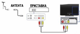
The connection is made as follows:
- Using a coaxial cable, the antenna is connected to an external amplifier (preferably through lightning protection).
- The TV and amplifier are connected to each other in the same way through the input and output jacks.
- The amplifier's power adapter is connected to the mains via a household outlet.
If the TV is installed in a cottage or country house, and the antenna is mounted on a mast, be sure to add an additional element - lightning protection. This device, operating on the principle of a fuse, is inserted into the gap in the coaxial cable. If lightning strikes the antenna, the lightning protection burns out and breaks the circuit. As a result, only the fuse will have to be changed, and not the entire set of equipment, risking, in addition, a fire from a short circuit.
If you need to connect two TVs to one antenna, you need to additionally use a divider (aka SAP splitter, or “crab” in the jargon of TV experts). This device is connected to the cable section between the amplifier and the TV and evenly divides the signal power between the two transmission channels. For terrestrial digital broadcasting, a “crab” with an operating frequency from 5 to 1000 MHz is sufficient.
But you need to remember the following:
- if the amplifier receives external voltage on the network section after the divider, a power pass is not needed;
- if the amplification device is powered from a set-top box or TV, you need not a splitter, but a coupler (TAP) capable of separating the voltage coming outside from the signal coming inside the system.
The number of connected objects in this case depends on the number of output sockets of the divider. In television equipment stores you can find “crabs” for 8 connections. If a larger number of receivers is required, you will have to build a television network with additional branches, intermediate amplifiers, etc. This work is already carried out by professional television technicians.
Option No. 2
If an SWA (feeder fed antenna amplifier) board is used, the circuit will look like this.
Connection is made in the following order:
- Connect a cable between the antenna and the separator that separates the external signal from the operating voltage.
- Connect the power supply. This is necessary if the amplifier is not receiving power from the receiver or receiver.
- Connect the separator to the TV receiver.
If you need to connect two or more TVs, then the signal after the separator can be sent to a splitter.
Option No. 3
In the event that there is a main amplifier at hand, then the wiring principle is similar to the past, but with nuances.
Connect the equipment to each other in this order:
- Connect the passive antenna to the lightning protection.
- The signal passing through the fuse goes to the main amplifier, and then is fed to the separator unit and then to the TV or set-top box.
If necessary, a divider is then connected to the required number of sockets.
Below is a short but succinct video instruction on the correct wiring of all components.
Check the result using a multimeter
Once the circuit has been designed and connected, it makes sense to test it and check the characteristics of the resulting design. To do this, you need to have a tester - or any other similar device.
Check the following settings:
- The characteristic impedance of the cable should not exceed 75 Ohms.
- The difference between the braid of the coaxial cable and the central core should be several tens of ohms. If the device shows “0”, it means there is a break or short circuit.
- When connecting the central core and braid, the device should show infinity, that is, the maximum of the scale. But if both the braid and the core are disconnected from the antenna and shorted to each other, the result should be zero.
If all 3 tests are passed, then the amplifier is connected correctly.
Wiring of the built-in amplifier SWA
A passive antenna can be amplified by installing an SWA card on it. The most delicate place in this process is the wiring of contacts. The video shows the entire process from choosing an amplifier to its correct installation. Just follow the recommendations and success is inevitable.
PreviousNextDid this article help? Rate it Loading...
Source: https://ProDigTV.ru/efirnoe/antenna/kak-usilit-signal