In the modern world, a person cannot imagine life without the Internet, with the help of which you can not only always stay in touch, but also work without leaving home. Due to the imperfection of mobile data transmission technology, frequent failures may occur in the system, so the most convenient way to access the World Wide Web at any time is to use a 3G modem.
Using this device, you can catch Internet signals transmitted over mobile networks while being in any place: in a park, in a country house or outside the city. The quality of transmission will depend on the signal strength, so the issue of enhancing mobile network reception using a homemade antenna for the Internet remains relevant.
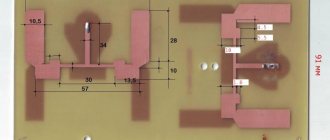
Panel 4G antenna
To make the panel you need to prepare the following parts:
- sheets of galvanized iron measuring 33.4 x 29 cm (for the panel) and 11.8 x 7.05 cm (for 4 patches);
- copper wire with a diameter of 2 mm;
- a circle of copper foil with a diameter of 21 mm;
- 4 pieces of thin foam according to the size of the patches;
- glue for attaching patches to foam.
Patches are arranged in 2 rows of 2 pieces. 2 pieces of copper wire are soldered to them crosswise. A hole is drilled in the panel through which the antenna cable is threaded and soldered to the wire. The patches and the panel are connected to each other through the foam using glue.
The procedure for manufacturing a 4G panel antenna according to Soviet drawings under the code F-20 is presented in the video below. The following materials will be required:
- rectangle of foil PCB 43 x 20 cm;
- 8 M3 bolts and 32 nuts for them;
- transparent printing film for inkjet printers;
- photoresist film;
- reagents - soda ash and ferric chloride.
The antenna vibrator pattern is printed on printer film. The textolite is cleaned and degreased. A photoresist film is glued to it using a roller, onto which the template is applied. The photoresist is illuminated with an ultraviolet lamp for 5 seconds (the time is indicated in the manufacturer's instructions for the film).
The exposed areas are frozen, and the areas of the film where the light does not reach according to the shape of the template are washed. The surface is heated with a hairdryer and immersed in a solution of soda ash, in which, after 2-3 minutes, the unexposed photoresist is washed off with a brush. The board is then etched with a ferric chloride solution for 35 minutes and again immersed in an alkaline solution for 1.5 hours in order to wash off the unexposed photoresist film. After this, the vibrator is ready; it is washed with warm water.
In each of the 8 segments of the vibrator, holes with a diameter of 3 mm are drilled in the center. A reflector of the same size as the panel (43x20 cm) is cut out of a tin sheet. The sheet is combined with textolite. Using a drill with a diameter of 3 mm, holes are made in the same places as the vibrator. M3 bolts are inserted into the holes of the textolite board; on the other side of the panel, 2 nuts are screwed onto each bolt. Two nuts and the thickness of the textolite give the desired 6 mm between the vibrator and the reflector. The tin sheet is tightened with nuts.
A cable is soldered to the resulting antenna and connected to the Wi-Fi router via a USB port. The central core is attached to the vibrator, and the braid is attached to the reflector. The router board is connected using hot glue to the back of the reflector. The vibrator is coated with a special non-conductive varnish to prevent copper oxidation.
3G antenna assembly for 2100 MHz
For assembly you will need:
- copper foil, thickness 0.3-0.5 mm
- M6-M10 rod with a thread of at least 45 cm
- 12 nuts for rod diameter
- Coaxial cable – 2 pieces of 10 meters each
- Pigtail adapter – 2 pcs.
- TV connectors – 2 pcs.
- Screwdriver with drills
- Soldering iron with solder
- Scissors
- Pliers
You will also need an accurate ruler, a marker and electrical tape.
Step No. 1 - preparing elements for the antenna
1 In order to accurately cut circles of the correct geometric shape, you must first center the workpiece, i.e. drill the centers of the circles, and use a compass to make markings along them.
2 Copper foil can be cut well with ordinary scissors. We take the dimensions according to the diagram in the photo below.
Accuracy with an error of no more than 1mm
3 Next, we mark the connection points between the antenna and the coaxial cables. To do this, we mark the penultimate circle R74 - we retreat 11 mm from the circle. You need to make 2 such marks, and they should be strictly perpendicular to the radius.
11mm – 2 pcs., strictly perpendicular to the radius
4 Using a screwdriver, drill holes in the R74 circle for the central core of the coaxial cable (2 mm). Then we place this circle on the R100 circle, and through the holes with a marker we make marks for the holes for fastening the TV cable.
It’s easier to mark in place
5 Drill the R100 and screw the connectors into the resulting holes as shown in the photo below.
Remove excess from the connector
We fix the connectors in the circle R100
Step No. 2 - antenna assembly
We try to make it without errors
1 Using two nuts, fix the R100 circle on the rod in accordance with the dimensions indicated in the photo above. Don't forget to tighten the nuts properly.
Tighten the end nut
2 In a similar way we assemble the entire structure.
Step No. 3 - connecting the antenna to the adapter
Putting the cables in place
1 Strip the ends of the coaxial cables. Insert into the prepared connectors. The central cores of the cables must fit into the holes (2 mm) of the R74 circle.
A little flux and solder
2 Solder the central cores to the second circle (R74).
3 You cannot bend the ends of the central core, as this may result in a loss of antenna power.
Let's leave it as it is
4 The antenna is ready, all that remains is to connect it to the adapter. For this purpose we use Pigtail adapters.
Pigtail adapter
Communication range
The following factors influence the radio range:
- Location of BS and MS and terrain.
- MS power and sensitivity.
- Power and sensitivity BS.
- Antennas used on MS and BS.
- The will of the Lord God (experienced signalmen joke that this is the main thing).
Typically base stations have a power of 20 - 30 W. Antennas are used either whip or directional. The sensitivity of base stations is -100 dB - 115 dB. The user, of course, cannot change or influence all these parameters. The output power of the phone is 0.3 - 2 W, sensitivity - 90 - 105 dB. The sensitivity of a phone is mainly determined by the technologies used to create low noise input devices. If in areas of reliable reception the difference in sensitivity and power between models is almost unnoticeable, then in an area of uncertain reception it can become critical. Often the handset shows the signal level from the base station as 1 - 2 cubes (on the scale), but cannot establish a connection: there is not enough power. And although the ETSI standard regulates the standard output powers for each class of phone, the actual value may vary slightly. Tubes from SAGEM, Alcatel, and Motorola have good sensitivity. And all old phones pass in terms of power, especially Motorola. All phase 2 phones have approximately the same power.
As for the terrain, waves travel better on flat terrain and along the river. The higher you are (within reason), the better the signal. The forest sometimes dampens the waves more than urban buildings.
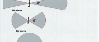
Wi-Fi antenna range
The signal from a native 2 dBi antenna with a frequency of 2.4 GHz using the 802.11n wireless technology standard can travel up to 400 m if the transmission surface is visible and does not contain any obstacles. If we talk about older standards, their signals propagate much worse, although they have a similar range and frequency.
If we consider the antenna that distributes the Wi-Fi signal as an ideal isotropic emitter that distributes electromagnetic waves in all directions at 360°, then we can easily convert the amount of dBi into a powerful increase.
dBi itself (decibel (dBA) isotropic) is a numerical characteristic of the antenna gain, defined as a ten times ten algorithm, the ratio of the amplified electromagnetic field to its original value.
Note! To determine distances, there are corresponding tables that show over what distance in kilometers or meters a conventional directional transmitter can propagate its signal
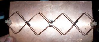
DIY Kharchenko antenna for 4g modem
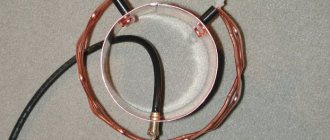
The device is named after the engineer who first came up with it. This powerful external antenna for a 4g usb modem is made by hand; the diagram for the desired option can be found on the Internet. We will give the simplest one.
You will need copper wire and a 2mm thick aluminum sheet. First you need to bend the wire so that its sides do not touch in the middle. And solder the ends.
A hole for the cable is drilled in the center of the plate.
Then the wire is attached to the platinum. It should not touch the reflector.
Distance 3.6 cm.
Next, it is attached to the satellite dish bracket or simply to a stick.
If the modem has a connector for an amplifier, then all that remains is to connect it. If not, then you also need to prepare it yourself. Need copper foil for printed circuit boards. Wrap the modem 2/3 of the way around. Solder the cable. Make a second layer. And secure it.
All is ready!
You can also read the review of 4g Mimo antennas and find out how to set up 4g on your phone.
How to make an antenna for modems
To create a Kharchenko antenna for a 4G modem with your own hands, as well as to amplify the 3G signal, you can get by with the smallest set of devices and accessories that any home craftsman has. Required:
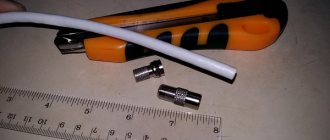
- a piece of copper cable (30 cm), you can take it from the store if necessary;
- a small piece of coaxial TV cable (1−2 m);
- plastic water bottle cap;
- a tin, a piece of foil or a DVD that has exhausted its capabilities;
- ruler, pencils or markers for marking;
- knife or scissors for cutting cables;
- pliers or small vice for breaking the wire;
- soldering iron for connecting cables to contacts;
- glue for plastics (any will do).
If there is no glue, you can make it yourself. To do this, you need to dissolve ordinary polystyrene foam at the bottom of a glass container with gasoline or acetone.
Antenna for the Internet at the dacha
The most common Internet option in rural areas is mobile. To increase the signal level and distinguish it from interference, owners of summer cottages use various types of antennas that allow them to establish uninterrupted radio communications. 3G and 4G coverage areas are available almost everywhere, but there may be problems with stable radio communication due to obstacles that degrade the signal.
The operating principle of all radio signal amplifiers is the same, but the design and technical characteristics differ from each other. Externally and in their use, they do not differ from ordinary television ones, they are only divided according to the power of receiving radio waves. The main characteristic of the antenna is the operating frequency. You need to find out which signal is the strongest in a particular place in order to determine the range of the radio antenna for the Internet in the country. A weak 4G signal can be preferred to a stable 3G.
Note! An external antenna for a computer for the Internet must be mechanically strong, resist wind, and be resistant to high humidity and temperature changes. To strengthen a weak signal, use a radio antenna that is pointed at the nearest base station
The higher it is raised above the ground, the faster the signal will be received. It is securely fixed in a position where signal reception is best, and it is easily accessible so that it can be corrected
To strengthen a weak signal, use a radio antenna that is pointed at the nearest base station. The higher it is raised above the ground, the faster the signal will be received. It is securely fixed in a position where signal reception is best, and it is easily accessible so that it can be corrected.
Moving the signal amplifier outside the building eliminates attenuation and reflections that are created by various parts of the house:
- a powerful 3G/4G signal from a cellular operator’s base station is picked up by a radio antenna, which is located on the facade or roof of the house;
- the signal is transmitted via cable to the modem, which is inserted into the router;
- The router distributes the Internet via a LAN cable, Wi-Fi to the N number of subscribers.
3G Internet at a distance from the base station using a plate and a coffee can
Hello to all residents of Habr!
The essence of this article is to show another option to catch the E/M wave by the ears in the relative outback for the needs of Internet access. If somewhere exactly such a design has already flashed, you are welcome to link it, it will be interesting to compare and chat. I will present the material in a narrative form, I hope I won’t torment anyone too much with this, all sorts of terms, if someone doesn’t know, and other details can be safely skipped, this will not change the essence of the post much.
Formulation of the problem
The Internet is a useful and necessary thing, I think it’s hard to argue with that. And if there are no problems with the Internet in the city, then in the village, where I often have to go for family reasons, there are certain problems. There is a private wooden house a la “hut” (location: RB), 3 operators provide access from the Internet in my vicinity, but the maximum is only EDGE technology. The two nearest base stations (BS) are about 3.5 and 7 km. There is a forest between the house and the BS, but not close. EDGE would be enough, but the load on these stations from other neighboring villages, judging by the speed, is such that you can “hide in potatoes.” The option to buy a ready-made solution was eliminated immediately for reasons of sporting interest. Inspired by the successful experience of the guys on one of the forums, where they used a satellite dish (aka “offset mirror antenna”) and the 3G modem itself in focus, I decided to simulate and twist something similar. I’ll say right away that I wanted to throw the antenna with the modem into the attic so as not to spoil the appearance of the house (more on this below).
Shopping, modeling, measurements
The first thing I did was look for a larger mirror.
I agreed with the toad on a Ukrainian mirror “Kharkov” with a diameter of about 85 cm, because for those that I have seen larger than 1 m, the price tag is already somehow non-linearly soaring. Using a map of the operators' coverage area, I found that the nearest point with 3G is about 21 km. The terrain up to the BS is not mountains, but, again, there is plenty of forest. The first experience was in winter. There was no bracket, so I tried to position the antenna as best I could. I tentatively set it to the supposed BS with 3G, but no matter how I twisted the mirror itself and oriented the modem in the focus area, it didn’t work out, sorry. Although the beamwidth (to put it simply, the “beam width”) at 2.1 GHz is quite wide, this is not digital satellite TV on the Ku band, where try to “hit” this satellite. The reasons are as follows. The pattern in the modem is calculated to be as isotropic as possible, so part of the power goes not to the mirror, but to the opposite side, and the antenna itself on the modem board, in its ability to catch something weak, leaves much to be desired, this is logical. The BS and the antenna are separated by a wooden roof panel, which also provides a certain attenuation. I even came across some interesting literature on this topic, mainly on the topic of wood drying. Quite entertaining, but with a bunch of formulas from electrodynamics characterizing the dielectric properties of “pieces of wood”. What is useful, first of all, is that the attenuation coefficient depends on the orientation of the fibers in the board in relation to the polarization of the wave. I hadn’t thought about it before, although it’s also logical. But no luck here either: the boards in the shield are all vertically positioned - maximum attenuation. In general, there was a desire to tinker, but there was no opportunity (you can’t sit in the attic with a laptop on the battery for a long time) and no health (temperature -> like outside => hands are freezing).
A little upset, I decided to act according to the classic scheme: a homemade feed source - at the focus of the mirror, a coaxial cable from the modem to the feed source. Regarding the irradiator, there were thoughts about what to take: some kind of rectangular waveguide, or a round one. I settled on a regular tin can. In the west it is called “Cantenna”. Nothing original, there is enough experience on this miracle on the Internet. I tried, like some, to simply stuff the modem into an old can at the point where the probe is usually placed in the waveguide and thus irradiate the mirror, but that was also unsuccessful.
As a result, having determined the diameter of the jar with the condition that one mode propagates at its frequency (~2.1 GHz) in a round waveguide, I went to the store with a ruler (!) to buy the jar. Before that, I still had to dig a little on the Internet to find out what frequencies we have deployed UMTS on. I finally found the one I needed, 10 cm in diameter. I bought two, for which I received verbal criticism from my relatives, although I bought it, sort of, for my own. The coffee wasn't cheap.
In addition, I had to buy an SMA connector for a nut so that the can could be disconnected from the modem. I modeled the antenna system and the feed separately on the computer, and went to cut up the jar. This is where you need to be quite careful with the sizes: the characteristics are sensitive to mistakes.
The figure below shows a model of a can, in which there is a random copper tube (a thick cylinder tapering towards the bottom), sealed at the terminal of the SMA connector.
This is what happened with the simulation (CST). Gain based on simulation results: 22 dBi. The following shows a general view of the entire offset antenna, which is familiar to many, + 3D pattern.
The characteristics of the antenna itself were not measured, only the SWR at the SMA connector directly on the can. The graph shows the curves S11 (reflection coefficient in dB). The green curve is an experiment (in theory, it can also be used at frequencies of 3.4, 4.5, 5.5 GHz  ).
).
I was pleasantly surprised that it coincided quite accurately. For me, the SWR is good: all the power from the antenna opening goes into the cable (and vice versa).
But then the saddest thing began. At first, I wanted to use the Huawei E303 I once bought in the store, soldering it directly with a cable, because... modem without external connector. Having found a rather small connector on the board (U.FL, most likely), I tried to solder the end of the RG174 cable in its place, because... I didn’t even try the cable connector in our retail stores. The idea was, frankly speaking, idiotic - I had little experience, although I used a soldering station. The RF path of the modem was covered - it became a kind of USB-microSD adapter. In the photo it is still intact (the photo is for reference if anyone is interested, I looked for the E303 on the internet, but couldn’t find it).
So to him: how much I suffered with it with switching to modem mode, and not a network card, in order to see the signal level in numbers (it even got to the point of using Linux). Well, somehow the numbers turned out. After a while, kind people gave Huawei e173 with a connector, but with a broken USB plug. Glad that I have now unsoldered the connector from the old one and soldered it into the new one, I discover that the contact pad on the board on the signal pair has been torn off, and under the microscope I was able to see only the point of the via jumper. "Lucky." But the world, again, is not without good people: they soldered the MGTF “hair” onto this jumper (surprisingly, the solder stuck) and soldered the connector. The modem started working. The pants were full of happiness. Now we needed a CRC-9 connector. After a trip to the radio market in Minsk, the only thing I found was the “CRC-9 – FME” cable (the same as in the photo below). I had to solder FME to SMA.
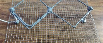
Testing
Finally, in the summer it was time to test what happened. In the garden, under the apple trees. On the left in the photo is a blue and red can of coffee, with a modem taped to it, and the above-mentioned cable from the connector on the modem to the connector on the can. The photo on the right is from a different angle. Behind the hill there is a continuous forest. Turning the antenna, I found two points. In one the signal is worse (the result of the MDMA program), at a level of -103 dBm (the forest is closer, or the channel is worse, or the BS antennas shine weaker in my direction, I didn’t understand), in the second it is better -93 dBm. Note that this is all from ground level! The second photo shows the direction to the second BS (the distance is a little more than 20 km, according to the netmonitors, for which special thanks to them).
Speed test from under a tree
By the way, it’s very funny to talk on Skype in video mode while sitting under an apple tree.
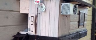
All that remains is to pile it all up in the attic. But there is one more problem left to solve. I didn’t want to run 220V into the attic in order to install a router to power the modem. Since long USB cables are not cheap (I needed > 7 m), I had to solder a USB extension cable using twisted pair (I had a chance to buy SSTP 6 cat, I was terribly glad, I used it for greater reliability, although it is also not cheap). There is plenty of information on the Internet about how to make a USB extension cable from twisted pair cable. Having drilled a hole in the ceiling, I lowered the cable into the house. Well, whatever your imagination allows, even Wi-Fi. The signal in the attic floats from -87dBm to -93dBm. But this is not critical. On the left is a speed test in the attic of the entire system. And on the right is what the modem provided on its own in the attic from nearby BS (2G) (even ICQ was slow).
Photo from the attic. On top is another antenna - UHF (DVB-T). The part of the photo where the window is is the shield discussed above.
And the photo of the can is a little closer. Has anyone ever received a Nobel Prize for scotch tape, or not?! If not, then it's a terrible mess!
I hope the information will be useful for someone to think about and will bring civilization closer to your God-forsaken corner. I ask for constructive criticism to the studio. If you have any questions, I will be happy to answer.
What is the Kharchenko antenna and how does it work
The so-called Kharchenko antenna, which is intended for a 3G modem, is a homemade model. There is nothing particularly complicated about its design. The zigzag design was proposed by scientist K. Kharchenko back in the 1960s. Today it is quite popular among radio amateurs not only due to its simple design, but also excellent repeatability and broadband. This last advantage applies particularly well to the spiral design.
In terms of their design, models can differ quite significantly. Based on the size of the plate, the frequency of the structure changes significantly. At the same time, you need to take into account that homemade antennas may include objects made of plastic and metal.
The antenna for the modem comes in different types. The simplest one is omnidirectional. It can receive and transmit signals in all directions equally intensively. In particular, this could be a simple quarter-wave vibrator. To put it simply, this is a piece of wire that has a length of a quarter of the wave of the signal that is being received.
A sector antenna can limit radiation in a specific sector. In particular, if you place an iron sheet behind the omnidirectional device, you get a sector design. Its sector will be 180 degrees. Such an iron sheet is called a screen.
The most effective is a directional design. Thanks to the correct choice of screen curvature, you can create a narrow beam that will emit a radio wave.
The main antenna units are:
- a vibrator that induces, induces, a wave of electromagnetic oscillations that are sent by the cellular operator’s transmitter;
- a cable together with a matching unit that transmits the induced signal directly from the vibrator;
- signal transmission unit from the cable directly to the modem input;
- a reflector that eliminates interference as well as reflected signals to increase receiving power.
The DIY Kharchenko antenna is an excellent device for anyone who wants to have high-quality communications without having to spend large sums of money. It is very easy to make even for an ordinary person who does not have the appropriate professional skills. The result is truly excellent. This design will last for a long time.
Design issues for LTE antenna Kharchenko
According to the theory, which is not easy to find in a book, the diameter of the frame wire should be 0.016 - 0.02 of the maximum wavelength. For television frequencies from the times of the USSR it was:
- 1 – 5 (49 – 100 MHz) channels: 120 – 100 mm.
- 6 – 12 (174 – 230 MHz) channels: 34 – 27 mm.
It is difficult to find a wire of significant diameter; it was proposed to replace the round conductor with a flat one. The windage of the antenna has increased significantly, which cannot be called a positive factor, manufacturing has become more complicated, the weight has increased, and materials have become difficult to obtain. Three circuits are used. Good news: we will work with frequencies of 750 MHz and higher, everyone can get a wire with a diameter of 6 mm (stripe the PV). The second good news: we found a way to do the installation. The unknown author took the trouble to copy the drawings from the book and provided a description of the process on the website https://chegdomyn.narod.ru/meny/radio/ant-xarchenko.html. Free domain, so 99% of the information was obtained by a dedicated enthusiast.
The authors were too lazy to retake the drawings, let’s add a few words: two semicircular plates are placed on the sides of the circuit board, onto which the wire is soldered. At the corners (6 pieces in total) the frames are bridged with metal strips. They were right about the trajectories. Follow the picture, you can't go wrong. It is not customary to insulate the intersections of the wire; the antenna cord does not need this at all.
DIY antenna made for LTE. How to coordinate was written in a special review called DIY Kharchenko Antenna. Today, WiFi enthusiasts widely use the design. Sometimes they place the iron in a plastic case, finishing the seam with silicone sealant purchased at a plumbing store.
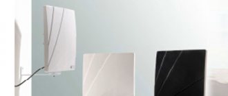
Application of panel antennas for operation in 4G networks
An outdoor LTE panel antenna is most often used to improve the quality of data exchange in areas with poor reception.
Small dimensions and high technology make it possible to place a large number of elements in one housing, which is especially important when using MIMO technology
MIMO technology
MIMO technology allows you to increase the throughput of a data transmission channel to the maximum theoretically permissible value. This technique produces spatial encoding of the signal due to the fact that reception and transmission are carried out by different antennas. The main requirement for successful use of MIMO technology is that the coupling between antennas should be as weak as possible. Technical language says that the antennas should be weakly correlated.
MIMO antenna
Equipment that supports MIMO divides the signal into several streams, distributing them among users. If there are fewer users than the number of transceiver modules, then each client can receive a signal through several streams.
So the following happens:
- Data transfer speed increases;
- Noise immunity is increasing;
- Traffic interception becomes more difficult.
MIMO technology requires both provider and customer equipment to support it.
LTE standard, LTE antennas
We avoid exploring the wilds of LTE. Let's mention simple facts: speed increases faster using information encoding methods and modulation methods. The polarization is almost certainly linear, vertical (typical of cellular communications). The frequencies adopted by LTE are not always respected in practice. The thesis concerns Russia. First of all, find out the wave (channel number) from your provider, then start constructing an LTE antenna. Today, every mobile operator broadcasts. In the Astrakhan region, LTE is distributed to two or three antennas. Everyone’s frequencies are different, the numbers change by region, and things are heading towards the fact that communications will become faster and cheaper.
We bring to the attention of newcomers: there is always a war for the frequencies of LTE operators, as well as television and radio companies. The range is not provided for free, the company is obliged to pay. The state benefits from the abundance of LTE operators - everyone waives the fee. It’s not new that large enterprises using walkie-talkies replenish the treasury with considerable sums. It’s difficult to say what LTE is paid for, but we believe it looks like this:
- Radio waves are harmful to humanity. Definitely a proven fact. They lower immunity, provoke poor health, and raise body temperature. The person feels completely sick and has been exposed to radio wave radiation.
- Therefore, the organization must take control so that citizens are not irradiated. Otherwise, the population will start to get sick, and nothing good will happen. The committee is GRKCH, if you are interested in more details, read the thematic reviews of the network for your health. The organization is engaged in frequency distribution.
We believe that the fees paid by LTE providers and other users of radio channels do not bring much profit (professionals will forgive the editors if we are mistaken). The money pays for the work of people who need to be paid salaries, sick leave, vacation pay... The state does not receive much profit from LTE. Don't be surprised if you can't catch operators with one LTE antenna. The range is considerable.
However, today we will show you how to make an LTE antenna that can catch everyone. Of course, you will have to sweat a little. We strongly recommend reading the literature, the book by Kharchenko K.P. 1969 release about VHF antennas. The title may be different, we believe that persistent readers will be able to download and read this work (pdf, djvu versions are posted).
Features of LTE antennas are limited by size. Suitable for GSM too. WiFi lies above. The LTE antenna picks up the upper television channels if you turn it so that the figure eight becomes upright (rotate 90 degrees).
Simple external 4g antenna with your own hands
When thinking about how to make an antenna yourself, you need to evaluate what raw materials are available in the house. If a consumer of Internet services has a case from a computer that has fallen into disrepair at home or in the country, you can use it as the basis for an antenna. You will need to purchase a USB cord for a signal amplifier and scissors for cutting iron from the store.
You will need to cut out a structure from the back wall of the case, which is based on a rectangle 24 (width) by 20 cm, from which a thin long part 7 (width) by 14 cm extends down. In this “leg” a square hole is made for the cable (2 by 2 cm), as well as holes for a thin metal bending structure (the dimensions of the latter are 23 cm long by 2 wide), cut from the same body, and for a locking bolt. The scheme for cutting the body into components is very simple; the corresponding marks can be made with a pencil.
Is it possible to make an antenna for 3G and 4G yourself?
Some people think that it is impossible to make an Internet amplifier at home. Such people believe that for this you need to be well versed in physics and radio engineering.
In fact, even a person with scant technical knowledge and without special practical skills can make an antenna on their own to improve network reception. However, despite this, you will still have to familiarize yourself in advance with the step-by-step instructions for making such receivers and the features of their operation.
Description of a homemade receiver
With appropriate settings, this antenna is both an amplifier and a receiver. The inventor and scientist Kharchenko suggested using this biquadrat as an antenna. Biquadrat is a subspecies of loop antennas, which are primarily classified as zigzag.
K. P. Kharchenko proposed this device as an antenna in the middle of the last century (1961) for use as a television receiver. There is a good reason for this: it is a historical, recorded fact that, having tuned his antenna to a frequency of 14 megahertz and giving it the required position, the scientist received a signal from America.
Among the factory models of amplifier antennas, it is easy to find powerful devices with high performance. But quite often you can get by with a simple design that can be easily assembled from available materials with your own hands. It is enough to use the well-known development of Kharchenko.
According to the creator’s research, in terms of output parameters, the antenna reliably enhances the operation of digital devices operating on mobile platforms, generating an increase in signal reception of up to 3-4 dB, even without the use of a reflector, and with its implementation - up to 8-9.
Homemade biquad antenna
The pioneers among homemade biquad emitters for wireless signal propagation were samples back in 2005. The best modifications of these devices were biquadrate, which produced a signal power of up to 12 dBi, and biquadrate with a value of up to 14 dBi.
If we take into account the multifunctionality of the device, then it is preferable to install a biquad design. This equipment will make it possible to maintain the width of the signal opening angle while compression of the radiation field is inevitable.
Details for making a biquad emitter:
- For the reflector, foil PCB measuring 12.3x12.3 cm is useful;
- Copper wire with a cross-section of 2.5 square meters. mm;
- Coaxial cable with BC 50 Ohm;
- Connector with N type output for connecting the antenna itself.
In general, the device will look like squares connected by corners with diagonals located on the same straight line. Looking at the photo of the wi-fi antenna, you can see a biquad emitter and a grounded reflector. The top of the device should be adjacent to the cable, and the bottom should be adjacent to the ground.
The reflector is a piece of highly conductive material. Aluminum, steel or tin cope well with this task. In some cases it is easier to use a CD.
Reasons for poor internet on your phone
If a user on his phone encounters problems with Internet speed, then this may be a consequence of certain factors. Some of them depend on the location.
If the connection speed is weak, then the reasons for this may be the following:
- Exceeding the permissible mobile traffic limit, as a result of which the speed will be reduced until the end of the day or month by the operator, depending on the tariff.
- Weak cellular network signal, as a result of which it does not pick up the 4G/3G network. Currently, the 3G coverage of mobile operators is quite good, in contrast to the 4G standard, which is still being introduced.
- Uneven terrain in which the subscriber is located. Hills, mountains, ravines and forests, as well as all kinds of concrete obstacles, greatly reduce the quality of the transmitted signal.
- Any operational errors, viruses or glitches.
- Long range to the tower.
Important! An Internet antenna for your phone can help strengthen a poor signal if it is caused by long distances and uneven terrain.
Installation
The easiest way to attach the antenna to a block is by drilling holes in the “trough” between the central vibrators and fastening it with screws or screws. If you plan to mount the antenna on a pipe, it is better to rivet an aluminum corner about 30 cm long to the antenna on the back side of the reflector, then attach the corner to the mast using clamps or ties.
Thanks to the forum participants for the information provided.
Wireless data transmission technology has become an integral part of life in the modern world in recent years. Many users who install a Wi-Fi system at home are faced with the problem of a weak signal. The WiFi antenna is not always the problem. Almost everyone can do it with their own hands, but before starting assembly, it is necessary to exclude other factors that affect the signal level.
Protection
To protect from external influences, the remote antenna must be placed in a housing of suitable dimensions. The exit points of the cable and fasteners must be carefully sealed.
Important! The body of the structure must be made of non-conductive material. It can be polystyrene or polyethylene
The first material is preferable because it allows the body to be assembled by gluing and is sufficiently resistant to ultraviolet rays, low and high temperatures.
External devices are at their greatest risk during a thunderstorm. A lightning strike that hits an antenna can instantly damage the internal circuits of all equipment connected to it. Therefore, if there is a possibility of a thunderstorm, you should disconnect the antenna cable from the modem or router connector.
Homemade devices for increasing the received signal power can improve the quality of reception, the speed of reception and data transmission, eliminating additional costs for more advanced equipment.
How to connect a homemade antenna to a phone, tablet or modem
Half the job is done. All that remains is to connect the antenna to one of your home devices. It is worth understanding that the method below is not suitable for all types of equipment.
Note! To implement this, you need a special diagnostic port. If the phone cannot be disassembled so easily (the same goes for modems with tablets), then nothing may work out.
Outwardly, it looks like a round yellow connector. What needs to be done? Everything is elementary:
- Take a thin wire or antenna cable.
- Insert it into the connector.
- Place it along the body so that it does not interfere with the closing of the lid and the battery.
Important! In the case of a portable modem or router, you will have to disassemble the device case and find the port on the board.
Characteristics of external amplifiers for the modem
The main parameters characterizing the operation of an external antenna should be considered susceptibility, which determines the quality of the captured signal, and gain, which describes the signal redirected by the device. Both of these quantities are supposed to be measured in dBi.
Important! The characteristic that describes how sensitive an antenna is is a negative value (as opposed to gain). What unites these quantities is that the large value of the modulus of the number is highly valued
For example, a sensitivity of -85 dBi would be preferable to -70. In turn, a coefficient of 10 dBi is valued higher than 5.
Settings
The setup method is similar to how a satellite dish is installed on a television satellite. On the Internet it's a little different. The plate must be directed lower. You may even have to point it down. This is due to the curvature of the reflection. To set up a satellite dish as efficiently as possible, you need to rotate it and use a special program to monitor how the Internet connection changes. Once you are sure that you have obtained the maximum value, the antenna must be fixed.
The external 4G antenna is fixed, now we can move on to the next step. Now it's worth experimenting with focus. For different modem models it is necessary to configure the converter holder differently. To do this, you need to change the focus position and monitor the quality of signal reception.
In order to correctly adjust the focus, you need to know that the modem antenna is on the opposite side from the USB. Of course, this is not the case on all models, so it’s worth disassembling it to understand where the receiver is.
If you have not achieved line of sight conditions, then you should raise the structure. Increasing the diameter of the mirror can also help improve signal quality. A 4G directional antenna is capable of picking up signals over a long distance. How is diameter related to reception quality? On average, a dish with a diameter of 1 m provides a fairly good Internet connection at a distance of 30 km from the station. To connect the modem to your computer, you need to buy a USB cable. What should it be like? Of course, you should use a high-quality cord, a small cross-section with shielding and ferite at the ends. You can also purchase several of these cords and connect them together, without losing quality.
It should be remembered that you will not be able to use a satellite dish for television and strengthen your Internet connection. Of course, you can attach the modem to a satellite dish to boost the signal a little. But it should be remembered that if the dish is tuned to TV, you do not need to turn it away from the satellite. A high-quality signal can be obtained if the satellite dish is configured for line-of-sight conditions.
How to assemble a WiFi antenna
With our own hands we cut out a square plate with a side size of 110 mm from a textolite plate. We drill a hole strictly in the center for the copper tube. The diameter of the hole and tube must be the same. The plate must be drilled from the side of the copper coating. Along the edges of the hole, you need to tin the copper surface with a soldering iron. This will be a reflector. On a copper tube from one edge we grind one side along the diameter by 2-3 mm. We insert the tube into the reflector so that the ground part is on the side of the copper coating. The distance from the reflector to the end of the tube must be 16 mm.
We cut off 244 mm of wire and strip it of insulation. We make superficial cuts every 30.5 mm. After this, follow the marks and bend it at a right angle so that it looks like the number eight.
We solder the free ends to the very top of the tube so that the whole part is above the ground part of the tube. We solder the central wire of the cable to this place, after inserting it into the tube. We have a WiFi antenna. With our own hands, we assembled a structure capable of increasing the signal by 6-8 dB.
Now in amateur radio practice, antennas for amplifying 3G, 4G, Wi-Fi signals of the “Biquadrat” type are very common.
Such an antenna has a directional effect, which may not always be an advantage, but even a disadvantage. An example is this: you need to strengthen the signal of your router so that you can catch it in any part of your house. If you use a directional antenna, the signal will most likely be well accessible only within the field of action of this antenna. Surely there will be only one room where it will be directed. It is good to use such an antenna only for long-distance communications, provided that you know where to point it. To strengthen your WI-FI signal in all directions, an antenna is suitable, which I will show you. Its directivity characteristics are close to those of a whip antenna, with the exception of greater sensitivity. In structure, it is actually the same biquadrate, only twice directed in opposite directions. Plus, this antenna is many times simpler than a classic biquad antenna, since it has neither a stand nor a reflector.
Types of external antennas by design
In this case, there are several possible options:
- Parabolic;
- Pin;
- Sector antennas for 4G Internet;
- Circular omnidirectional;
- With wave channel;
- Panel.
Note! Each external antenna for a 4G modem has its own characteristics
Directional antennas (“Wave Channel”)
A characteristic feature of such products is a narrow radiation pattern. The main purpose is to receive and transmit signals while maintaining one direction. Depending on the installation, the effectiveness of two important parameters is determined:
- Radiation;
- Reception of radio waves.
This type requires additional adjustment of special precision
It is important to ensure that you point to the desired station. Only in this case will the device be as effective as possible.
This is how any antennas work to boost 4G, LTE, 3G signals.
Note! Often such structures are also called beam structures. Other names:
Other names:
- Yagi-Uda;
- Christmas tree;
- Wave channel. Another name is the MIMO antenna for a 4G modem with amplification.
Panel antennas
Such devices are among the most common for receiving and transmitting radio signals. A variety of directional models. But the radiation pattern of the panel ones is larger when compared with the previous type. Thanks to this, the process of setting up basic parameters is simplified. It is enough to correctly turn the device towards the base stations to get the optimal result from using the antenna to boost the 4G signal.
The products have three important advantages:
- Broadband;
- Versatility;
- Supports all popular signal transmission formats.
The kit consists of an antenna array, which itself is essentially dipoles located one below the other in two columns. Horizontal spacing is the name given to the method of arranging parts of the structure in this case. In the direction to the base station, the signal quality is constantly improving with this organization. Dipoles can be positioned differently, depending on the polarization:
- X-shaped in both columns;
- Horizontally, with an inclination of 45 degrees;
- Vertical.
Note! The 4G amplifier antenna frames are often combined into a single housing that looks like a flat panel. For this installation, the design received the name
Circular omnidirectional antennas
Suitable for use in conjunction with all current standards for data transmission and voice messages. Any modern technologies are supported:
- LTE 2600;
- UMTS-2100;
- LTE 1800;
- GSM-1800;
- GSM-900.
In this case, you can refuse precise installation in the direction of one or another base station. This is the omnidirectional variety. But their gain remains quite low. Only in some cases will it allow you to increase the signal level from uncertain to stable for a 4G LTE antenna for a USB modem.
Whip antennas
A variety of circular omnidirectional products. An asymmetrical vibration system is the basis for these devices. It is made as a rigid rod made of metal. The round shape has become a distinctive feature for the radiation and reception patterns. When organizing communications between mobile objects, this design option is very convenient. The signal comes from all directions, no fine tuning is required.
Sector antennas
Note! They are used when a base station is deployed, which is characterized by a large subscriber base. Products are designed specifically for operator towers using sector organization
The basis is a phased array circuit, with the formation of a 60-degree sector.
One of the main features of the design remains DC closure. Therefore, sector options are allowed to be used even where particularly difficult climatic conditions exist. The need for additional means for water protection then disappears. Directional 4G antennas cannot boast of such advantages.
Parabolic antennas
A relevant option if the operator’s tower is located far enough - at a distance of up to 20 kilometers or more. The solution has not become widespread due to difficulties encountered with installation and settings.
Note! Powerful parabolic 4G antennas are offset and direct-focus in design
Other homemade antenna options
Ideas for homemade antennas could be the following:
- Colander 4G. Everyone has a simple aluminum colander in their home. You need to fix the USB extension cord on the handle of the cookware. Connect a modem to it - it should ultimately be within the circle of the bowl. We direct the colander to the base station and catch the signal.
- 3G/4G satellite dish. If you have an old satellite dish, use it. The signal will be amplified significantly, since the antenna will be outdoor. Remove the converter from the boom. Secure the modem at this location. Naturally, you will need a USB extension cable - carefully stretch it to the modem and connect it. Now point the dish at the operator tower. To adjust, you will need to rotate the plate slowly to achieve maximum effect.
- Antenna "Double Ring". The method is similar to the Kharchenko antenna. It is just as effective, but here you also have to work hard to make the antenna.
Production of biquadrat Kharchenko
In photographs of homemade antennas for 3G modems you can see its approximate appearance. First, you need to make markings on the copper wire with a pencil: the length of the outer side of each square should be approximately 35-36 mm.
Carefully bend the wire along the markings, helping yourself with pliers. You should get a symmetrical design of two squares touching at the corners. Remove the remaining pieces of wire.
Make a hole in the cover and insert the end of the cable into it. Separate the cable, exposing the inner conductor and shield for soldering.
Next, you should solder the antenna to the cable and connect it to the modem. Soldering proceeds as follows: solder the central core to the middle of the antenna on one side, and the screen on the other. Then move the cover towards the antenna; you can further strengthen and insulate the structure with glue or sealant.
Insert the reflector disk into the wire through the hole, move it towards the antenna and glue it to the cover. Solder the connector to the cable on the other side for connecting to the modem. Connect the antenna to the modem. Enjoy the result of your work!
Technical data and characteristics
Depending on the range, radio antennas have different designs and dimensions. Designs of existing receiving and transmitting devices:
- "wave channel";
- pin;
- Kharchenko zigzag antenna;
- planar.
The directional “wave channel” has the highest gain among all known antennas. If the distance from the base station to the village is several tens of kilometers, then a parabolic antenna may be the only solution for mobile Internet.
The simplest type of pin is a vertical conductor mounted on an insulator and connected at one end to a receiver.
A panel antenna is a version of a radio antenna that catches a scattered signal. When there are any obstacles, this model is suitable for stable operation of reflected waves.
The universal model of the Kharchenko radio antenna, which can be made by hand, consists of two copper squares, 3.5-4 mm thick. Simple in design, the frame model creates an excellent reinforcing effect.
Depending on the connection method
SMA modification
Several conditions must be met for this modification of the antenna for a 4G router to work for the user:
- 3G/4G modems equipped with TS-9, CRC-9 connectors.
- Models with SMA connectors through which external connections are organized. The modem is already built into these routers. All you have to do is insert the SIM card.
- You will need not only the device itself, but also 2 cable assemblies with SMA connectors, up to 10 meters long. Then it’s easy to enhance the signal quality.
- To connect the cable, it is recommended to purchase two special adapters or pigtails.
Note! The use of this technology is relevant if there are connectors where external devices are connected. You can also use adapters to connect to regular USB modems
But a high-frequency cable in such situations will be too expensive. And losses in signal quality will remain serious. We'll have to strengthen
You can also use adapters to connect to regular USB modems. But a high-frequency cable in such situations will be too expensive. And losses in signal quality will remain serious. We'll have to strengthen it.
BOX modification
The purchase of such products requires the presence of the following equipment:
- USB extension cable.
- Modems for outdoor antennas for 4G modems, supplemented with TS-9, CRC-9 connectors.
Important. At the rear, the device is complemented by a sealed box of small dimensions
Adapters for connecting to a modem are usually already built into this part. A modem with 3G/4G technology is installed inside the box, to the connectors of which adapters are then connected. The next step is to insert a USB extension cable into the box. Usually a special sealed lead-in is used. All that remains is to connect to the modem.
A universal WiFi router with a USB connector and 4G support is needed if you plan to use the Internet on several devices simultaneously.
If the user already has a 3G/4g modem, the BOX modification will be an excellent way to save money. Only the modem limits support from certain telecom operators. The overall stability of operation via a USB extension cable largely depends on specific models.
USB modification
This is a kind of ready-made complex that allows you to amplify signals that are transmitted according to conventional standards. The user does not need any additional devices; a standard set is sufficient for amplification.
Note. A universal 4G modem is already built inside from the start
But 3G standards are also supported. It is enough to connect a SIM card from any operator operating in Russia. After this, the device is connected to the computer. Another option is to use a router together with a USB cable 10 meters or more long.
Signal loss on cables when using USB modifications is completely eliminated, the connection is stable.
Note! Only Ethernet modification devices will be a suitable solution if the connection requires a cable longer than 10 meters
Ethernet modification
Another type of ready-made kits that amplify the signal for modern 3G/4G standards. The kit comes with a built-in 4G modem, which is complemented by a router with a POE adapter. This designation is a technology that allows you to connect regular Ethernet cables. Their length, at the user’s request, can reach 100 meters.
When the connection freezes, the device supports automatic rebooting. Characterized by compatibility with WiFi routers of almost any modification. The rating will help you make your choice.
Note! Signal loss on cables is almost completely eliminated, which already distinguishes this option from the SMA 4G antenna
What types of 3G/4G antennas are there?
Antennas (both purchased and homemade) are divided into several types depending on several indicators. If we talk about the installation method, there are indoor or outdoor antennas. The latter are more effective because they work in open space, where there is less interference. They are suitable for those subscribers who live far from the tower.
Indoor antennas are not as effective as outdoor antennas
Based on the receiving signal, antennas are divided into broadband and narrowband. The first ones are more functional - they are capable of receiving 2G and 3G signals when, for example, 4G does not work.
Antennas are also divided into directional, omnidirectional and sectoral. The last two types are capable of catching signals from several towers at once. There are also conventional devices and MIMO antennas - advanced equipment with two antennas at once, which receive the signal separately from each other, but transmit the signal to the modem simultaneously. They can increase speed up to 100 Mbit/s.
The MIMO antenna essentially has two receivers, hence its effectiveness
Depending on the presence of an amplifier in the antenna, devices are divided into active and passive. Passive ones, where there is no amplifier, do not improve the mobile network signal as much as active ones, but they do not need to be connected to an outlet (the amplifier is powered by an electrical network).
Installing and connecting a Wi-Fi antenna
Before installing the Wi-Fi antenna, you need to decide on the place where it will be installed and check the presence of fasteners. If the necessary accessories are included in the kit, the antenna is mounted in compliance with the following basic rules:
- For the best signal quality, it is recommended to install a room amplifier within the direct line of sight of the router;
- take into account the presence of obstacles (walls, ceilings, furniture), and even better - place the antenna above the level of the furniture. The ideal option for a living space is ceiling antennas that look like a flat lampshade;
- Do not install the antenna near windows and mirrors. They are able to reflect the signal, forming dead zones behind them.
- For external antennas, check for built-in lightning protection; if not, purchase a separate special device. Homemade devices without a lightning rod should be grounded.
After installation, the antenna is connected to the router or access point. The connection type depends on the router model. If the router has removable antennas, then by unscrewing them, you can free up the connectors for connecting a factory or homemade amplifier. You can also simply connect the amplifier to a router that has a special socket for an external antenna. Additionally (if the connectors turn out to be incompatible), an adapter or a so-called N-type connector may be required.
Depending on the design of the antenna, it can be connected to the router directly via a universal SMA connector (MMCX) or using a cable crimped with an N-Male connector and connected to the N-Female antenna connector. If such a cable is not included in the kit, you can make it yourself using an RG-6U television cable and an N (Male) to F (Female) adapter.
The high-frequency adapter for the Wi-Fi antenna is equipped with an N-type (male) plug on one side and an F-type (female) socket on the other.
It is much more difficult to connect an antenna to a router that does not have an outlet for an external antenna. In this case, you will have to unscrew the router case, remove the soldered standard antenna and solder a new one in its place. Performing these manipulations requires certain knowledge and skill, but it will eliminate the need to select connectors and adapters.
When the antenna connection process is completed, all that remains is to configure the router to work with an external antenna. To do this you need to do the following:
- Download and install the specialized WinBox utility on a PC or laptop connected to the router.
- After launching the program, go to the section Wireless → Wireless Tables → Interface in the side menu, where you select the wlan 1 connection.
- In the window that appears, go to the HT tab.
- In the drop-down list opposite Antenna mode, select antenna b mode.
- Save the settings and reboot the router.
After this, the external antenna will work in parallel with the standard antennas of the router. If you wish, you can turn off the router's antennas, leaving only the external one to function. To do this, in the HT tab you need to uncheck the chain0 fields and then save the changes.
Having completed setting up the router, you can begin testing the antenna. This process can be performed manually or using programs designed for this. During manual testing, the signal strength and Wi-Fi connection speed are checked after each antenna rotation or tilt angle change. When using utilities such as the Homedale application, information about Wi-Fi network performance is collected automatically. Among the parameters displayed in the program window, the main values for the user are the Signal Strength (signal level in dBm) and Bitrate (data transfer rate in bits/s). The lower the Signal Strength value and the higher the Bitrate, the higher the quality of the signal.
Homedale detects all access points that are within range of your Wi-Fi device and displays their status and signal strength
When using a Wi-Fi router at home, users often encounter that the wireless network signal is unstable or does not reach some rooms. Connecting an additional device in the form of an external antenna will help correct the situation. By choosing the right type of antenna (directional or omnidirectional), you can not only strengthen the signal, but also significantly expand the coverage area.
Device creation process
First you need to create a vibrator. Size and symmetry are of paramount importance. To give maximum symmetry to the installation, it is necessary to make all the edges of the squares absolutely identical. This can be achieved in two ways:
- Be sure to pre-mark the wire with a marker;
- apply a control template of a certain length.
In the first method, pliers are placed on the wire marking and the latter is bent at an angle of 90 degrees to control the bend along the square.
In the second case, it is necessary to separate a part of the wire on a scale slightly larger in size than the sides of the square, and then sharpen it with a file or coarse sandpaper to the control size. The completed template, together with the wire, is placed in the jaws of the pliers so that one end, simultaneously with the wire, rests against a solid plane, and the other converges with the output plane of the pliers. Also, to guarantee the evenness of the surfaces, you can make calculations online using the Kharchenko antenna calculator specially designed for such purposes.
After this, the vibrator is bent with manual effort, using a control template for each edge of the square. After the wire is completely bent, the remaining part is removed with side cutters. A verification measurement of the faces takes place, which ensures symmetry in the position of each side in the same plane.
Connection and signal transmission options
In the middle of the bottle cap, a hole is drilled with a drill or cut with a knife, slightly smaller than the diameter of the cable (to make the structure more stable). The end of the wire is inserted. After this, it is disassembled so that the central core with a place for tinning and soldering is exposed.
The wires are connected with any soldering iron (you can even use a homemade one). When soldering is completed, the cover is pulled onto the vibrator, moving along the cable.
The reliability of the connection can be increased by using glue and making small cuts in the plastic plug.
The DVD disc is inserted into the cable through the central hole and glued to the end of the plug. In this installation, the reflector and vibrator do not make electrical contact with each other.
The antenna vibrator assembled in this way, together with the reflector, guarantees good reception of the electromagnetic signal wave without contact from the transmitter and redirects it along the coaxial wire. Now all that remains is to redirect it to the modem.
Redirecting the 4G signal to the modem can be resolved in two ways:
- make a direct connection of the coaxial wire cables directly to the modem board;
- use the antenna made by Kharchenko as an intermediate amplification link and use it to transmit the received signal to the integrated antenna of the receiving device.
The first method, in turn, involves two solutions depending on whether the modem has a special connector for connecting to an external antenna or whether it is missing.
If there is a connector, this will save the amateur craftsman from solving additional problems. Then you only need to solder the ends of the coaxial wire to the second part of the connector and connect the antenna through it.
If there is no connector, then to organize a direct connection to the modem board you will need not only disassembling the coaxial cable, but also soldering the core conductor with the screen layer to the microcircuit tracks. This is a very complex and delicate technical work that must be performed accurately, safely and in full compliance with technology. Otherwise, the modem will fail, and then you will have to buy it again.
Send data wirelessly
Anyone can cope with this task. It will be necessary to solder electrodes to the output points of the coaxial wire - they will become a generator unit and will emit a generally accepted and intense magnetoelectric wave directly to the modem antenna. You need to make one turn with any thread along the outer contour of the modem body and measure its size with a ruler. After this, you need to add 5 mm and cut a couple of strips of 75 mm in length and 45 and 27 in width from foil or a tin can.
The wide part for the core core needs to be bent according to the configuration of the modem, and for the screen - in a semicircle, and then soldered to the Kharchenko antenna.
The electrodes need to be separated a short distance and directed in such a way that they produce and address the received magnetoelectric signal to the integrated antenna of the modem. Their best location can be found experimentally.
Now everything is ready. All that remains is to insert the 4G modem into the laptop connector, and then check the quality of the network.
Device and optimal dimensions
Interesting! Optimal operation of the 3G modem is possible at a frequency of 2200 MHz, which is equal to a wavelength of 145 mm.
Homemade amplifier for 3G modem: design and installation location
Today in stores you can still see models operating at 900 MHz, but they are no longer so relevant. The key components of the amplifier are represented by a vibrator, an antenna wire, a signal transmission unit and a reflector that eliminates interruptions and extraneous noise.
Basic requirements for a vibrator
The vibrator must be made of aluminum or copper. In the process of making a 3G antenna with your own hands for a phone, you need to take into account the fact that the vibrator is small in size, so you should connect the cable by soldering. As for the cross section, it should be 5-7 mm, and the diameter should be at least 2.5-3 mm.
Important! To receive a signal regularly, the squares of the vibrator must be symmetrical, and its side surfaces must be the same size.
Cable selection
The main difference between a 3G antenna and a regular one is the size of the wave resistance, which averages 80 or 55 Ohms. To reduce possible power loss, it is recommended to use a wire that has lower resistance. The advantages of such cables include better electronic performance, a guarantee of minimal signal loss and compatibility with the mechanical dimensions of the vibrator.
Specifics of the reflector design
You can use any steel plate as a screen, or cut a tin base from the bottom of an unusable aluminum pan. If you don’t have anything metal at hand, you need to take a sheet of cardboard or plywood, after wrapping it in foil. A DVD disc with one side covered with aluminum foil has excellent conductivity. This device perfectly reflects waves, making work much easier and also having an aesthetic appearance.
Interesting! To make a homemade antenna for the Internet from a disk, you just need to coat it with glue, and then securely glue it to a bottle cap. At the next stage, the distance of the vibrator from the reflector is adjusted, and this is done with additional washers from the screws.