“The TV isn’t showing well again, move the antenna!”
I dare to suggest that this phrase is heard in our homes more often than New Year’s greetings. And an ordinary situation that has a simple one-time solution turns into a permanent domestic problem.
After reading the article, you will learn what antenna plugs exist, how to correctly connect the cable to the connector, and you will be able to solve this issue yourself once and for all.
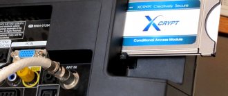
Coaxial digital connection
Perhaps the rarest type of connection in modern audio and video components, coaxial, involves the use of electricity to transmit the audio signal.
The corresponding connector is a familiar round RCA plug that terminates a pair of analog interconnect cables on both sides.
But don't be tempted to use a standard analog RCA cable instead of a dedicated digital coaxial cable! It looks similar and is even quite functional, but its characteristic impedance is lower than that of a digital one (50 and 75 Ohms, respectively), so you won’t get good results. For most systems, an entry-level cable such as QED Performance Coaxial will do just fine.
Today, coaxial connections are less common than optical ones, but they can still be found on the back panels of some AV receivers, amplifiers and televisions.
In our experience, compared to optical, coaxial connections generally provide better sound. It has higher bandwidth, which supports higher quality file formats with up to 24-bit/192 kHz sampling. The optical channel is usually limited to 96 kHz.
The main disadvantage of a coaxial connection is the potential for electrical noise to be carried between devices in the system. It always reduces sound quality and is present to varying degrees in all components. Unfortunately, when using a coaxial connection, noise can be transmitted from the source to the amplifier.
In addition, coaxial cable does not have enough bandwidth to carry high-quality surround sound formats such as Dolby TrueHD, DTS-HD Master Audio, Dolby Atmos and DTS:X. Therefore, the possibilities of its use in a modern home theater system are limited.
Special adapters
To solve problems associated with the placement of cable connections, as well as telecommunications equipment at different levels of modern structures within the framework of compliance with certain standard requirements, special adapters are used - RF connector adapters.
Different sections of modern highways place their own demands on the equipment, therefore, depending on special needs, both professional types of communication outputs and conventional plugs are widely used.
When choosing an antenna connector and a cable for it, in addition to taking into account the above, you should pay attention to the main property of a coaxial cable - a resistance of 75 Ohms, which is indicated on the insulation.
When purchasing a communication cable for independent installation and connection, you should do so with a reserve length, since the necessary preparation for its installation may require more than one attempt, using up a small part of it.
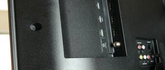
Modern televisions have a number of connectors that differ in purpose to ensure the use of a wide variety of television signal sources. A variety of connectors is necessary to expand the compatibility of equipment of different generations and from different manufacturers.
Today, the technology of using communication connectors is gradually dying out, but due to the demand, some Internet providers and cable TV operators continue to use networks partially based on such devices. The purpose of a coaxial (from the English coaxial) connector for a TV will be described in this article.
Why is there a communication jack on a TV?
The word coaxial, translated from Latin, literally means “shared axis,” and the definition of “coaxial” rather refers to a cable whose device ensures high-quality transmission of a high-frequency television signal from the antenna to the TV. That is, the communication connector is the output from the television receiver for connecting an antenna.
The main purpose of coaxial devices is to provide connections between different types of equipment. This connection has two types of paired components: socket-plug and pin-socket. Each cable corresponds to different types of communication outputs.
According to their functional purpose, the following types of connectors are distinguished:
- instrumentation;
- cable;
- instrumentation and cable.
Due to the high cost of copper structures of main communication cables, they are often replaced by optical analogues. They reduce the cost of production due to partial replacement of copper components. The base is made of steel, partially contains clad copper, and is braided with steel and aluminum wires on top.
Based on the assembly method, there are three groups of cable connectors:
- wound;
- crimping;
- compression
Screw-on connectors
The body of the screw-on coaxial output has a built-in rounded thread and is complemented by a press-on nut.
This type of connection connector is also called a screw-on connector. It is especially widely used at home and is very popular due to the ease of connection, the implementation of which does not require special skills or special tools.
However, such common plugs have a number of significant disadvantages:
- fragility, unreliability of the structure;
- the housing ring is not pressed against the nut to the full extent required, as a result of which the connectors are damaged when screwed in;
- the internal thread is insufficient in length, which makes the maximum tightness of the cable fixation impossible and, as a result, causes interference during signal transmission;
- When the plug is screwed onto the cable, the conductors are gradually partially cut/broken, and the protective covering along with the wire braiding is also twisted as it is used.
Crimp connectors
The crimping device uses two cylinders: an outer one, which seems to continue the structure of the housing, and an inner one, which is selected according to the diameter of the cable dielectric with foil. The circular symmetry of the cable is not broken during shrinkage of the outlet. Its body is pressed into a hexagonal prism using a crimping tool.
The antenna crimp connector also features a simplified mounting method.
The characteristics of such connectors may deteriorate due to the use of low-quality materials for their production, as a result of which they quickly wear out.
Compression connectors
The positive properties of compression coaxial outlets with the complexity of their design fully compensate for their relative high cost. They are considered the most reliable, but connecting to them requires understanding the specifics of fastening and the use of special devices.
The advantages of this type of coaxial connectors include:
- anti-corrosion coating;
- operation up to 3 GHz;
- protection from moisture;
- greatest resistance to mechanical stress;
- better shielding compared to others;
- the highest possible resistance to high and low temperatures;
- high tensile strength.
Balanced output
In the field of professional audio equipment, one of the reference connection options is balanced . Externally, it is not much different from a wide-profile TRS, but its operating algorithm allows you to achieve noticeably better sound quality.
With an unbalanced connection (the usual jack/minijack used in smartphones and inexpensive players), the signal arrives through two conductors: ground and the information channel (left/right). This solution can significantly reduce the final cost of an audio device, but has one drawback - a high level of interference.
With a balanced connection (symmetrical), the signal passes through three conductors: two information channels (direct and reverse) and ground. Thus, the electrical impedance between the conductors is balanced because it is supplied in antiphase. The result: a significant increase in the power of the useful signal and minimization of interference.
How to listen: Shielding the cable against antiphase... The winner will definitely be the balanced connection version. Forget about interference, noise and distortion, but it's still physics.
30-PIN USB CABLE
The 30-pin-to-USB is an Apple® connection cable that provides charging and data syncing for early iPod®, iPhone®, and iPad® models. It features a proprietary plug on one end and a USB Type A plug on the other end. In 2012, the 30-pin cable was replaced with a Lightning™ to USB cable.
What and how is transmitted via S/PDIF?
To guarantee the correct transmission of stereo sound from a CD, it was enough to provide a speed of 150 KB/s, but the developers played it safe and included a reserve for bandwidth. S/PDIF can carry not only the uncompressed stereo signal from a CD, but also multi-channel audio in 5.1 or 7.1 using compression. As well as a certain amount of additional service information, such as the track number, a flag about the permissibility of copying, the presence of compression, and the number of channels. The total information flow can theoretically reach 1.536 Mbit/s. Just one and a half megabits per second - by modern standards this is a ridiculous figure.
It's even more fun to study the protocol from the inside: stereo audio transmission was implemented using PCM pulse code modulation. Data was transmitted in packets of 32 bits each, of which 24 transmitted data, and 8 transmitted service information. If there was less data (some compacts were written in 16 bits), then the rest of the packet was filled with zeros. Not very rational, but effective - the broadcast signal was clocked through service bits, so it could have a very different sampling rate. And although the protocol hardware only supported the transmission of a PCM stereo stream with specific sampling frequencies (32, 44.1 or 48 kHz), they managed to squeeze multi-channel into it.
DVD audio and video media use multi-channel audio in 5.1 or 7.1 format, which is quite successfully compressed according to the Dolby and DTS standard, and transmitted through initially stereo S/PDIF. Yes, it compresses so well that the bit content is even lower than 16 bits. The missing bits are again filled with zeros.
Hardware implementation [edit | edit code]
The S/PDIF specification allows for several types of cable and connectors. Keywords for electric type are "coaxial" and "RCA jack". The other type is called "optical" with the word "TOSLINK" or, less commonly, "EIAJ Optical" often used. There are adapters for switching from coaxial RCA Jack S/PDIF to optical TOSLINK S/PDIF and vice versa, they require an external power source. The advantage of the S/PDIF optical type is its excellent resistance to electrical interference.
S/PDIF remains largely identical at the AES/EBU protocol level, but has different physical connectors that are cheaper and easier to use than XLR.
Types of connectors and cables [edit | edit code]
- Digital signal with TTL levels. TTL - Transistor-transistor logic. TTL usually (but not always) has two levels: >2.4 V (one) and 0-0.4 V (zero). TTL S/PDIF outputs are also available in sound cards.
- Coaxial. A coaxial cable with a characteristic impedance of 75 Ohms, connected to RCA connectors. Regular audio cables (tulips) can be used to transmit an S/PDIF signal over short distances (up to 0.5 m); for longer distances, a 75 ohm coaxial cable must be used. The coaxial cable must be terminated on both sides - the output impedance of the transmitter is 75 Ohms, the input impedance of the receiver is also 75 Ohms (terminators are already built into the devices). Without load, the transmitter output voltage is 1 volt peak-to-peak (p-p), under load it is 0.5 volt p-p. Taking into account losses on a long cable, a minimum voltage at the receiver input of 0.2 volts p-p is allowed.
- TOSLINK - fiber optic cable. Nowadays, MiniTOSLINK connectors have become very popular. Mini toslink is an optical cable connector in the 3.5 jack form factor. Very often such connectors are found in modern laptops, where the S/PDIF output is combined with a headphone output. To connect such a laptop to the receiver, you will need a MiniTOSLINK - TOSLINK cable, or an adapter for a standard TOSLINK-TOSLINK cable.
75 OHMS COAXIAL CABLE
75 ohm coaxial cable is used for high speed data transmission and audio/video signals. The most widely used type of such cable is called RG-6. Typically, coaxial cable is used in television antennas and is used to connect cable and satellite receivers. Bare coaxial cable can be crimped with RCA, F-type or BNC connections using a compression tool.
Special adapters
To solve problems associated with the placement of cable connections, as well as telecommunications equipment at different levels of modern structures within the framework of compliance with certain standard requirements, special adapters are used - RF connector adapters.
Different sections of modern highways place their own demands on the equipment, therefore, depending on special needs, both professional types of communication outputs and conventional plugs are widely used.
When choosing an antenna connector and a cable for it, in addition to taking into account the above, you should pay attention to the main property of a coaxial cable - a resistance of 75 Ohms, which is indicated on the insulation.
When purchasing a communication cable for independent installation and connection, you should do so with a reserve length, since the necessary preparation for its installation may require more than one attempt, using up a small part of it.
Modern TV models are equipped with a large number of connectors that make it easier to use additional signal sources. This is necessary to increase the compatibility of equipment from different manufacturers released at different times. Each connector has its own purpose. That is why it is worth considering them separately.
AM ANTENNA INPUT
Many tuners and receivers use an external antenna to receive AM radio stations. Typically there are two antenna inputs, one labeled AM and the other labeled ground. Most loop antennas have interchangeable bare wires that can be used for any input.
Possibility of repairing connectors at home or in a service center
You can repair the antenna plug on a TV of the brand described above either in a service center or at home. The latter option for providing the service has a number of advantages, among which the following are worth noting:
- quick departure of the technician to the client’s home;
- performing competent diagnostics and repairs;
- saving the client time and effort;
- availability of services in terms of cost.
Regardless of whether the client prefers repairs in a service center or at home, the service will be provided with the highest quality possible.
BI-AMPING
Bi-amping is a speaker wiring method that uses two channels of amplification to power a single speaker. For a two-channel amplifier to operate, each speaker must have two sets of input terminals. This feature is available on some floorstanding and bookshelf speakers.
Bi-amping doubles the power the speaker receives. It can improve audio performance by separately controlling bass and treble frequencies. Bi-amping is an option on receivers that have assignable amplification channels, such as home theater AV receivers. Read more about bi-amping here.
Protocol [edit | edit code]
S/PDIF can be used to transmit digital signals in a variety of formats. The most common of these are the format used in DAT with a sampling rate of 48 kHz and the CD recording format with a sampling rate of 44.1 kHz. In order to support both of these systems, the format does not have a specific data bitrate. Instead, data is transmitted using Biphase Mark Code, which has one or two transitions for each bit of data, allowing the original word clock to be transmitted along with the signal itself.
Extending the capabilities of this interface, S/PDIF can be used to transmit 20-bit audio data streams plus other related information. It is also possible to transmit 16-bit streams with zero padding or 24-bit streams, at the expense of omitting additional information.
The low level protocol is almost the same as in the AES/EBU description. The only difference is the channel status bit.
Channel status bit in S/P-DIF [edit | edit code]
Each sub-frame has one channel status bit, resulting in a 192-bit word in each audio block. This means that there are 192/8 = 24 bytes available in each audio block. The meaning of the channel status bit in S/PDIF is completely different from AES/EBU.
For SPDIF, 192-bit words are divided into 12 words of 16 bits each. The first 6 bits of the first word are the control code; the meaning of these bits is shown in the table:
Meanings of control codes in SPDIF
| Bit number | If not specified: | If specified: |
| User | Professional | |
| 1 | Regular | Compressed data |
| 2 | Copying prohibited | Copying permitted |
| 3 | 2 channels | 4 channels |
| 4 | — | — |
| 5 | No pre-emphasis | With pre-emphasis |
Compression varieties
Relatively expensive products due to their complex design. But the characteristics of such outputs compensate for any expenses at the initial stage of acquisition.
They have the following advantages:
- Anti-corrosion coating.
- Operation up to 3 GHz.
- Additional protection against moisture.
- Shielding is better compared to conventional cables.
- The temperature range is pleasingly wide, from -40 to +70.
- The breaking voltage is higher when compared with cables.
ETHERNET NETWORK CABLE
Ethernet cables are used to connect devices for high-speed network access. Ethernet connection ports are found on computers, smart TVs, game consoles and Internet players. Ethernet cable can be purchased on a reel for arbitrary length runs. RJ-45 connectors and a special tool are used to crimp the connectors. There are also cables with a fixed length, so-called patch cords, which are sold with pre-installed connectors. Ethernet cables are identified by their category (CAT for short). Many versions available. CAT-5e (e for enhanced) and CAT-6 are the most common types used today. Once revolutionary, CAT-5 is almost obsolete in today's fast-paced world. CAT-5 is capable of transmitting speeds up to 100 megabits per second. CAT-5e is ten times faster, with speeds up to 1000 Mbps (Gigabit). CAT-7 wire is by far the most advanced, with speeds up to 10 Gbps.
About special adapters
Switching with already ringed cables is a characteristic feature of modern offices. At different levels there are cable connections and telecommunications equipment. In this regard, problems arise with space for bending structures and compliance with certain standards. RF connector adapters are special adapters, the use of which allows you to solve the problem.
Every outlet on the modern market is created to solve a problem. Inexpensive varieties with simple threaded connections can work normally on individual subscriber telephone lines. But this does not mean that the same equipment will cope with particularly important sections of cable networks. You will need to purchase professional types of connectors, crimp or compression. Each section of the highway has its own requirements for equipment.
S-VIDEO CABLE
S-video cables use a round 4-pin connector used to carry analog video signals. The "S" in S-video stands for "separate". S-video is not used these days, but can be found on older DVD players, VCRs, and televisions.
RP-SMA: why this connector was created, a little history
To comply with certain rules and laws, the RP-SMA connector was created, and the reason is this: previously, the SMA connector was used on wi-fi routers and signal amplifiers began to appear, and as you know, there are certain sanitary standards for signal strength, and so that the standards did not violate, we had to create a connector that is not yet used anywhere. In simple words, so that amplifiers could not be screwed to the routers, since they all had an SMA connector. To spend less effort and time, the specialists decided not to worry and simply swapped the pins in the center of the connector: where there was a pin, they made a hole, and where there was a hole, they made a pin.
Therefore, the term “reverse polarity” does not hide anything like that, but simply means a change in “gender”, that is, a change in pins (signal wires). This term can mislead humanists, and even engineers who have not dealt with Wi-Fi networks, because by the words “change of polarity” many people imagine a change in electromagnetic polarity, when plus changes to minus, but here the pins simply swapped places.
XLR CABLES
XLR cables carry an analog signal between compatible audio components. They are typically used with high quality two-channel systems as well as microphones. The XLR connector has three pins - positive, negative, and ground. The presence of a ground wire makes XLR cables known as "balanced" or "balanced" cables. This helps reduce electronic noise throughout the cable. A latch built into the round XLR plug locks it tightly into the receiving jack for a secure connection.
Types of antenna connectors.
- Authorized ICOM dealer
UHF connector (or PL-259/SO-239)
The most popular type of antenna connector that you will find on most mobile and landline radios is the UHF connector. This is a fairly old design that existed until the 50s of the last century. In those days, everything up to 30 MHz was considered UHF, then this connector system was called UHF i.e. "Microwave connector". This connector is also called PL-259 - MALE (from PIN - “plug”) or SO-239 MAMA (from SOCKET: “socket”).
Despite its popularity, the UHF connector has significant losses at frequencies above 100 MHz. Thus, if you need a high-performance connection for VHF or UHF, you must use other connectors. Diamond
Antenna
calls these connectors MJ (female) and MP (male) .
TYPE N (PLUG, MALE)
The UHF connector disadvantages described above will invariably result in a “Type N” design. Type N is perhaps the most versatile and mechanically reliable of all antenna connector types available today. It was developed in the 1940s for military use and today can be used at frequencies up to 11 GHz. By using a rubber gasket in the housing socket, Type N creates a watertight connection.
Due to its waterproof and mechanical quality characteristics, the Type N connector is most often used in VHF/UHF radio base stations or repeaters.
ICOM RF J (ICOM professional antenna connector)
ICOM's own development for professional wearable radios. Used approximately since the mid-1990s. Provides a highly durable and efficient connection between the antenna and the body of the portable radio station. Female type on the radio and male type on the antenna. To connect cables or mobile antennas, adapters of the RAD-B or RAD-U type are used.
SMA (subminiature version A, MALE, MALE)
SMA is a lightweight, versatile connector that is especially useful for small handheld radios. It can efficiently transmit signals in the range from 0 to 18 GHz (well beyond the VHF and UHF range), using a reliable threaded connection. As with most applications, the SMA was designed to meet military needs, so its small size has excellent strength and low loss. The vast majority of portable antennas have an SMA connector.
SMA socket (or socket, MAMA, FEMALE)
The SMA jack is the same design as SMA, however its use in some portable radios makes it incompatible with most standard antennas (without adapters, of course). With standard SMA the plug is on the antenna, SMA-F - vice versa.
"SMA Female" is a popular connector type in China, used in Baofeng, Leixen and Yanton, for example.
BNC (Bayonet Neal-Konzelmann)
BNC was created in the late 1940s for use in small military radios. Its bayonet connection is its biggest advantage - locking is achieved in just a quarter of a turn. Unfortunately, it is quite large and less mechanically stable compared to its SMA competitor. Perhaps for this reason it has had less popularity in the last few years. Many models of ICOM receivers and radios are produced with this connector, for example IC-A14, IC-A16, IC-R20, IC-R30, etc.
Due to its bayonet shell, BNC can be used at frequencies not exceeding 4 GHz.
TNC (Threaded Neal-Konzelmann Connector)
A TNC connector is exactly the same as a BNC connector, except that it is threaded. Its threaded connection provides greater mechanical strength. Thanks to its threaded contact, it is capable of transmitting signals at much higher frequencies than BNC, up to approximately 11 GHz.