Double triangle antenna.
Based on materials from the book by Yu.G. Sindeev “Television Antennas”
One option for a zigzag antenna is a double triangular antenna, which has small dimensions and fits well with coaxial cable without any additional devices. It consists of triangular frames connected in parallel and located in the same plane. The coaxial cable is laid along the sides of the frame, bringing it to the canvas at one of the points of zero potential, as shown in Figure 1. The main dimensions of the double triangular antenna are calculated using the following formulas:
l =0.27h max a 1 =1.42 l +qb 1 =1.42 l D=0.09 la 2 = a 1 +3D b 2 = b 1 +2D
Rice. 1. Double triangle antenna.
h max is the maximum wavelength of the operating range. The value of q is taken equal to 20 mm in the meter range and approximately 10 mm in the decimeter range. When making an antenna sheet from a tube, the diameter of the latter must be chosen equal to 0.5D. A double triangular antenna, like a zigzag one, is used for television reception in both the decimeter and meter wavelengths, although in the case of the meter wavelength it is quite large. The radiation patterns of a double triangular antenna without a reflector in the vertical and horizontal planes are shown in Fig. 2.
Rice. 2. Radiation patterns of a double triangular antenna.
With the minimum permissible traveling wave coefficient in the cable equal to 0.5, the antenna covers the frequency range of channels 1-5 or 6-12, or 21-39. The calculation results for meter and decimeter range antennas are given in tables 1 and 2. These sizes are the smallest. However, larger antennas can be made, thereby improving cable matching and directional properties. The dimensions are determined using the same formulas, taking a different value of the ratio 1/h (within 0.27. 0.55). It is recommended that the antenna fabric, designed to operate in the frequency range of channels 1-5, be made of wires. Antennas for channels 6-12 can be made from wires, metal tubes or strips, and the UHF antenna can be made from foil fiberglass laminate
Table 1. Dimensions of triangular antennas for the meter range
| Channel numbers | lMM | a1MM | a2MM | b1MM | b2MM | DMM | qMM |
| 1 -5 | 1670 | 2390 | 2840 | 2370 | 2670 | 150 | 20 |
| 2-5 | 1390 | 2000 | 2380 | 1980 | 2230 | 126 | 20 |
| 3-5 | 1060 | 1530 | 1800 | 1510 | 1700 | 96 | 20 |
| 4, 5 | 964 | 1390 | 1650 | 1370 | 1580 | 87 | 20 |
| 5,6 | 880 | 1270 | 1510 | 1250 | 1410 | 80 | 20 |
| 6-12 | 466 | 681 | 807 | 661 | 745 | 42 | 20 |
| 7-12 | 445 | 652 | 772 | 632 | 712 | 40 | 20 |
| 8-12 | 426 | 625 | 740 | 605 | 682 | 38 | 20 |
| 9-12 | 410 | 600 | 710 | 580 | 655 | 37 | 20 |
| 10-12 | 390 | 578 | 684 | 558 | 629 | 35 | 20 |
| 11, 12 | 378 | 558 | 660 | 538 | 606 | 34 | 20 |
| 12 | 365 | 538 | 637 | 518 | 584 | 33 | 20 |
Table 2. Design dimensions of multi-channel double triangular antennas
Source: irls.narod.ru
Simple antennas for digital terrestrial television DVB-T2,
as well as GSM, 3G, 4G and Wi-Fi - DIY antennas.
What Russian doesn't like freebies? Hearing this word, we immediately activate the Muladhara chakras and joyfully fill ourselves with the sacred energy of the Universal Cosmos. Why the hell do we need this free catalog in a beautiful bag from a lingerie manufacturer? And what about the six hundredth gelding in exchange for “fill out the competition participant form and indicate your number (so that we call you and delight you with your victory!)”? These simple thoughts will work in your head sooner or later, but not right away and not for everyone. Yes, and today we will talk about something completely different.
With the advent of the DVB-T2 era, the messenger of God came to the world and said to all seekers: “Brothers, throw away your filthy satellite dishes, and pick up your tinning irons. What you and I once tried to do with a teapot, we can now try to do with any other product!”
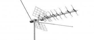
And on this page we will set up a small indoor antenna for receiving the still free digital television DVB-T2 (from the English Digital Video Broadcasting - Second Generation Terrestrial). Yes, such that it matches the medium-sized “wave channel”, widely known in narrow circles as the Yagi-Uda antenna.
I'll start with the good. We will not make the Kharchenko antenna (aka double square, aka BiQuad) ! And it’s not that it’s bad - it’s quite a decent antenna, but it’s just too big for an indoor one, and it’s also been chewed up and down by the powerful jaws of the handicraft people.
And to warm up, let's start with the simplest, but very effective UHF antenna made from coaxial cable, which is easy to make with your own hands, literally in five minutes .
This antenna appears in several credible sources of information. It was noticed both in the book “Antennas for Radio Amateurs”, authored by I. Grigorov, and in the book “HF and VHF Antennas” by I.V. Goncharenko, and, probably, somewhere else, should have also been featured.
Here is what the author of the first source writes about her:
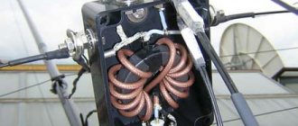
“Magnetic antennas are often used to receive radio broadcast stations, but they can also be used for television reception. The magnetic antenna can be made from any brand of coaxial cable. Such an antenna is inferior in gain to traditional television antennas, but due to the fact that it reacts only to the magnetic component, it provides much better reception quality in urban environments when operating in a wide frequency range. The length of the cable from the antenna to the TV is not critical.”
|
Here we need to slow down for a moment and pay attention to a common mistake made by those who want to participate in the event to implement this design.
Fig.2
The design of the antenna under discussion is the product of transforming a classic magnetic antenna (Fig. 2 a)) with a cut in the middle of the cable braid into a modified one - without a cut (Fig. 2 b)). Moreover, if the first of them requires the presence of a balun transformer for matching with an asymmetrical coaxial cable, then in the second, such matching is not required, it is already inherent in the antenna design itself. What am I getting at? And to the fact that these are two different antennas, and attempts to combine them into one design (antenna sheet with a cut in the cable + matching by shorting the central core to the braid) will result in a surrogate product with the corresponding characteristics.
This loop antenna is capable of working not only for reception, but also for transmission and will perfectly cope with the function of a 3G, 4G or Wi-Fi antenna , when its size is converted to the appropriate range.
A simple calculator for calculating the size of a coaxial cable loop, I think, has never hurt anyone.
Next, we smoothly move on to a more complex UHF receiving antenna. At the same time, in terms of reception range, it may well compete with active indoor antennas from the famous Dutch manufacturer Funke, which is deservedly considered a benchmark in the antenna industry.
The design is based on a double triangular antenna , described in the book by G. I. Boriychuk and V. I. Bulych “For a radio amateur about television antennas”, and then in the magazine Radio No. 6, 1998 (article “Antenna - per hour of work” , under the authorship of V. Mikhailov, with a detailed description of this design for receiving UHF channels).
Fig.3
This antenna is good because, with significantly smaller dimensions, it provides almost the same gain as the Kharchenko antenna - about 5 dB without a reflector. Let's look at excerpts from V. Mikhailov's article.
“The antenna allows you to receive television programs in the UHF range with very good quality, even outside the direct line of sight of the transmitting antenna. The proposed double triangular antenna design can be manufactured quite quickly. The main materials are sheets of corrugated cardboard from packaging boxes, household aluminum foil of suitable sizes, as well as a coaxial cable with polyethylene insulation (not fluoroplastic) and a characteristic impedance of 75 Ohms.
The manufacture of the antenna begins with drawing the contours of its fabric onto sheets of foil and cardboard according to Fig. 3. It is permissible to cut off the sharp corners at the edges a little. Then, carefully cutting out the antenna fabric from a sheet of foil, apply water-based glue (for example, Bustilat, PVA, etc.) to the canvas and cardboard. Aligning them with the applied contour, glue them to each other. Clean the canvas from any glue that has fallen on it, especially in places where cables and electrical connections are laid.
Notes from a programmer
As noted in the post Fldigi and Digital Radio in BPSK31/BPSK63, there are three main ways to increase communication range - using either an amplifier, more efficient modes of communication, or more efficient antennas. This time it was decided to try a different antenna, namely the delta loop. This antenna is quite easy to build and has a gain of 1.17 dB compared to a dipole. Additionally, there are several ways to make a multi-band delta.
Theory
Delta loop, also known as “delta” or “triangle”, belongs to the class of loop antennas. A loop antenna is a circle, square, triangle, trapezoid, diamond, or any other convex shape with a perimeter of about one wavelength. The best option in terms of amplification is a circle. But since building an even circle with a perimeter of 40 or 80 meters is an extremely difficult task, in practice they usually build squares (quad loop) or triangles (delta loop).
Let's consider the following options for squares and triangles in turn, from left to right, from top to bottom (the pictures are borrowed from here):
A bottom-fed square (picture 1) is essentially two curved dipoles placed one above the other. Such a square has a gain of about 1.25 dBd, that is, relative to the dipole. Similar to a single dipole, a square has horizontal polarization. The antenna is directional and radiates perpendicular to the plane in which the square is located. The input impedance of the square is about 117 Ohms, and therefore requires matching with a 50 Ohm cable. If you power the square from the side (picture 2), it will represent two vertical dipoles, and, accordingly, have vertical polarization.
The bottom-fed delta (picture 3) is nothing more than a twisted version of the first antenna. Therefore, the antenna also has horizontal polarization. A delta is easier to build than a square because it only needs one mast. But the gain of such an antenna is slightly less, about 1.17 dBd. Delta has an input impedance of about 106 ohms. The antenna can be powered not only from below, but also from above (picture 4), its properties do not change much from this. An inverted delta (picture 5) also has approximately the same properties.
How to get delta with vertical polarization? To do this, you need to take the feeding location at which the antenna has horizontal polarization, count towards λ/4, and power the antenna at this location (picture 6). It is also possible to feed the antenna into the nearest corner, its properties will not change much.
The illustration shows squares with side λ/4 and regular triangles with side λ/3. However, the antenna can be extended. So in practice, rectangles with a ratio of side lengths from 2:1 to 3:1 are often used. As a rule, loop antennas are placed vertically, but they can also be positioned at an angle to the ground slightly different from straight. Among other things, this allows the height of the mast to be reduced.
Horizontally polarized deltas and squares must be positioned high (height on the order of λ/2) relative to the ground in order to have a small radiation angle. Otherwise, the antenna radiates to the zenith, and with its help radio communications are possible only over short distances. A vertically polarized loop antenna only needs to be raised from the ground a couple of meters (0.05 wavelength), and it is suitable for long-distance radio communications.
So far we have been talking about loop antennas designed for one band. Multi-band loop antennas are built either by nesting one frame into another and combining their feeding points (similar to a fan dipole), or by using an antenna tuner at the feeding point. The latter method is simpler and allows the use of a shortened antenna. The disadvantages of the approach are that a tuner is needed, and it is also not very clear what the polarization will be on the “minor” bands.
Practice
I was inspired by the article One Stealthy Delta [PDF] written by Steve Ford, WB8IMY and published in QST magazine May 2002. "One Stealthy Delta" describes a delta loop with a perimeter of 120 feet (36.6 meters), fed from below and matched by an antenna tuner. It is reported that such an antenna is tuned to all HF bands from 80 to 10 meters, as well as to the 6 meter range, which, unfortunately, is not allowed in Russia. John Reisenauer, KL7JR, in his article An Easy to Install Vertical Loop for 80-6 Meters, confirmed the results obtained by WB8IMY using a similar antenna with a perimeter of 150 feet (45.7 meters). History is silent about why both authors decided to use horizontal polarization at 40 meters.
Having considered the options available to me, I decided to settle on the following:
The antenna is an inverted delta with a perimeter of about 37 meters, fed from one of the upper corners. Matching is carried out using the MFJ-971 antenna tuner. The measured length of the antenna turned out to be a little longer, about 38 meters, since the wires sag under their own weight, and the triangle is not entirely even. The delta was made from a “vole” (wire P-274M), which I had left over after experiments with the “long wire” antenna.
The tuner is located in the house, on the second floor window. The opposite corner is mounted on the mast. The mast is a 10-meter rod, according to the manufacturer, made of carbon / carbon fiber. The upper sections of the rod are too thin and not suitable for use in a mast. After their removal, a mast 6.2 meters high remained. One of the removed sections was secured with reinforced tape at the top of the mast, perpendicular to it. The antenna fabric is threaded into this section. To prevent the mast from collapsing under the influence of wind, its sections were glued together with Moment Universal Classic glue and also secured with reinforced tape. The base of the mast is attached to the fence using the same tape. No guy ropes are used. The lower corner of the antenna is at a height of 1.6 meters from the ground. This corner was tied with a rope to a bush growing nearby.
Note: The mast is allowed to bend a little under the weight of the wire, but not much. The so-called “carbon” used in fishing rods is quite fragile, and it is not worth applying extra force to it.
Such an antenna must have vertical polarization on the 40-meter range. At higher frequency ranges, the polarization will not be very clear. But it is not so important, since most of the antenna will be quite high from the ground compared to the wavelength. The antenna plane runs from north to south. Accordingly, it should radiate to the west and east. In these directions my horizon is quite clear. The north is closed by a house; to the south there are neighboring houses quite close.
My tuner has a built-in 1:4 balun. I tried to set up the antenna both with this balun and without it. It works either way, but with a balun the antenna is tuned much better. I note that the use of a built-in balun does not eliminate the need for an external cut-off choke. Without a choke, of course, everything will also work, but you will get strong interference in the house and a high noise level in the antenna, I checked.
The antenna is well tuned to ranges from 80 to 10 meters. When using the built-in 1:4 balun, the SWR does not exceed 2 on any of the bands, and without it does not exceed 3.
In the "core" 40 meter band there is a clear increase to the west and east. The first QSO at night in SSB mode operating at 100 W was received report 59 from France (2700 km to the west). Kazan (720 km to the east) reports 59+20. Tolyatti (790 km to the east) reports 59+15. Kyiv (750 km to the southwest) gives 59+15 with comments “wow, well, I shouted down everyone.” Germany (2000 km to the west) gives report 59+20. Yekaterinburg (1400 km to the east) says 59. Bosnia and Herzegovina (1900 km), Austria (1800 km), Serbia (1800 km) answer confidently. Previously, on inverted-vee, I regularly received operators living in the south of me (Krasnodar, Stavropol, Astrakhan). Nowadays, radio communication in this direction is quite rare.
The antenna also works well on “minor” bands. On 20 meters in FT8 it is often possible to make a QSO with Japan (7500 km). In PSK31 mode, we managed to make a QSO with operator W4PKU, who lives near Washington (7900 km). To the south in this range, the antenna also somehow works, in particular, Oman responds (4000 km). On 30 and 17 meters in FT8 there were many QSOs with operators from Europe. Of the interesting stations on 17 meters, it was possible to contact the United Arab Emirates (3700 km). At 80 meters at night in SSB, Lithuania, Belarus and Ukraine respond confidently. In this range, reports are up to 59+10.
I have not yet particularly tested the 15, 12 and 10 meter ranges, since there is little activity on them. Most likely, everything is fine on them too.
Conclusion
At the time of this writing, I have been using the described delta for several weeks. The mast is holding. There were no complaints from neighbors. Frankly speaking, some miracle on the level of “connecting with Australia like on Skype” did not happen. But there’s nothing particularly to complain about. It turned out to be just a normal antenna.
This antenna also has one non-obvious, but important for me, plus. The fact is that due to its location in the house there are much fewer cables underfoot. If earlier the RG58 stretched 50 meters to the dipole, now it is only 10 meters from the transceiver to the tuner. Thus, cable losses have become significantly less. In addition, there is now not a single guy wire left in the yard.
Overall, I'm pleased.
Addition: Later I realized several more advantages of this antenna. Firstly, in winter the antenna is covered with snow and ice, and is deformed under their weight. As a result, the input impedance changes noticeably. Thanks to the tuner, it is easy to adapt to these changes. Secondly, delta represents a DC fault. Thanks to this, the antenna does not accumulate static, as dipoles or verticals do.
Addition: Refinement of the antenna is described in the note Impedance matching using LC circuits. You may also be interested in the article A simple antenna for a beginner shortwave operator.
Tags: Antennas, Wireless, Ham Radio.
Double triangle antenna UHF dimensions
Double triangle antenna. Zigzag antenna.
(The antenna can be used to receive digital television)
We found out what the reception range here depends on.
We considered the issue of cable selection here.
We connected the antenna to the TV using the plug here.
We found out what to make the antenna (and vibrator) from here.
We looked at what types of reflectors there are here.
We chose the antenna boom mounting method here.
Antenna assembly. Mounting the antenna elements here.
We looked at the antenna mount here.
Coordination of the vibrator of an industrial UHF antenna is here.
All questions regarding antenna manufacturing and antenna design can be found here.
DIY triangle antenna. Dimensions of a simple triangle antenna.
Zigzag antenna made from available materials.
The antenna (zigzag) triangle consists of 2 frames located one below the other in the same plane. Antenna
triangle (zigzag) fits well with 75 ohm cable without additional devices.
The antenna gain relative to the half-wave vibrator is 4.5 dB.
If you need programs for calculating antennas for analogue and digital television, mobile
The triangle antenna is so simple and “unpretentious” that its small gain is compensated by its simplicity
manufacturing and connection, as well as broadband. The design of the triangle antenna is clear from the figure.
Double triangle antenna diagram.
Rice.
Antenna triangle. Double triangle antenna. Zigzag antenna.
The triangle antenna is a type of zigzag antenna and has all its advantages. Antenna
the triangle consists of two frames, made not in the form of rhombuses, but in the shape of triangles. Triangles
converge at the center of the antenna with their vertices. The antenna shown in the figure has a reflector, which determines its
work only from the forward direction (the reflector protects against interference from behind). Read about reflector designs
The triangle antenna can be made of strip, tubes or thick wire. All manufacturing issues
antennas see here
. The triangle antenna allows the antenna sheet to be attached to the reflector using
metal elements. Of course, the triangles themselves can be made with rounded corners. Sharp corners
depicted conditionally. The antenna sheet (two triangles) can be bent from a single piece of metal.
The cable is connected at points C and E. C -
soldering point for the central core of the cable.
E is
the soldering point for the cable shield.
Lay the triangle antenna cable along the sides of the frame where the screen is connected. More on zigzag antennas
read my article here
.
Antenna
you can install it outside the window or on the balcony, but you must seal all points
soldering: element - nut - terminal to ensure good electrical contact in all weather conditions
The triangle antenna has a gain slightly lower than the full zigzag antenna. Simplicity of the triangle antenna
makes it easy to make at home. The triangle antenna has a fairly wide band of received frequencies.
The design presented in this article is designed to receive UHF television (and digital) channels.
Using materials from my articles here
and
here
, you can experiment and change the size of the frames and
reflectors for receiving signals of various frequency ranges. You can easily replace the triangle antenna with
the antenna is a complete “zigzag”, while maintaining all the advantages of such antennas.
If the screen (or foil) cannot be soldered, then tightly wrap it with copper wire and fix it with soldering. Then
solder these wires.
If you need programs for calculating antennas for analogue and digital television, mobile
How to make any antenna?! All materials on antennas » » » here.
For channel frequencies and wavelength λ, see » » » here.
See a simple zigzag antenna here.
Source: 2x2business.ru
Characteristics of household antennas
To evaluate the efficiency of receiving devices belonging to the “indoor antenna” category, the following indicators are introduced:
- Frequency range of the received signal;
- Directional pattern represented in the form of spatial lobes;
- Receiving device gain;
- Its dimensions.
The relationship between gain and directivity parameters to the source of the processed signal is the most difficult aspect when evaluating various antenna samples. As a rule, they appear as mutually exclusive conditions. Thus, as the amplification characteristics of a particular receiving device improve, its directional pattern narrows and vice versa.
On the one hand, such a limitation can be attributed to the advantages of antennas without an amplifier, since narrowing the direction of the received signal improves their noise immunity (does not allow extraneous and reflected radiation to pass through).
Important! On the other hand, antenna samples with a narrow directional characteristic will require extremely precise tuning to the television signal source.
Moreover, the slightest deviation from the given direction significantly worsens the quality of its reception (see picture below).
Directional pattern
The second most important parameter of household structures (the external delta antenna is also one of them) is the frequency range. Most of the known antennas of this class provide maximum gain in a fairly narrow frequency range, which can be expanded by partially reducing the gain.
- What is an antenna amplifier for a TV and how to choose it?
Since modern television broadcasting is designed for a relatively wide frequency range, a universal indoor antenna must also meet these requirements. In addition, due to the difference in the characteristics of meter and UHF waves, the devices for their reception and processing differ significantly in their design, which especially affects the dimensions.
Modern digital television also uses the decimeter range for signal transmission, within which reliable reception is possible only with direct visibility to the transmitting station equipment. At the same time, at large distances from it, you have to either raise the antenna to a certain height, or take additional measures to increase its gain.
UHF ANTENNA - IN AN HOUR OF OPERATION
V. MIKHAILOV, Moscow
| When making your own UHF antenna, you can use the simple design described here and make do with available materials. |
The relatively good transmission of decimeter radio waves through reinforced concrete building structures makes it possible to receive television programs in this range on a simple indoor antenna and often with very good quality, even outside the direct line of sight of the transmitting antenna. The proposed double triangular antenna design can be manufactured quite quickly. The main materials are sheets of corrugated cardboard from packaging boxes, household aluminum foil of suitable sizes, as well as a coaxial cable with polyethylene insulation (not fluoroplastic) and a characteristic impedance of 75 Ohms.
The manufacture of the antenna begins with drawing the contours of its fabric on sheets of foil and cardboard according to Fig. 1 (sharp corners at the edges can be trimmed a little; this is shown in the figure with dashed lines). Then, carefully cutting out the antenna fabric from a sheet of foil, apply water-based glue (for example, Bustilat, PVA, etc.) to the canvas and cardboard. Aligning them with the applied contour, glue them to each other. Clean the canvas from any glue that has fallen on it, especially in places where cables and electrical connections are laid.
Indoor TV antenna “Rhombus”
This simple, but at the same time, reliable design was one of the most common in the heyday of on-air television broadcasting.
Rice. 1. The simplest homemade Z-antenna, known under the names: “Rhombus”, “Square” and “People’s Zigzag”
As can be seen from the sketch (B Fig. 1), the device is a simplified version of the classic zigzag (Z-design). To increase sensitivity, it is recommended to equip it with capacitive inserts (“1” and “2”), as well as a reflector (“A” in Fig. 1). If the signal level is quite acceptable, this is not necessary.
The material you can use is aluminum, copper, and brass tubes or strips 10-15 mm wide. If you plan to install the structure outdoors, it is better to abandon aluminum, since it is susceptible to corrosion. Capacitive inserts are made of foil, tin or metal mesh. After installation, they are soldered along the circuit.
The cable is laid as shown in the figure, namely: it did not have sharp bends and did not leave the side insert.
UHF antenna with amplifier
In places where a powerful relay tower is not located in relative proximity, you can raise the signal level to an acceptable value using an amplifier. Below is a schematic diagram of a device that can be used with almost any antenna.
Rice. 2. Antenna amplifier circuit for the UHF range
List of elements:
- Resistors: R1 – 150 kOhm; R2 – 1 kOhm; R3 – 680 Ohm; R4 – 75 kOhm.
- Capacitors: C1 – 3.3 pF; C2 – 15 pF; C3 – 6800 pF; C4, C5, C6 – 100 pF.
- Transistors: VT1, VT2 – GT311D (can be replaced with: KT3101, KT3115 and KT3132).
Inductance: L1 - is a frameless coil with a diameter of 4 mm, wound with copper wire Ø 0.8 mm (2.5 turns must be made); L2 and L3 are high-frequency chokes 25 µH and 100 µH, respectively.
If the circuit is assembled correctly, we will get an amplifier with the following characteristics:
- bandwidth from 470 to 790 MHz;
- gain and noise factors – 30 and 3 dB, respectively;
- the value of the output and input resistance of the device corresponds to the RG6 cable – 75 Ohm;
- the device consumes about 12-14 mA.
Let's pay attention to the method of power supply; it is carried out directly through the cable.
This amplifier can work with the simplest designs made from improvised means.
Connection procedure
UHF antenna
To understand how to properly connect Delta to a television receiver, please note that this procedure is practically no different from connecting any other device of a similar purpose.
In order to connect it correctly, you first need to cut the mating end of the cable wire for a contact connector or soldering. This operation is necessary in order to arrange it in the form of a standard plug connector, which will be used to connect to the input jack of the receiver.
If a model with a built-in amplifier is used, its design must include another wire designed to connect the delta antenna to the power supply adapter (see the figure below).
Connection diagram
Important! When connecting a cable to a plug, under no circumstances should a short circuit be allowed between the screen braid and the thin central core.
When carrying out the described procedures, it is recommended to follow the instructions for designing television connectors, which should contain a connection diagram.
Indoor antenna made from beer cans
Despite the unusual design, it is quite functional, since it is a classic dipole, especially since the dimensions of a standard can are perfectly suitable for the arms of a decimeter range vibrator. If the device is installed in a room, then in this case it is not even necessary to coordinate with the cable, provided that it is not longer than two meters.
Indoor antenna design based on beer cans
Designations:
- A - two cans with a volume of 500 mg (if you take tin and not aluminum, you can solder the cable instead of using self-tapping screws).
- B – places where the cable shielding is attached.
- C – central vein.
- D – place of attachment of the central core
- E – cable coming from the TV.
The arms of this exotic dipole must be mounted on a holder made of any insulating material. As such, you can use improvised things, for example, a plastic clothes hanger, a mop bar or a piece of wooden beam of appropriate size. The distance between the shoulders is from 1 to 8 cm (selected empirically).
The main advantages of the design are fast production (10 - 20 minutes) and quite acceptable picture quality, provided there is sufficient signal power.
Making an antenna from copper wire
There is a design that is much simpler than the previous version, which only requires a piece of copper wire. We are talking about a narrow band loop antenna. This solution has undoubted advantages, since in addition to its main purpose, the device plays the role of a selective filter that reduces interference, which allows you to confidently receive a signal.
Fig.4. A simple UHF loop antenna for receiving digital TV
For this design, you need to calculate the length of the loop; to do this, you need to find out the frequency of the “digit” for your region. For example, in St. Petersburg it is broadcast on 586 and 666 MHz. The calculation formula will be as follows: LR = 300/f, where LR is the length of the loop (the result is presented in meters), and f is the average frequency range, for St. Petersburg this value will be 626 (the sum of 586 and 666 divided by 2). Now we calculate LR, 300/626 = 0.48, which means the length of the loop should be 48 centimeters.
If you take a thick RG-6 cable with braided foil, it can be used instead of copper wire to make a loop.
Now let's tell you how the structure is assembled:
- A piece of copper wire (or RG6 cable) with a length equal to LR is measured and cut.
- A loop of suitable diameter is folded, after which a cable leading to the receiver is soldered to its ends. If RG6 is used instead of copper wire, then the insulation from its ends is first removed, approximately 1-1.5 cm (the central core does not need to be cleaned, it is not involved in the process).
- The loop is installed on the stand.
- The F connector (plug) is screwed onto the cable to the receiver.
Note that despite the simplicity of the design, it is most effective for receiving “digits”, provided that the calculations are carried out correctly.
Introduction
All wireless data transmission is based on the process of propagation of an electromagnetic field from a source into the surrounding space. The antenna plays the role of this field source. The radiation process itself begins with the fact that, under the influence of high-frequency electromagnetic fields, extraneous currents and charges appear in the radiating system (antenna). Currents and charges, in turn, are supplied from the generator along the feeder path (or feeder from the word “to feed” - to feed).
Thus, the electromagnetic field radiation system includes: an oscillation generator, a feeder and an emitter. Of course, the feeder and generator themselves do not directly participate in radiation (or more precisely, they should not participate if they are properly designed), Figure 1.
Figure 1 – Elements of the electromagnetic field radiation system
Any antenna has the so-called “duality” principle, which says that any antenna can be both transmitting (that is, converting the waves of the transmission line into diverging waves of the surrounding space) and receiving (carry out the inverse conversion).
Regardless of the implementation and type of antenna, it is characterized by the following basic parameters:
Directional pattern (DP). This distribution of field strength (or energy) in space shows in which directions and with what power the antenna system radiates. This dependence is constructed, as a rule, in a spherical coordinate system. Depending on the type of diagram (on how “sharp” the diagram is), there are isotropic antennas, weakly directional, and highly directional. The type of radiation pattern determines such important characteristics of the antenna as the directivity coefficient (DA) and the gain factor (GA). Below we will look at the type of radiation pattern, as well as the directivity and gain of one of the simplest antennas in different planes.
Antenna efficiency. It should be high enough and losses should be small; it is for this reason that when implementing antennas, metal structures with high conductivity and dielectrics with low losses are used.
Matching the transmission line with the load. Since both the transmitting and receiving antennas are connected to the power line, its input impedance must be matched with the characteristic impedance of the line. Otherwise, the unwanted occurrence of reflected waves will occur, and the presence of the latter always means a decrease in the radiated power and a source of additional interference.
Weight and dimensions. It is clear that when implementing any device, one must strive to obtain its smallest weight and dimensions; however, we note that the dimensions of the antenna are uniquely related to the main wavelength at which the antenna operates. In general, in antenna technology there is no concept of “large” and “small” antenna. Antenna dimensions are usually characterized in wavelengths. If a is the diameter of the mirror (for example, a mirror antenna), then its size can be written as follows: this means that 8 wavelengths fit into the diameter of the mirror. If such a mirror operates in the 2.4 GHz range (wavelength 12.5 cm), then its diameter will be 1 meter, and if it is in the 900 MHz range (wavelength 33 cm), then its diameter will be more than 2.5 meters.
Do-it-yourself MV and UHF indoor antenna
If, in addition to UHF, there is a desire to receive MF, you can assemble a simple multiwave oven, its drawing with dimensions is presented below.
Indoor multiwave (MV and UHF) antenna
To amplify the signal, this design uses a ready-made SWA 9 unit; if you have problems purchasing it, you can use a home-made device, the diagram of which was shown above (see Fig. 2).
It is important to maintain the angle between the petals; going beyond the specified range significantly affects the quality of the “picture”.
Despite the fact that such a device is much simpler than a log-periodic design with a wave channel, it nevertheless shows good results if the signal is of sufficient power.
DIY figure eight antenna for digital TV
Let's consider another common design option for receiving “digits”. It is based on the classic scheme for the UHF range, which, because of its shape, is called “Figure Eight” or “Zigzag”.
Rice. 6. Sketch and implementation of the digital eight
Design dimensions:
- outer sides of the diamond (A) – 140 mm;
- internal sides (B) – 130 mm;
- distance to the reflector (C) – from 110 to 130 mm;
- width (D) – 300 mm;
- the pitch between the rods (E) is from 8 to 25 mm.
The cable connection location is at points 1 and 2. The material requirements are the same as for the “Rhombus” design, which was described at the beginning of the article.
Features of operation
Long-term operation of Delta type antennas in the open air requires careful sealing of the input and connection areas of the cable and wire. If there are no traces of treatment with protective agents on the product, you must perform this operation yourself (taking into account the capabilities of this model).
Moisture getting inside the amplifier circuit or on the contact connections can lead to failure of the entire structure, and the cable connected to it can become completely wet in conditions of high humidity. Possible consequences of these operational violations are a short circuit in the power circuits and complete burnout of the entire electronic part of the device.
Additional Information. The only correct way out of this situation is to completely replace the soaked cable along with the antenna plug.
Drying a wet cable product is unacceptable, since over time it will still fail due to the presence of internal elements damaged by corrosion (braided shielding, in particular).
In the event of a noticeable deterioration in the quality of reception on all or several television channels (or its complete loss), you should disassemble the plug and make sure that the wiring of the central core and braid are in good condition. If serious violations are detected, it is necessary to cut off the cable near the damaged connector and make a new contact connection in the form of an antenna plug.
In conclusion, we note that to independently assemble a Delta-type antenna, you need an appropriate level of training and skills to work with devices of this class. There is not enough professional data for this on the Internet, since all the information presented in the sections on this topic concerns mainly amateur radio samples.
Homemade antenna for DBT T2
Actually, all of the examples listed above are capable of receiving DBT T2, but for variety we will present a sketch of another design, popularly called “Butterfly”.
Decimeter antenna "Butterfly"
The material can be used as plates made of copper, brass, aluminum or duralumin. If the structure is planned to be installed outdoors, then the last two options are not suitable.