Antenna matching and matching devices
In amateur practice, it is extremely rare to use antennas whose input impedance is equal to the wave impedance of the feeder, and in turn, the output impedance of the transmitter (ideal matching option). Most often, there is no such correspondence and special matching devices have to be used. The antenna, feeder and transmitter output should be considered as a single system in which energy must be transmitted without loss.
The implementation of this difficult task will require coordination in two places: at the point of connection of the antenna with the feeder and the feeder with the transmitter output. The most popular are various types of transforming devices: from resonant oscillatory circuits to coaxial transformers in the form of sections of coaxial cable of the required length. All of them are needed to match resistances, which ultimately leads to minimizing losses in the transmission line. And, most importantly, to reduce out-of-band emissions.
As a rule, the standard output impedance of modern broadband transmitters (transceivers) is 500m. Most coaxial cables used as feeders also have a standard impedance value of 50 or 750 m. Antennas, depending on the type and design, can have an input impedance in a very wide range of values: from several Ohms to hundreds of Ohms and more. It is known that the input impedance of single-element antennas at the resonant frequency is practically active. And the more the transmitter frequency differs from the resonant* frequency of the antenna in one direction or another, the more a reactive component of a capacitive or inductive nature appears in the input impedance of the antenna. In multi-element antennas, the input impedance at the resonant frequency is complex, since passive elements contribute to the formation of the reactive component.
In the case when the input impedance of the antenna is purely active, it is not difficult to match it with the feeder impedance using any of the suitable transforming devices. At the same time, the losses are quite insignificant. But, as soon as a reactive component is formed in the input resistance, the matching becomes more complicated, and a more complex matching device is required that can compensate for the unwanted reactivity. And this device must be located at the antenna feed point. Uncompensated reactance worsens the SWR in the feeder and increases losses. An attempt to fully compensate for reactivity at the lower end of the feeder (at the transmitter) is unsuccessful, since it is limited by the parameters of the feeder itself. Tuning the transmitter frequency within narrow sections of the amateur bands does not lead to the appearance of a significant reactive component, so in most cases there is no need to compensate for reactance. Properly designed multi-element antennas also do not have much input reactance and usually do not need to compensate for it.
On the air, disputes often arise about the role and purpose of the antenna matching device (antenna tuner) when matching the transmitter with the antenna. Some have high hopes for it, others consider it an unnecessary toy. What actually (in practice) can and cannot help an antenna tuner?
First of all, a tuner is a high-frequency impedance transformer that can, if necessary, compensate for reactance of a capacitive or inductive nature.
Let's consider a simple example: A split vibrator (dipole), which has an active input impedance of about 700 m at the resonant frequency, is connected by a 75-ohm coaxial cable (feeder) to a transmitter whose output impedance is 500 m. The tuner is installed at the output of the transmitter and in this case acts as a matching unit between the feeder and the transmitter, which it easily copes with. If the transmitter is tuned to a frequency different from the resonant frequency of the antenna, then reactivity will arise in the input impedance of the antenna, which will immediately appear at the lower end of the feeder. The tuner is also able to compensate for it, and the transmitter will again be matched to the antenna feeder.
What will happen at the output of the feeder, at the point of its connection to the antenna? Using a tuner only at the transmitter output, full compensation will not be possible, and losses will occur in the feeder due to inaccurate matching with the antenna. In this case, you will need another tuner, which will have to be connected between the feeder and the antenna, then it will correct the situation and compensate for the reactivity. In this example, the feeder acts as a matched transmission line of arbitrary length.
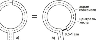
Another example: A loop antenna having an input impedance of approximately 1100 m must be matched to a 50 ohm transmission line. Transmitter output 500m. Here you will need a matching device installed at the point where the feeder is connected to the antenna. Typically, many hobbyists use various types of RF transformers with ferrite cores, but it is more convenient to make a quarter-wave coaxial transformer from a 75-ohm cable. The length of the cable section is A/4 x 0.66, where R is the wavelength, 0.66 is the shortening factor for most known coaxial cables. A coaxial transformer is connected between the antenna input and the 50 ohm feeder. If it is rolled into a coil with a diameter of 15...20 cm, then it will also serve as a balancing device. The feeder and transmitter are automatically matched when their resistances are equal. In this case, you can refuse the services of an antenna tuner altogether.
For this example, another matching method is possible: Using a half-wave or half-wave coaxial cable with any characteristic impedance (also taking into account the shortening factor). It is connected between the antenna and the tuner located near the transmitter. The antenna input impedance of about 110 Ohms is transferred to the lower end of the cable and, using the tuner, is transformed into a resistance of 500 m. In this case, there is complete coordination of the antenna with the transmitter, and the feeder acts as a repeater.
In more complex cases, when the input impedance of the antenna does not match the characteristic impedance of the feeder, and the impedance of the feeder does not match the output impedance of the transmitter, two matching devices are needed. One at the top for matching the antenna with the feeder, the other at the bottom for matching the feeder with the transmitter. And it is not possible to get by with just one antenna feeder to coordinate the entire chain: antenna - feeder - transmitter.
The presence of reactivity further complicates the situation. The antenna tuner in this case will significantly improve the matching of the transmitter with the feeder, thereby facilitating the operation of the final stage, but nothing more. Due to mismatch between the feeder and the antenna, losses will occur, and the efficiency of the antenna itself will be reduced. The switched on SWR meter between the transmitter and the tuner will record SWR=1, but this will not happen between the tuner and the feeder due to the mismatch between the feeder and the antenna.
A completely fair conclusion arises: the tuner is useful in that it supports the normal mode of the transmitter when operating on an unmatched load, but at the same time it is not able to improve the efficiency of the antenna when it is mismatched with the feeder.
The P-circuit used in the output stage of the transmitter can also serve as an antenna tuner, but subject to prompt changes in inductance and both capacitances. As a rule, antenna tuners, both manual and automatic, are resonant loop tunable devices. Manual ones have two or three regulating elements and are not efficient in operation. Automatic ones are expensive, and for high-power operation they are very expensive.
Let's look at a fairly simple broadband matching device (tuner) in Fig. 1, which satisfies most variations in matching the transmitter to the antenna. :
It is very effective when working with antennas (loops, dipoles) used on harmonics when the feeder is a half-wave repeater. In this case, the input impedance of the antenna is different on different bands, but with the help of a matching device it is easily matched to the transmitter. The proposed tuner can operate at transmitter powers up to 1.5 kW in the frequency band from 1.5 to 30 MHz. The main elements of the tuner are an RF autotransformer on a ferrite ring from the deflection system of the UNT-35 TV and a 17-position switch. It is possible to use conical rings from TVs UNT-47/59 or others.
The winding contains 12 turns wound into two wires. The beginning of one winding is connected to the end of the other. In the table and diagram the numbering of turns is continuous. The wire itself is stranded with fluoroplastic insulation. Wire diameter 2.5mm insulation. Taps are made from each turn, starting from the eighth from the grounded end.
The switch is ceramic, biscuit type with 17 positions.
The autotransformer is located as close as possible to the switch, and the connecting conductors between them must be of a minimum length. It is possible to use a switch with 11 positions while maintaining the design of the transformer with fewer taps, for example, from 10 to 20 turns. But in this case, the resistance transformation interval will also decrease.
Knowing the input impedance of the antenna, you can use such a transformer to match the antenna with a 50 or 750 m feeder, making only the necessary taps. In this case, it is placed in a moisture-proof box, filled with paraffin and installed at the antenna feed point.
Also, this matching device can be made as an independent structure or be part of the antenna-switching unit of the radio station.
For clarity, the mark on the switch handle (on the front panel) indicates the resistance value corresponding to this position. To compensate for the reactive component of an inductive nature, it is possible to connect a variable capacitor C1, Fig. 2.
The dependence of the resistance on the number of turns is given in Table 1. The calculation was made based on the resistance ratio, which is a quadratic function of the number of turns.
Table 1.
RELATED ARTICLES ON THE TOPIC:
- Multiband Inverted L Antenna “Inverted L” antenna made from antenna cable. To increase operating efficiency, it is advisable to place its vertical part as high as possible. Such an antenna receives electromagnetic radiation with both vertical and horizontal polarization, so when working on it, the fading that accompanies HF reception should apparently appear less than...
- Antennas. Urban Designs The book discusses antennas that radio amateurs can install in urban environments. Practical antenna designs are presented for all amateur radio HF bands, the MF band of 27 MHz and for the VHF band of 144 MHz, and the method for setting them up is described. Theoretical information is given to the minimum extent necessary for the construction of the described antennas. Book…
- Antennas and their configuration Many do not understand the importance of good coordination of the Radio-Transmission Line-Antenna path. Or rather, they understand the importance, but are completely unable to really assess the state of affairs. Most often, they are content with readings of the built-in SWR meter close to unity. The most unpleasant thing about this is that if the situation is bad, the owner...
- Simple antennas for the 160 m range A simple and effective antenna for the 160 m range is the dream of almost every radio amateur, especially an inveterate “DX hunter”. How can you start working in this range without large technical and material costs? After all, the 160 m range places increased demands on both the skills of a radio amateur on the air,...
- 50 MHz Antenna A simple directional antenna for the 50 MHz band was designed by Robert Snary, G40BE. This type of antenna was proposed for the first time by VK2ABQ for the HF ranges of 14, 21 and 28 MHz due to their greater broadband compared to “squares” and “Yagi”….
- Matching antenna transformer 1:4 (balun) from DGOSA The balun is made on a ferrite toroidal core FT140-43 (ferrite rings 400-600NN with a size of about 35.55 × 23.0 × 12.7 mm can be used). On both halves of this core, two windings of 12 turns are wound with a symmetrical LFL line with a characteristic impedance of 100 Ohms...
- Effective CB band antenna A vertical antenna of 5/8 wavelength plus a quarter-wave cable connected in parallel produces a very simple and effective stationary antenna system for long-distance radio communications on the 27 MHz band….
- Multi-band attic antenna from MM0YEC In distant Scotland, among the hills and moors, there is a small town of Fife, where radio amateur Christoph Echtermeyer, MMOYEC, lives. His radio station is located in a cozy cottage, which is so pleasant in the autumn storm, and in the harsh winter it is well warmed by a fireplace and a glass of good old malt whiskey. Primordial...
Reflection coefficient
Considering how important impedance matching is in RF design, we should not be surprised to find that there is a specific parameter used to express the quality of this matching. It is called the reflectance and is symbolized by the letter Γ (Greek capital letter gamma). It is the ratio of the complex amplitude of the reflected wave to the complex amplitude of the incident wave. However, the relationship between the incident and reflected waves is determined by the source (Zi) and load (Zn) impedances, and thus the reflection coefficient can be determined using these impedances:
\[\Gamma = {Z_n - Z_i \over Z_n + Z_i}\]
If the "source" is a transmission line, we can replace Zi with Z0.
\[\Gamma = {Z_н - Z_0 \over Z_н + Z_0}\]
In a typical system, the reflection coefficient is a number between zero and one. Let's look at three mathematically simple situations that will help us understand how the reflectance corresponds to the actual behavior of the circuit:
- If the matching is perfect (Zn = Z0), the numerator is zero, and therefore the reflection coefficient is zero. This makes sense because with perfect matching there are no reflections.
- If the load impedance is infinite (i.e. open circuit), the reflection coefficient becomes equal to infinity divided by infinity, which is equal to one. A reflection coefficient equal to unity corresponds to total reflection, i.e. all the wave energy will be reflected. This makes sense because a transmission line connected to an open circuit corresponds to complete discontinuity (see previous article) - the load cannot absorb any energy, so it must be reflected.
- If the load impedance is zero (i.e. short circuit), the value of the reflection coefficient becomes equal to Z0 divided by Z0. Thus we again have |Γ| = 1, which makes sense, since a short circuit also corresponds to a complete inhomogeneity, which cannot absorb the energy of the incident wave.
Summary
- Using standardized impedance makes RF design much more practical and efficient.
- Most RF systems are built around a 50 ohm impedance. Some systems use 75 ohms, this value is more suitable for high speed digital signals.
- The quality of impedance matching can be expressed mathematically using the reflection coefficient (Γ). Perfect matching corresponds to Γ = 0, and complete inhomogeneity (in which all energy is reflected) corresponds to Γ = 1.
- Another way to quantify impedance matching is the voltage standing wave ratio (VSWR).
Original article:
- The 50 Ω Question: Impedance Matching in RF Design
VSWR
Another parameter used to describe impedance matching is the voltage standing wave ratio (VSWR or simply VSWR). It is determined by the following formula:
\[VSWR = { 1 + |\Gamma| \over 1 — |\Gamma|}\]
VSWR approaches impedance matching in terms of the resulting standing wave. It expresses the ratio of the largest standing wave amplitude to the smallest standing wave amplitude. The following diagram shows the amplitude characteristics of a standing wave for three different reflection coefficients.
Greater impedance mismatch results in a larger difference between the highest and lowest amplitude locations along the standing wave.
VSWR is sometimes expressed as a ratio. Ideal matching is 1:1, which means that the peak amplitude of the signal is always the same (i.e. there is no standing wave). A ratio of 2:1 indicates that the reflections resulted in a standing wave with a maximum amplitude twice its minimum amplitude.