DIY digital satellite finder.
This article describes a satellite finder that we can build ourselves to help align our satellite dish without taking our receiver outside. We offer a signal strength meter that will greatly help in accurately optimizing the antenna's antenna position once the satellite has been found.
Figure 1: Implementation of satellite search.
Browse products for inventors. The sale has started! from 11.11.21 Link to the store.
The use of satellite retrieval is illustrated in Figure 1. The low noise block (LNB) downconverter used for satellite reception (digital or analog) does not simply receive one channel; it receives the full range from all transponders operating on a particular satellite. Along with high gain, a modern LNB delivers a lot of RF energy to the receiver when the dish is properly aligned. Our digital satellite finder measures the amount of RF energy over a wide frequency range by summing the power of all transponders and producing a Received Signal Strength Indicator (RSSI) output via a proportional DC voltage for display. Since most existing satellite finders only use an analog scale, and some of the satellite finders are partially digital (digital processing with analog display), and the rarely available digital satellite finders are expensive,
RF detector
We use the LTC 5508 IC from Linear Technology to measure RF power. The LTC5508 operates with input power levels from –32 dBm to 12 dBm. This IC is an RF power detector for RF applications operating in the 300 MHz to 7 GHz range. A temperature-compensated Schottky diode peak detector and buffer amplifier are combined into a small SC70 package to detect RF power via a DC voltage output. The detected voltage is buffered and applied to the VOUT pin. Maximum RF power produces a peak output voltage, as shown in Figure 3. A low logic level on SHDN (pin 1) turns off the circuit, and a high logic level turns the circuit on. This is done using the SPST switch (SW1) and resistor R2. The SHDN pin has an internal 150k ohm pull-down resistor to ensure that the part is disabled when no input is being applied. This IC can operate from a supply voltage of 2.7 to 6 V. VCC is supplied to pin 4 and capacitor C3 is used as a bypass capacitor. The coupling capacitor C2 is used to connect the RF signal source to the IC. The frequency range is from 300 MHz to 7 GHz. This pin has an internal Schottky diode detector and a peak detection capacitor. The LTC5508 application diagram is shown in Figure 2.
LTC 5508 Application
Figure 2. LTC 5508 Application Diagram The LTC5508 RF detector includes several features that provide RF power detection at frequencies from 300 MHz to 7 GHz. These features include an internally compensated buffer amplifier, an RF Schottky diode peak detector and level shift amplifier to convert the input RF signal to DC, a delay circuit to avoid voltage transients at VOUT when coming out of shutdown, and a gain compression circuit for expansion dynamic range of the detector. The buffer amplifier has a gain of two and can withstand a load of 2 mA. The buffer amplifier typically has an output voltage range of 0.25 to 1.75 V. electronicsforu.com Digital Satellite Finder An internal RF Schottky diode peak detector and level shift amplifier convert the input RF signal to a low frequency signal. The detector exhibits excellent efficiency and linearity over a wide input power range. The LTC5508 can be used as a stand-alone receiver for signal strength measurements, and depending on the specific needs of the application, the RSSI output can be divided into two branches, providing AC-coupled data output and DC-coupled output, RSSI output for signal strength measurements and AGC The following graph (Figure 3) shows the proportional DC output voltage for the corresponding RF input signal. This is connected to the digital voltmeter through R1 and C1.
DIY electronics in a Chinese store.
Figure 3. LTC5508 PV characteristics
Application of cyclic capacitors
Devices with cyclic capacitors have been used to tune antennas for a very long time. A wide variety of receivers are suitable for them. To assemble the model yourself, first of all you should select the body. After this, a modulator is installed directly to adjust the threshold frequency of the device.
The next step is to fix the capacitors on the chip using a blowtorch. Next, all that remains is to buy chromatic resistors. In this case, it is advisable to use a pulse type converter. Many experts recommend using magnetic filters. The average sensitivity of the device should be at the level of 3 microns by default. Such devices are ideal for shortwave systems.
Power supply
The integrated power supply is supplied using two series voltage regulator ICs (LM1086-ADJ) as shown in Figure 4. The required supply voltages are obtained from the satellite receiver itself using the same RF cable. The 10 mH inductor (L1) acts as an RF choke to prevent the DC RF signal from drifting to the satellite finder. The voltage regulators are designed using LM1086 IC to provide 5V and 3.6V respectively.
The 5V power supply is used for the digital display and the 3.6V power supply is used for the RF power detector. The LM1086 regulated version develops 1.25V reference voltage, (VREF), between the output terminal (PIN2) and the setting terminal (pin1), at 1.5A load current. Two resistors are required to set the output voltage of the LM1086 variable output voltage version. Fixed output voltage versions include control resistors.
Load regulation is 0.1% (typical) and line regulation is 0.015%. The component count of the device is very minimal, using two resistors as part of the voltage divider circuit and an output capacitor for load regulation. The voltage divider for this part is set based on the equations shown below; where R3 / R5 is the upper feedback resistor. R4 / R6 - lower feedback resistor. VOUT = 1.25 V (1 + R6 / R5) for 5 V output VOUT = 1.25 V (1 + R3 / R4) for 3.6 V output where R3 / R5 is the upper feedback resistor. R4 / R6 - lower feedback resistor. VOUT = 1.25 V (1 + R6 / R5) for 5 V output VOUT = 1.25 V (1 + R3 / R4) for 3.6 V output where R3 / R5 is the upper feedback resistor. R4 / R6 - lower feedback resistor. VOUT = 1.25 V (1 + R6 / R5) for 5 V output VOUT = 1.25 V (1 + R3 / R4) for 3.6 V output
Figure 4. Power Supply If the output capacitor is large (≥100 µF) and the input is momentarily shorted to ground, the regulator may be damaged. In this case, an external diode (D1) between the output and input contacts is recommended to protect the regulator. Capacitors C4 and C6 are used as output filters for both regulators. The pinout diagram of the LM1086 chip is shown below (Figure 5).
Figure 5. Top view of IC1086
Using pulse converters
Devices with pulse converters are quite in demand today. They are suitable for tuning selective type antennas. Receivers are most often selected for devices of the optical type. In this case, the assembly of the model must begin with the installation of pass-through capacitors with a display. In this case, the regulator can only be taken of the rotary type.
To stabilize the signal transmission process, only chromatic resistors are used. In this case, zener diodes are used quite rarely. A total of two thyristors are required for the device. One of them should be installed directly at the converter. In this case, the second thyristor is mounted near the modulator.
Digital voltmeter
An accurate digital voltmeter using IC L7107 from Intersil Corporation, used for digital display. The application diagram is shown in Figure 6. The ICs include a low power, 3.5 analog digit digital converter, internal circuitry for seven segment decoders, display drivers, a voltage reference, and a clock. The power dissipation is less than 10mW and the display stability is very high.
The working of this electronic circuit is very simple. The measured voltage is converted to a digital equivalent by the ADC inside the IC, and this digital equivalent is then decoded into a seven-segment format and then displayed. The ADC used in the L7107 chip is a dual-loop ADC. The process occurring inside our ADC can be formulated as follows. Over a fixed period of time, the measured voltage is integrated to produce a linear change in the output of the integrator. Then a known reference voltage of opposite polarity is applied to the input of the integrator and allowed to increase until the integrator output becomes zero.
Input voltage comparison and conversion
The time required to reach a negative zero slope is measured in the IC clock cycle and will be proportional to the voltage being measured. Simply put, the input voltage is compared to an internal reference voltage and the result is converted into a digital format. 14.2 mm (0.56 inch) seven-segment LED displays are available as a common anode (DISP1 - DISP4). Resistors R13 and C13 are used to set the frequency of the internal clock of the chip. Capacitor C12 neutralizes fluctuations in the internal reference voltage and improves display stability. A 0.1uF capacitor gives good results in most cases. Resistor R10 controls the range of the voltmeter. On the right, most of the three displays are connected so that they can show all the numbers. The leftmost display is connected in such a way that it can only display “1” and “-”. Pin 5 (representing the point) is connected to ground for the second display only, and its position must be changed when changing the range of the voltmeter by changing R10. (R10 = 1.2K gives 0-20V range, R10 = 12K gives 0-200V range).
Digital voltmeter using L7107 chip
Rice.
6. Digital voltmeter circuit using the L7107 chip. Analog input required to generate full scale (2000 counts): VlN = 2VREF. Thus, for a scale of 200 mV and 2 V, the VREF value should be 100 mV and 1 V, respectively. This is done by resistors R7, R8 and R9. The integrating resistor must be large enough to remain in this very linear region over the entire input voltage range. Therefore we use R12 = 470K in our circuit. The integrating capacitor must be selected to give maximum voltage swing and the nominal value is 0.22 µF (C11).
The size of the automatic zero capacitor (C10) has some effect on system noise. On the 2V scale, a 0.047uF capacitor increases the speed of recovery from overload and is suitable for noise on this scale. The display is 3 1/2 digits, meaning the 1999 maximum display rate with a decimal point is included if desired. The decimal point is connected through resistor R14 to ground. There is also no need to use four displays; You can use just 3 to display 999 or 100mV, 1V, 10V, 100V range. The ICL7107 is designed to operate from ±5V power supplies. However, if a negative power supply is not available, it can be generated from the clock output (pin 38 on IC2) with 2 diodes (D3 and D4), 2 capacitors (C14 and C15) and a low-cost CD4049 IC (IC3) as shown in the following figure7.
Figure 7. Negative supply generation.
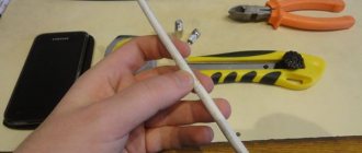
Antenna tuning device
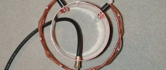
This article proposes a device for measuring the resonant frequency of antennas with cable feeders. It does not allow one to obtain any fundamentally new results, but is easier to manufacture and use. For example, the reflectometer from K. Rothhammel’s book “Antennas” requires a power supply of several tens of watts to the measuring line, and even more in the low frequency ranges, otherwise the reflected wave in the measuring line will be very small in amplitude and insufficient for its linear detection by a diode. As a result, the device will show excellent SWR even with a decent mismatch. Is this where the frequent statements on the air come from, that one or the other has built their antennas very well at 1.8 MHz and the SWR is equal to one? If you do not increase the length of the measuring line by three times compared to that indicated in the book by K. Rothhammel, then at 1.8 MHz even a power of half a kilowatt is barely enough for the incident wave to deflect the instrument needle to the end of the scale. There can be no question of a linear measurement of the reflected wave. Its signal simply will not open the diode. Measuring SWR at 1.8 MHz at permitted powers of 5 and 10 W with simple reflectometers seems completely unrealistic.
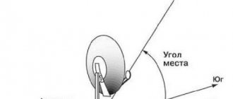
The proposed method is not associated with the registration of the reflected wave and does not require any power, which, in addition to the obvious convenience during setup, will reduce the range load. The method is based on the influence of the antenna on the oscillating circuit to which the antenna is connected. It is known that the input impedance of the feeder is purely active and is equal to the characteristic impedance of the cable only in the case of perfect matching, i.e. if it is loaded with an active resistance equal to the wave resistance, and there is no reactive component. When there is a frequency mismatch, either an inductive or a capacitive component appears in the input resistance. If the feeder is connected in parallel to an oscillating circuit, the inductive component will cause the frequency to move up, and the capacitive component will cause the frequency to move down. Moreover, the deviation must be compared in relation to the position that exists when connected to the active resistance circuit in the form of a resistor equal in value to the characteristic impedance of the cable. To measure the resonant frequency of the circuit, it is convenient to include it in a tunable self-oscillator, the frequency of which is recorded by an external frequency meter (Fig. 1). The connection between the antenna and the circuit must be weak, otherwise the generation will break down or be very unstable. Much attention should be paid to switch S1, which must have minimal parasitic inductance and capacitance; The lengths of the installation wires from S1 to the equivalent resistor and antenna socket should be kept to a minimum. When choosing a power source, you must keep in mind that the amplitude of the generated voltage on the circuit must be large enough. Otherwise, during measurements, external powerful signals received by the antenna will delay the frequency of the generator and measurements will either not be obtained at all or will be inaccurate.
Operating procedure
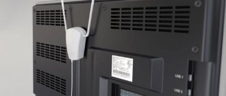
The installer can simultaneously view the azimuth and vertical degree projection of incoming signals, as well as measure and tune the antenna for azimuth and viewing angle. Satellite signals can be visualized and any obstacles can be avoided. Site & Satellite Finder can be located below the antenna dish, the compass will give correct readings for MAGNETIC as well as NON-MAGNETIC satellite dish. You must know (at your location) the declination-corrected azimuth (magnetic north) and elevation angle for each satellite you want to receive signals from. Disconnect the coaxial cable coming from your receiver to the LNB (at the end of the LNB), then connect the signal meter to the LNB using the length of the coaxial cable (1 to 3 meters). The receiver can also be connected to a signal meter. Since the device can be connected symmetrically, you can connect the device in any direction. Requires power from the receiver, so leave the receiver turned on. But there is no need to set it for a specific channel.
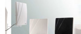
Semi-professional and amateur
Semi-professional “tweeters” - a budget solution - are represented by devices with a mechanical signal indicator. The mechanics are sensitive to the influence of radio waves, so the accuracy of adjustment with devices of this model may not be ideal.
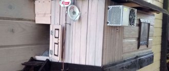
When you search for “homemade device for setting up satellite dishes,” the Internet will give you links to amateur devices, constructed mainly from a small TV and a receiver. But there are also devices based on individual circuits and personal software.
If you prefer this option due to its low cost, then you need to know that the quality of tuning with such a device is questionable. In addition, any homemade device, and especially a tandem of a portable TV and tuner (even if they are compact), will not provide you with the required pace of work where mobility is necessary.
Schematic diagram of satellite search
Rice. 9. Complete circuit diagram of a digital satellite finder. Point the dish in the approximate direction of the desired satellite using a compass or the sun's shadow at a given time. Use your favorite tracking program to determine the compass direction or time the Sun will reach the same direction (azimuth) as the satellite. To increase the satellite's signal gain, smoothly change the satellite's azimuth and elevation to maximize the meter reading. The digital display will show 2.5-2.8V for better reception. Remember that being off-directional by just 5° could mean you get nothing, or worse, you may have optimized on a nearby satellite! Once you have found the best plate alignment, you can optimize the position of the LNB in the feed clamp. Try rotating the LNB slightly from its normal position and moving it towards or away from the dish to get maximum reading. Always check the reception on the receiver to make sure you optimized on the correct satellite before you fix the dish! If you are using a motorized polar mount, you can also use a satellite meter on the receiver side.
Low sensitivity modifications
If satellite TV is connected, the antenna can be adjusted using a low-sensitivity model. Today it is quite common. However, it has very significant disadvantages. First of all, they are associated with poor stabilization of models. They use only optical receivers.
In this case, the sensitivity on average does not exceed 2 microns. All this is due to the fact that filters in this case are suitable only for the magnetic type. However, the main advantage of the models is the quick adjustment of low-frequency zener diodes. Thus, signal pairing occurs quite quickly. For beginners, such devices are ideal.
Experimental design
(This is the circuit implemented and tested first (Figure 8), for which I have attached a prototype for your verification. The readings are observed using a digital multimeter. Tested antenna for AIRTEL TV)
Rice. 8. Experimental Satellite Search Circuit Although this circuit consumes a very small amount of RF from the LNB, it may degrade the performance of your system, so remove it after antenna alignment is completed. It is important that the wires shown thick on the schematic diagram are as short as possible (less than 5mm) as we are dealing with high frequencies here. Solder these parts directly to the back of the F connector. Use a short coaxial cable to connect both F connectors to each other inside the box. Finally, the finished unit must be placed in a metal box to prevent RF leakage. The complete circuit diagram of the proposed digital satellite finder is shown in Figure 8. The circuit diagram made for the experimental setup is shown in Figure 9. The PCB layout and component layout for this experimental circuit are shown in Figures 10 and 11 respectively. We hope this digital satellite finder will be a more useful tool for installing and maintaining satellite TV connections.
PCB Layout -
Solder side component layout (Layouts are the wrong size)
electronicsforu.com
Connection options
The user has two ways to configure the dish to receive broadcasts:
- Specialist services. You can call a master and just wait a little while he does all the work, but you will need to pay a lot of money for it.
- Self-installation. In this case, the user saves money, but it will take a lot of time and effort to find the exact direction for the antenna.
The second option is more attractive, but first you need to consider how the setup process works.