ANTENNA,
a structure used to transmit or receive radio waves (i.e., electromagnetic radiation with wavelengths ranging from ~20,000 m to ~1 mm).
Examples of the use of antennas include radio and television broadcasting, long-distance radio communications on short waves and microwaves reflected by satellite antennas, radar - all these physical processes and technical systems are based on the transfer of energy in the form of electromagnetic waves through air and outer space. The function of a transmitting antenna is to convert the electromagnetic energy coming from the transmitter into an emitted electromagnetic wave. On the receiving side, it is also necessary to have an antenna that receives part of the energy emitted by the transmitting antenna and sends it to more or less complex detecting and amplifying circuits, which form the basis of the receiver. Cm
.
RADIO AND TELEVISION; RADAR. Also on topic:
RADIO AND TELEVISION
ANTENNA TYPES
The type of antenna design depends on the wavelength at which it must operate. To effectively radiate energy, the antenna must have dimensions close to the operating wavelength. Therefore, at the low frequencies used at one time for transatlantic radiotelegraph and radiotelephone communications (frequencies from 16 to 70 kHz, i.e. waves with a length of 19 to 4.3 km), a huge system of antenna wires with a total length of up to 2 km was electrically short antenna and therefore turned out to be an ineffective radiator. If such an antenna was supposed to have a noticeable directionality, then its efficiency would be very low. On the contrary, at ultrahigh frequencies (microwaves), the use of a half-wave symmetrical vibrator less than 1 cm long and a polished metal reflector with a diameter of only a few centimeters makes it possible to very effectively focus the radiation of such a vibrator into a narrow beam.
Wireless radio waves
When the need for wireless communication arises, an antenna is needed. It has the ability to send or receive electromagnetic waves for communication where a wired system cannot be installed.
The antenna is the key element of this wireless technology. Radio waves are easily created and are widely used for both indoor and outdoor communications due to their ability to pass through buildings and travel long distances.
Key features of transmitting antennas:
- Since radio transmission is omnidirectional, there is no need for physical matching between the transmitter and receiver.
- The frequency of radio waves determines many transmission characteristics.
- At low frequencies, waves can easily pass through obstacles. However, their power decreases with the inverse square of distance.
- Higher frequency waves are more likely to be absorbed and reflected by obstacles. Due to the long transmission range of radio waves, interference between transmissions is a problem.
- In the VLF, LF and MF bands, the propagation of waves, also called ground waves, follows the curvature of the Earth.
- The maximum transmission ranges of these waves are on the order of several hundred kilometers.
- Transmit antennas are used for low-bandwidth transmissions such as amplitude modulation (AM) radio transmission.
- HF and VHF transmissions are absorbed by the atmosphere close to the Earth's surface. However, part of the radiation, called the sky wave, travels outward and upward to the ionosphere in the upper atmosphere. The ionosphere contains ionized particles formed by radiation from the Sun. These ionized particles reflect sky waves back to Earth.
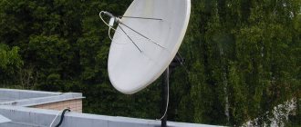
Quarter-wave transmitting antenna mast.
Also on topic:
ELECTROMAGNETIC RADIATION
The main coverage area of a broadcast station is "served" by surface (ground) wave. In order for a wave to propagate near the earth's surface, it must have vertical polarization, i.e. the radiation electric field vector must be vertical, and hence a vertical antenna is required. In reality, it is sufficient to have only a half-height antenna; the reason for this is its mirror charge.
When an electromagnetic field encounters a conducting plane on its path, it is specularly reflected from it. Therefore, the electromagnetic field created above a conducting plane by a certain system of currents and charges turns out to be identical to the field that would exist if instead of a conducting plane there was a mirror-reflected system of currents and charges, i.e. simply a mirror image of the real system in a given plane. Thus, the field above the plane is the field of a vertical half-wave symmetrical vibrator (Fig. 1). Such a vibrator radiates most intensely in a plane perpendicular to its axis; in the case under consideration, this means that the radiation is directed along the earth's surface. In practice, such an antenna is a steel mast with a height of about a quarter of the wavelength, mounted on support insulators (Fig. 2). The earth is made a good conductor by burying a system of wires in it, diverging in radial directions from the base of the antenna. If the antenna mast is equipped with guy wires for stability, then they must be divided into sections with insulators that are short enough so that the influence of the guy wires on the local field of the antenna is insignificant.
Compound blocks
There are certain rules in our Universe. People discovered this thousands of years ago when they began to distinguish between the force of gravity and the ability of some objects to attract or repel other objects. Then people discovered another set of rules of attraction and repulsion that were completely separate from the first.
People have categorized objects and determined through experimentation that positive and negative are opposite manifestations of a property called charge, just as north and south poles are opposite manifestations of something called magnetism, just as left and right hands are two types hands
Image showing mirror symmetry between electric charges, magnetic poles, and hands
Something happened in Oersted's wire regardless of whether the compass needle was under it or not. This leads to the idea of intangible electromagnetic fields that permeate the Universe - both the densest matter and the vacuum. Each of our objects, categorized as (+/-/N/S), affects the space around it and is affected if the field surrounding it changes.
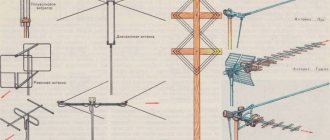
Directional antenna arrays made from antenna masts.
There are two reasons why a broadcast station might require a directional radiation pattern. Firstly, its “audience” may be located mainly on one side of the location of the transmitting station. So, for example, a regional station located in a coastal city must create a stronger signal in the continental direction if it is undesirable for half of its power to be lost to the sea. Secondly, it may be necessary to avoid mutual interference in the area served by any remote station operating on the same frequency; in this case, the radiation pattern of a given station should have zero radiation in the direction to the distant one.
Radiation directivity is often achieved by creating an array of two or more antenna masts, in which the distances between the masts and the excitation phases of the antennas of each mast are selected to obtain the desired radiation pattern. Let's illustrate this approach with an example. Let there be two identical antenna masts, located at a distance of half a wavelength from each other and excited by currents of the same magnitude and phase. The radiation of each antenna is equally directed in the horizontal plane; Thus, when viewed from above, each of the antennas appears as a point source of circular waves propagating uniformly in all directions. The radiation pattern of such a two-antenna array is determined by the superposition of the waves emitted by both antennas. As shown in Fig. 3, points located on the west-east (WE) axis are half a wavelength farther from one antenna mast than from the other. Thus, at these points the two emitted waves are 180° out of phase and therefore cancel each other out; As a result, there is no radiation along the WE line in both directions. Points located on the straight north-south (NS), on the contrary, are at the same distance from the antenna masts, so that both waves at these points are in the same phase and are summed. Such a system is called a side (transverse) radiation antenna array - its radiation pattern is shown in Fig. 4, a
.
If the antenna masts radiate in antiphase (phase difference 180°), then mutual cancellation of waves will occur along the NS axis, and their addition will occur along the WE axis. Such a system is called a longitudinal (axial) radiation antenna array. Its radiation pattern is similar to that of the transverse radiation grating, but rotated by 90° (Fig. 4, b
).
If two antenna masts are located at a distance of a quarter wavelength from each other and are excited by currents of equal magnitude, but the wave emitted by the eastern mast is 90° ahead of the western one in phase, then the radiation pattern will have a cardioid shape (Fig. 5, dotted line) . The dashed and solid lines in the figure represent the radiation patterns obtained when the eastern mast is advanced in phase by 45° and 180°, respectively.
Broadcast receiving antennas.
Broadcast receiving antennas with a height close to half or even a quarter wavelength tend to be prohibitively large. Fortunately, this limitation is often not significant, since the field strength generated by the transmitting station is usually so high that even a small antenna will provide more than sufficient signal for a modern radio receiver. Excluding extremely remote locations from consideration, it must be said that a long outdoor antenna does not improve the signal-to-noise ratio and can often only worsen reception. Most broadcast radios come with a built-in loop or ferrite antenna. Such a device is an electrically small magnetic dipole.
If the electric and magnetic lines of force that form the antenna's field are reversed, the resulting field is theoretically possible in the sense that it obeys the laws of electromagnetism. The difficulty is that emission of such a field requires a magnetic analogue of the original radiating system; but the magnetic analogue of electric charges moving along electrical conductors is some magnetic charges moving along magnetic conductors; however, neither a magnetic charge nor a magnetic conductor has yet been discovered. There is, however, a magnetic analogue of a very small dipole - an inductor. Although the miniature magnetic dipole, or loop antenna as it is called, is a very inefficient transmitting antenna, its small size and excellent ability to withstand local interference and noise make it an ideal means for receiving radio broadcasts. The radiation pattern of a small loop antenna is shown in Fig. 6. By rotating the frame, you can, using clearly defined zeros of the diagram that coincide with the axis of the frame, eliminate the reception of interference. Such a loop antenna can be in the form of a flat spiral wound coil placed on the rear wall of the receiver housing, or in the form of a thin solenoid with a ferrite core. Due to the sharply defined zeros of the radiation pattern, such a loop antenna is used in direction-finding equipment.
The FM broadcast band (88 to 108 MHz) is sandwiched between the lower and upper channels of the VHF television band (channels 2 to 13); Therefore, the antennas used for transmitting and receiving FM signals are essentially the same as those used for television, and although the following description will deal primarily with television antennas, the latter are more or less suitable for FM broadcasting as well. Typically, both FM radio stations and television broadcast stations transmit on horizontally polarized waves.
Television transmitting antennas.
A television (or FM) transmitting antenna is typically required to produce uniformly distributed (non-directional) radiation in the horizontal plane; however, in the vertical plane it is advantageous to concentrate the radiation into a relatively narrow beam directed towards the horizon, because this is where the “audience” of viewers and listeners being served is located. Energy directed above or below the horizon is either lost into space or goes into the ground. The characteristics of the radiation pattern in the vertical plane of a particular television transmitting antenna can be determined by comparison with the corresponding pattern of a horizontal half-wave symmetrical vibrator in the vertical plane containing this vibrator. The antenna power gain is defined as the ratio of the input power supplied to the symmetrical vibrator selected for comparison to the power supplied to the input of the antenna, the gain of which must be determined, provided that both antennas give the same radiation intensity in the horizontal plane at a distance of one mile (1.6 km). Effective radiated power is defined as the power in watts carried through the connecting line (feeder) from the transmitter to the antenna, multiplied by the antenna gain. Thus, the effective radiated power is typically much greater than the actual transmitter power.
One of the antenna design problems that is especially important for television broadcasting is eliminating reflections from the antenna back into the connecting line. This reflected energy is reflected by the transmitter into the antenna, where it arrives with a delay equal to the quotient of the double length of the feeder divided by the speed of light, and leads to the transmission of a delayed echo signal to the antenna. In the worst case, this echo can appear on the received picture as a secondary image (a faint reproduced image shifted to the right), but even in less unpleasant consequences, the clarity of the resulting image deteriorates.
The problem of reflections, like other problems associated with antenna design, when transmitting a television signal is aggravated by the requirements for path bandwidth. The video information of a television signal occupies a band of about five megahertz, which is almost 10% of the carrier frequency of the lower channels of the TV range. This means that the television transmitting antenna must be designed to meet stringent requirements not only on one frequency, but also over a wide frequency band. A half-wave symmetrical wire vibrator would be completely unsuitable for television transmissions, since even if it is coordinated with the feeder and there are no reflections at any one frequency, then when the frequency changes by 5%, the dipole will reflect a quarter of the energy supplied to its input into the feeder.
The television transmitting antenna used in practice is a “turnstile” model, which consists of two crossed horizontal symmetrical vibrators made of pipes with a diameter of 5 or 8 cm. Each vibrator has a directional pattern in the horizontal plane in the shape of the figure 8, and when two vibrators are excited with a 90° phase shift, the resulting diagram in the same plane becomes almost omnidirectional. Directivity in the vertical plane (and therefore the antenna gain) can be improved by installing several tiers of turnstile antennas on the antenna mast, one above the other.
The turnstile antenna is a prototype of one of the most widely used television transmission antennas, called the “super turnstile”. The vibrators of a simple turnstile antenna took the form of emitters with a butterfly configuration - this configuration makes it possible to obtain a much larger broadcast bandwidth. The power gain of a three-tier super turnstile antenna is about 4.
Transfer of information
Probably the two most well-known methods of transmitting information are frequency modulation (FM) and amplitude modulation (AM).
Frequency modulation
With frequency modulation, information is transmitted by changing the frequency of the carrier wave.
Frequency modulation
Amplitude modulation
With amplitude modulation, the frequency of the carrier wave remains constant. Information is transmitted by changing the amplitude of the carrier.
Amplitude modulation
Television receiving antennas.
Unlike the waves used for AM broadcasting, the waves used for TV broadcasting are much shorter, so half-wavelength receiving antennas are feasible. Thus, a television half-wave symmetrical vibrator is so small that it can be made from a rigid tube. However, the small size of even an electrically long antenna at these frequencies means that the effective reception area of the incident wave (and therefore the antenna's ability to capture its energy) is limited. Additionally, due to the large bandwidth of the television signal and the noise distributed evenly across the channel, the receiver must receive a significant amount of power to provide an acceptable signal-to-noise ratio. In light of the above, it becomes clear that the efficiency of the antenna plays an important role in the reception of a television signal.
At operating frequencies of television broadcasting, atmospheric interference is not of particular importance, but the receiving antenna will pick up a lot of industrial interference and cosmic noise. Therefore, it is important that the receiving antenna has a clearly defined directionality, which allows it not to receive signals coming from directions that do not coincide with the direction of the desired transmitting station. Another type of interference that often degrades the quality of television reception is multipath propagation, in which the desired signal arrives at the receiving antenna along two paths of different lengths. So, for example, one signal can come directly from the transmitter, and another can be reflected from a mountain or building. Multipath propagation appears on the screen in the form of multi-contour images, and to get rid of it, you need to use a directional antenna that allows you to exclude reception along one of the two beams.
The bandwidth of a television receiving antenna must be very large, since it is required to cover not just one channel, but usually all thirteen, located in the 4:1 frequency range. Fortunately, matching the transmission line to the antenna, in which reflections do not occur, is not so important on the receiving side, where the mismatch only leads to the loss of a weak signal without generating echoes. However, the matching of the connecting line to the receiver is important, but in this case attention should be paid to the design of the receiver.
Reflections arising from irregularities in the connecting line can cause multi-edge or loss of image sharpness. These reflections often occur if a two-wire ribbon cable runs too close to metal structures, such as wire trays or drains. This will become clear if we remember that high-frequency electromagnetic energy propagates in a field that arises around the wires that serve as conductors of this field.
One of the simplest antennas used to receive a television signal is the half-wave loop dipole (Fig. 7), which differs from the conventional half-wave dipole in that its output impedance (300 ohms) is consistent with commonly used types of feeders, as well as the that it has a wider band; in other words, it effectively transfers the received electromagnetic energy of a wider range of frequencies into the connecting line.
To obtain the desired radiation pattern in the horizontal and vertical planes, the base antenna is usually used in conjunction with one or more passive elements. A passive element is another antenna located close to the main one, but not connected to the feeder. It is connected to the main antenna (and therefore to the receiver) only by local fields. Understanding how a passive element affects an antenna's radiation pattern is easy because it uses essentially the same principle as an omnidirectional array antenna; the difference is that in this case only one antenna is excited, while the other receives energy only from its near field. As an example, we note that a half-wavelength rod placed (as shown in the figure at a distance of a quarter wavelength from a half-wave dipole) acts as a reflector. Why this is true can be explained as follows. The local field of the excited (main) antenna induces passive element, the charges and currents are of the opposite sign, but due to the distance of a quarter wavelength, these currents and charges lag behind the corresponding currents and charges in the main antenna by approximately a quarter of a period, i.e. the current in the passive element leads the current in the main antenna by approximately 90° The radiation pattern of the driven antenna with a passive element is determined by superimposing both radiated wave fields. This situation is very similar to that considered for an omnidirectional (in the horizontal plane) AM broadcast array, its radiation pattern is shown by the dotted line in Fig. 5. These two waves tend to cancel each other in the direction of the passive element and reinforce each other in the opposite direction; hence the passive element acts as a reflector. The passive element does not have to be a quarter wavelength away from the antenna being excited. If it is placed very close to it, for example at a distance of only 0.1 wavelength, it will still act as a reflector if its length is made slightly more than half the wavelength. Increasing the length of the passive element makes it inductive, as a result of which the current flowing through it lags in phase with the electromotive force induced by the field of the main antenna. If a nearby passive element is made slightly shorter than half the wavelength, it becomes a guide (“director”) and concentrates the radiation on its side of the main antenna. All of the above is directly related to receiving antennas. Since the transmitting and receiving radiation patterns are the same, passive directors and reflectors can be used in television receiving antennas to obtain the required radiation pattern. A typical highly directional antenna array with one reflector and three directors is shown in Fig. 9.
Wave Propagation
- Line of sight propagation. Among all the distribution methods, this is the most common. The wave travels the minimum distance that can be seen with the naked eye. Next, you need to use an amplifier transmitter to increase the signal and transmit it again. Such propagation will not be smooth if there is any obstacle in its transmission path. This transmission is used for infrared or microwave transmissions.
- Ground wave propagation from a transmitting antenna. The wave propagates to the ground along the contour of the Earth. Such a wave is called a direct wave. The wave sometimes bends due to the Earth's magnetic field and hits the receiver. Such a wave can be called a reflected wave.
- A wave propagating through the earth's atmosphere is known as a terrestrial wave. The direct wave and the reflected wave together produce a signal at the receiving station. When the wave reaches the receiver, the delay stops. Additionally, the signal is filtered to avoid distortion and amplification for clear output. The waves are transmitted from one place and where they are received by many transceiver antennas.