Repairing a TV power supply is one of the most difficult tasks for an electronics technician. If you understand how power supplies or switching power supplies work, it will be easier for you to troubleshoot any problems in other types of circuits such as color, vertical, audio, high voltage, etc.
How does TV power work? What are the main user mistakes that lead to failure of the power supply? Why do TVs suddenly stop turning on? Let's figure it out.
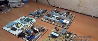
Manifestation of PSU malfunction
Unlike other TV components, any failure of the power supply immediately affects the performance of the TV as a whole. This means that after turning on the TV to the network, the activity indicator will not even light up, not to mention the output of sound, pictures or other signs of life. The breakdown may be as follows:
- the TV does not turn on and the LED does not light up;
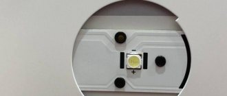
- the device does not function due to protection in the power supply, which is usually accompanied by a whistling noise from the pulse transformer. This manifestation may also indicate the necessary repair of the LED backlight in the TV;
- The output voltage is too low or too high from the power supply.
If the device can turn on and simply exhibits some kind of defect in its operation, then this is most likely caused by another component of the TV, and not the power supply. However, there are also a number of exceptions in which the problem is still associated with the power supply:
- the device does not turn on, although the standby LED is on;
- the image appears some time after the sound;
- To get a normal picture and sound, the TV must be turned on and off several times.
Separately, it is also worth mentioning possible breakdowns of other components of the TV, which are not caused by problems with the power supply, but directly affect its operation. These include power supply units, feedback circuits, power supply loads, and so on.
Main reasons
Failure of the power supply is one of the most common breakdowns of modern LED TVs. The cause of this malfunction can be caused by many factors, but among them there are 4 main ones:
- Unstable voltage. If the voltage in the outlet constantly “jumps”, then it can not only worsen the performance of the TV, but also lead to wear and tear of its components.
- Short circuit. Causes burnout of the power supply or other components of the TV.
- Burnt out mains fuse. In this case, the standby indicator will not light up.
- Capacitors wear out over time. A very common problem that does not depend on external factors. Worn capacitors can be identified by their swelling.
Prices for repairing a TV power supply
| Service | Price, rub. |
| Primary circuit repair | 2000-3000 |
| Secondary circuit repair | 2500-3500 |
| Repairing inverters or backlight drivers | 3500 |
| PFC repair | 3000 |
Visitors to the page also read the following articles on repairs:
- Samsung TV PSU Repair
- Diagnostics and repair of TV Daewoo power supply
- TV Supra power supply repair
- Printer power supply repair
Algorithm for finding a breakdown and repairing it
Repairing televisions and other household and industrial equipment can be profitable and cost-effective, but only if you have a minimum of technical literacy and are familiar with all relevant safety precautions. Not every amateur can repair a power supply. This is a very difficult and unsafe activity.
But if you still feel confident and want to understand the reasons why your TV is not working, in particular, check its power supply, we will suggest you perform the following sequence of actions:
- Unplug the TV and check the socket itself: the problem may be an unstable network voltage or a malfunction of the socket itself (or extension cord).
- Discharge the high-voltage capacitor on the board so that there is no short circuit in the future (you can simply short-circuit it with an insulating screwdriver, a tester, or hold a light bulb to it for a couple of seconds).
- If everything is fine with the power supply in the system, then the next step is to dial the standby power supply, in which, as was written earlier, the voltage should be maintained at 5 volts. If less, you will need to check the capacitors.
- Now check the fuse - often due to a temporary overload or due to a short circuit in the mains voltage circuits, this part may simply burn out.
- Now remove the TV case and remove the motherboard.
The actual cause of fuse failure can be power surges, sudden shutdowns, lightning strikes or random power failure. Important! You can only replace a blown fuse with a part of the same rating recommended by the manufacturer of the electronic device!
After this, place the board on a flat surface and conduct a visual inspection:
- Check the board itself for ring cracks;
- Using a special voltage measuring device (tester), check each resistor, transistor, electrolytic capacitor, diode;
- Carefully inspect all soldering areas, the continuity of etched tracks, whether there are breakdowns, breaks, etc.
If you notice a darkened or cracked resistor, it will need to be replaced. The resistance of these elements with values in the range from 0 to ∞ is also a sign of their inoperability. If there are capacitors on the board with a swollen top cover, they will also have to be replaced.
The operation of silicon diodes can be checked in two ways:
- Unsolder the board and check the voltage with a tester (in mode with a limit of 20 kOhm): in the forward direction the value should be 3-6 kOhm, in the reverse direction – ∞;
- The soldered diodes are checked with a multimeter in the voltage drop measurement mode - the value should be up to 0.7 V (if the voltage is 0 or close to that, then the element will still have to be unsoldered and checked using the first method).
Bipolar transistors need to be checked twice: both in the forward and reverse directions.
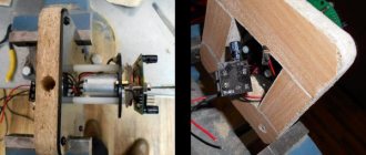
To check the supply voltage of a switching power supply, do the following:
- Take a circuit and 2 100-watt light bulbs.
- Determine where the horizontal scan output stage is located.
- Unplug it and plug in a light bulb instead.
- Find the power filter capacitor in the secondary circuits and connect a second light bulb to it, which will create a load simulation.
If the light comes on, this indicates that there are problems in the power supply: in the input circuits, rectifier, network, power capacitor, etc. But if the light comes on, goes out, and then lights up very poorly, then the power supply is normal. And the diagram will be needed in order to determine exactly where the gap formed.
If the power is turned off and the fuse has not blown, then most likely there is a faulty starting circuit (open starting resistors), open fusible resistors (due to short semiconductors), faulty controller components.
Diagnosing problems in switching power supplies is sometimes complicated by the interdependence of components that must function properly in order for any part of the power supply to perform its part of the operating process.
Depending on the design, an SMPS may or may not be overload protected: one model may fail catastrophically under heavy load, even if there is a short circuit protection fuse. In another power supply, communication devices (often 800 V transistors) may fail.
In addition, such equipment may malfunction when power is restored after a power outage. This moment is very tense: any power surge is undesirable. (Some designs take this into account and limit the turn-on jump).
However, the cause of many problems is immediately obvious and has simple fixes - the weakest link in their composition is a blown transistor chopper or a dry main filter capacitor. Don't assume that all power supply issues will always be complicated and confusing. In most cases no.
Features of repair work and tools for them
For a standard type of device, the above stages of diagnostics and repair work will be identical. This is due to the fact that they all have a typical structure.
Read also: How to connect a digital receiver for a TV
Soldering parts to the board
Also, in order to carry out high-quality independent repairs of a pulse voltage converter, you need a good soldering iron, as well as the ability to operate it. In this case, you will also need solder, alcohol, which can be replaced with purified gasoline, and flux. In addition to a soldering iron, the following tools will definitely be needed for repairs:
- Screwdriver Set;
- tweezers;
- household multimeter or voltmeter;
- incandescent lamp. Can be used as ballast load.
With such a set of tools, anyone can do simple repairs.
How to check for serviceability in practice?
In general, external diagnostics of possible malfunctions and breakdowns of the power supply is as follows.
If the appearance of the capacitors causes you any suspicion, then they must be immediately removed and replaced.
If you notice interruptions in the operation of the standby mode, you need to immediately check the voltage on the controlled zener diode. If there is no voltage at the output of this node or it is too low, therefore, the operating mode is disrupted.
In order to restore the functionality of the element, it is necessary to verify the functionality of all other parts of the circuit. To do this, you should unsolder one contact of the suspicious capacitor or resistor, remove all burnt elements completely and immediately replace them with new ones. If you see an area of poor-quality soldering, this area needs to be tinned with flux, and then make sure that the contacts are firmly fixed in the fastening area.
The restoration of the power supply circuit and the return to standby mode will be indicated by the appearance of a voltage of 5 V, as well as the blinking of the red light indicator on the front panel of the TV.
Please note that whenever you replace other suspicious elements, you must immediately check whether changes have occurred at the output of the power supply.
The fact that the functionality of the equipment has been returned can be judged by the TV turning on normally and the receipt of high-quality audio and video.
Carrying out repair work
When planning to repair a damaged pulse voltage converter with your own hands, you need to understand that such manipulations are not carried out for products intended for complex replacement. They are not designed for repair and no technician will undertake to repair them, since it requires complete dismantling of the electronic filling and replacing it with a new working one.
Switching power supply board
In all other cases, repairs at home and with your own hands are quite possible. Proper diagnosis is half the repair. Faults associated with the high-voltage part can be easily detected both visually and using a voltmeter. But a fuse malfunction can be detected if there is no voltage in the area after it. If faults are detected with its help, all that remains is to simply replace them simultaneously. When carrying out repair work, it is necessary to rely on the appearance of the electronic board. Sometimes, in order to check each part, it is necessary to unsolder it and test it with a multimeter. It is advisable to check all details. Despite the difficulty of such a process, it will allow us to identify all damaged elements of the electrical circuit and replace them in time to prevent burnouts of the device in the foreseeable future.
Replacing burnt out parts
After all the burnt out parts have been replaced, you need to install a new fuse and check the repaired power supply by turning it on. Usually, if everything was done correctly, and all standards and instructions for repair work were followed, the converter will work.
How to connect?
Let's take a closer look at how to connect the power supply. In most cases, the amplifier is already built into the active antenna. But in passive it is not there. To connect it, you first need to assemble an antenna cable with a plug that will be intended for these purposes. Let's look at how to do this.
First you should prepare the cable itself, that is, strip it. To do this, use a sharp utility knife or scalpel to make a thin incision around the circumference at a distance of 1.5 cm from the edge of the cable. When performing this work, it is very important to be careful and try not to damage the hairs of the shielded braid located immediately under the insulating layer.
After these steps are completed, the mentioned hairs must be carefully bent back and the piece of foil located near them must be removed.
Stepping back approximately 5 mm from the folded edge of the braid, you need to make another cut around the circumference. It is necessary to remove the inner insulating layer. After this, the cable, prepared for installation, should be inserted under the appropriate fasteners in the power supply box and tightened with screws.
We pay special attention to the fact that when a wire is connected, its metallized braid must have contact with a tinned pad, which is a mandatory design element of any power supply housing. If this is not done, then the antenna simply will not receive power. It is also necessary to take into account the fact that the cable braid should under no circumstances come into contact with the central core of the wire itself. If this happens, a short circuit will occur and the module operation indicator will not function.
For information: if the power supply is correctly connected to the antenna cable itself, after making all the necessary settings, the TV usually shows many more channels than before.