Diagnosing a TV failure
Before you start repairing your TV, you first need to make sure what the problem is. This will also help if you carry out the repairs yourself, and then when the technician arrives, you can explain the situation to him.
There are several types of faults that can most often be encountered when a TV breaks down.
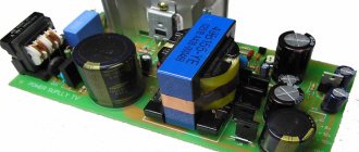
- The equipment does not turn off. Whether a CRT TV or a modern LCD model has broken down, this malfunction is associated with a blown fuse. Only different models have details that are distinctive from each other. You should also pay attention to the diode bridge - perhaps it was the one that burned out.
- In both domestic and imported models, the potential for which the posistor is responsible can often go astray.
- If the monitor of a plasma TV is broken, then the problem most often lies in interference or changes, light or dark stripes may appear, and the color changes while watching a program or movie.
- The problem may also be a broken cord or a faulty socket.
If we take into account all the troubles listed above, it is worth saying that the most complex breakdown is considered to be a screen malfunction.
For example, light reflections appear on your monitor after liquid gets on the matrix or the TV is hit, then it is better to take it to a TV service center. Here it will definitely be repaired, and if the warranty period has not expired, then it will be repaired free of charge or at a reduced price. See also -
What to do if the TV does not turn on?
Progressive and interlace scanning
Progressive scanning is the principle of displaying images on a display and is an alternative to interlace. With progressive scanning, each frame of the video is a full-fledged image, not a compressed one - the image consists of the number of horizontal stripes specified in the resolution height parameter. For example, if a user is viewing a movie in 1080p quality (“p” for “progressive”), then the actual frame height is 1080 pixels.
Using interlaced scanning means that every first frame of the video sequence will consist only of even lines, and every second - of odd ones.
Thus, when viewing content in interlaced mode with 1080i quality (“i” - “interlace”), the image height will not be 1080 pixels, but only 540.
Thanks to this principle of creating video footage, you can almost halve the size of the disk space occupied by the file.
The main disadvantage of interlaced scanning is the relatively low picture quality, which creates additional strain on the viewer's eyes.
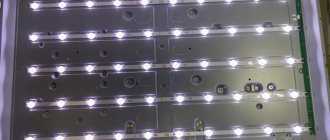
LCD screen - repair details!
You can try to fix some TV malfunctions yourself. And it doesn’t matter here whether these are LCD, LCD or LED models; you don’t need to call a technician if you are confident in your abilities. But caution never hurts, because such TV models are not cheap, and without repair experience or knowledge in this area, you can only cause harm and aggravate the breakdown.
Before you start repairing LED or LCD TVs, you must carefully read the instructions, and also study the operating principle of your model. Anyone, even someone far from this area, will understand that the repair of TVs such as LCD or LED will differ from kinescope models. In the latter case, you are guaranteed not to encounter a faulty posistor. The main thing here is to identify the problem, why doesn’t the backlight work?
If you are repairing LCD or LED models, then the only difference here will be what kind of backlight is used. If this is an LCD TV, then the backlighting is done using fluorescent or fluorescent lamps. For LED TVs, backlighting is made using LEDs. At this stage, the differences between LCD models usually end.
Image path
The television radio signal from the antenna input is supplied to the input of the tuner TU101, which is controlled by the MK (pin 31, 33 IC01) via the I2C interface (pin 4, 5 TU101). The tuner is powered by a voltage of 5 V (pin 7). The output signal of the tuner (pin 11) with an IF equal to 38 MHz, through the bandpass filter Z101, which forms the frequency response of the IF path, is fed to the input of the amplifier - pin. 6 and 7 IC501 chips. Here are its main functions:
- generating a full color video signal (CVBS) from the IF signal;
- generation of an audio signal from the PFC signal;
- generating AGC voltage for the tuner;
- automatic detection of the color system and decoding of PAL and NTSC systems;
- control of external SECAM decoder (IC502);
- extracting the brightness signal from CVBS;
- formation from color difference signals: brightness signal and primary colors (RGB);
- switching of RGB signals and on-screen menu (OSD), their amplification to the level necessary to control output video amplifiers on transistors Q901-Q903;
- extracting clock pulses from CVBS and generating horizontal scan trigger pulses and sawtooth voltage to control vertical scanning;
- receiving and processing control commands from the MK via the I2C interface.
The pin assignments of the TB1238AN microcircuit are presented in table. 3.
Table 3. Pin assignments of the TB1238AN chip
| Pin number | Signal | Description |
| 1 | DE-EMP | audio signal output to attenuator |
| 2 | AUDIO-OUT | Audio output |
| 3 | IFVCC | Analog part supply voltage 9 V |
| 4 | AFT OUT | AFC signal output |
| 5 | ID GND | General |
| 6 | IF IN | IF signal input |
| 7 | IF IN | IF signal input |
| 8 | RF AGC | AGC voltage for tuner |
| 9 | IF AGC | AGC voltage for amplifier |
| 10 | APC FILTER | Automatic Image Adjustment Filter |
| 11 | X-TAL | Quartz crystal 4.43 MHz |
| 12 | Y/C GND | General channels of brightness and chrominance |
| 13 | Ys/Ym | HALF TONE mode control input |
| 14 | OSD R | OSD signal input R |
| 15 | OSD G | OSD signal input G |
| 16 | OSD B | OSD signal input B |
| 17 | RGB VCC | Video processor supply voltage 9 V |
| 18 | R OUT | R signal output |
| 19 | G OUT | G signal output |
| 20 | B OUT | Signal output B |
| 21 | ABCL | Input of brightness control and beam current limiting circuits |
| 22 | V RAMP | Vertical scan GPN capacitor |
| 23 | VNFB | Vertical scan OX pulse input |
| 24 | V OUT | Vertical ramp voltage output |
| 25 | V AGC | Vertical scan AGC filter |
| 26 | SCL | I2C interface synchronization bus |
| 27 | S.D.A. | I2C interface data bus |
| 28 | H. VCC | Horizontal scan oscillator supply voltage 9 V |
| 29 | ID/SW OUT | SECAM signal switching output |
| 30 | FBP IN | Login SIOH |
| 31 | SYNC OUT | Sync output |
| 32 | H.OUT | Line scan trigger output |
| 33 | DEF. GND | General |
| 34 | SCP OUT | SCP Dual Level Gating Output |
| 35 | VIDEO SW | CVBS video output for SECAM decoder |
| 36 | DIG VDD | Power supply for the digital part of the circuit (5 V) |
| 37 | SECAM BY | SECAM BY signal input |
| 38 | SECAM RY | SECAM RY signal input |
| 39 | Y-IN | Brightness input Y |
| 40 | H.AFC | AFC filter 1 |
| 41 | EXT YIN | Video switcher input 1 |
| 42 | DIG. GND | General digital part of the circuit |
| 43 | TV IN | Video switcher input 2 |
| 44 | BLACK-DET | Black Enhancement Circuit Filter |
| 45 | With IN | External chrominance input |
| 46 | Y/C VCC | Video processor supply voltage 5 V |
| 47 | DET OUT | Video detector output |
| 48 | LOOP FILTER | Connecting the AGC filter |
| 49 | GND | General VCO |
| 50 | VCO | VCO reference circuit |
| 51 | VCO | VCO reference circuit |
| 52 | VCC | Supply voltage 9 V VCO |
| 53 | LIM IN | IF signal input |
| 54 | RIPPLE FILTER | Anti-aliasing filter |
| 55 | EXT AUDIO IN | External audio input |
| 56 | FM DC NF | Audio power filter |
The video processor switch input (pin 14-16 IC501) can receive OSD-R, G, B, teletext signals TXT-R/G/B or external SCART-R/G/B signals. The selection of the required signals is carried out by the IC751 switch, controlled by the FB-ID signals (pin 39 IC01), TXT-FB (pin 8 P701B) or SCART-FB (pin 16 PJ201). Output video signals of primary colors with pin. 18,19, 20 IC501 via pin. 2, 4 and b connectors P901B are supplied to the transistors of the output video amplifiers Q901-Q903, which are powered by a voltage of 180 V from the horizontal scan circuit. In addition, through contact 1 P901V a bias voltage of 12 V is supplied to the video amplifiers, which determines the operating points of the transistors. There are no adjusting elements of video amplifiers in the circuit because all adjustments are performed by the IC501 video processor in service mode using a microcontroller via the I2C interface.
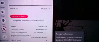
What is the cause of LCD TV malfunctions?
The only problem is that there is no power; to check this on the LCD TV, you can do the following with your own hands:
- open the back cover of the model;
- remove the wires connected to the matrix;
- connect the working lamp to the contacts;
- There are also LCD models that provide more than one light source. In this case, it is necessary to test all sources. Just dismantle the matrix and connect your TV to the network - you can see which LED is the problem.
When a broken lamp in an LED or LCD TV is identified, it must be replaced. This stage requires maximum accuracy from the master, as well as special attention. In some cases, the lamp can be removed without removing the matrix; you just need to move the protective elements with the rubber gasket and pull out the lamp using a soldering iron. In a similar way, you need to install a working light bulb. Now we can congratulate you - you have repaired your LCD TV yourself! Just pay attention to one important nuance - the new light bulb must fully meet the parameters and dimensions of the broken one!
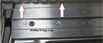
To repair TVs yourself, look carefully at the matrix! If there are “unhealthy” stripes here, then the breakdown lies in the matrix. Have a new part? Then everything is simple! You change it and turn on the TV, if it works, then you have accurately identified the problem.
If the reason for the breakdown of LCD TVs is the screen, then it is best to purchase new models of LCD or LED equipment. It is not recommended to change the screen of LCD and LED models, as this is impractical! This also applies to the LCD matrix.
What could be the problem with plasma TVs malfunctioning?
If you need to repair plasma TVs, then follow the same procedure as described above. Just adapt it to your specific case. This description can be applied to any model of plasma TV, just stock up on the necessary tools in advance. See also -
How to choose a TV for your home in 2021?
Recommendations from our experts
We have prepared several recommendations for CRT TV owners to help avoid breakdowns:
- Do not set brightness and contrast to maximum;
- connect equipment through a stabilizer: this will protect the power supply and other elements from burning out due to voltage fluctuations;
- do not give the receiver a “round-the-clock marathon”, turn it off when unnecessary (this will extend the working life of the device);
- You should not look for the source of the breakdown on your own and try to fix it. All complex work should be entrusted to a telemaster.
By following these recommendations, you can increase the service life of the picture tube receiver and avoid the occurrence of many defects in its operation.
Microcontroller
MK IC01 performs the function of controlling all chassis components. The operation of the MK is ensured by the quartz resonator X01 (pin 19, 20), the reset circuit IC03 and the non-volatile memory IC02. The purpose of the microcircuit pins is presented in table. 4.
Table 4. Pin assignments of IC01 chip
| Pin number | Signal | Purpose |
| 1 | H-SYNC | Horizontal sync input |
| 2 | V-SYNC | Vertical sync input |
| 3 | LED | LED output |
| 4 | CC/AV-ID | Camera/LF input source identification input |
| 5 | POWER | Power supply control output |
| 6 | ABS | Alarm input |
| 7 | MNT-CTL | Switching sound to SCART (TV/AV) |
| 8 | DEGAUSE | Output for turning on kinescope demagnetization |
| 9 | EYE | Light sensor signal input |
| 10 | IR-IN | Signal input from photodetector |
| 11 | SD-IN | Video signal identification input |
| 12 | TURBO | Tuner tuning mode switch output |
| 13 | TBS-SW | Tuner AGC time constant switch output |
| 14 | 4.5M | Standard M |
| 15 | S-MUTE | Sound blocking output {not used) |
| 16,18,21 | GND | General |
| 17 | FS | Service mode switch input |
| 19 | X-IN | Quartz crystal 8 MHz |
| 20 | X-OUT | Quartz crystal 8 MHz |
| 22 | VCC | Supply voltage +5 V |
| 23 | 0SC2 | Generator output 1 (not used) |
| 24 | 0SC1 | Generator input 1 (not used) |
| 25 | RESET | Reset input |
| 26 | A.F.T. | Tuner fine tuning control input |
| 27 | A.G.C. | AGC voltage input |
| 28 | F8-ID | Blanking pulse input from SCART |
| 29 | KEY1 | Keyboard Scan Input 1 |
| 30 | KEY2 | Input 2 keyboard scan |
| 31 | SDA1 | I2C interface data bus |
| 32 | CCTV-CTL | TV/Camera Mode Switch Output |
| 33 | SCL1 | PC interface synchronization bus |
| 34 | CCTV-ID | CCTV signal identification input |
| 35 | Ym | Switch output "1/2 image brightness" |
| 36 | MELODY | Audio information signal output |
| 37 | 51 | TV standard switch output 1 |
| 38 | SO | Output 2 TV standard switch |
| 39 | FB | OSD blanking pulse output |
| 40-42 | BGR | Video outputs of OSD circuit |
Teletext module
A teletext module can be installed on the MS-994A chassis, which is connected via connectors P701B, P702B. The module is based on an IC701 chip of the SAA5281 type, which has 8 Kx8 RAM for 8 teletext pages. It is designed to work with the 625-line WST (World System Teletext) standard. In addition, the chip decodes VPT (Video Recorder Programming) signals. It is controlled by the MK via the I2C interface (pin 24, 25). To operate IC701 on its pin. 9, a TXT-CVBS video signal is received from IC501 (pin 35). At the outputs of the microcircuit, teletext signals R, G, B (pin 16, 17, 18) and a blanking signal (strobe) TXT-FB (pin 20) are generated, which are fed to the switch IC751, and from it to the video processor IC501.
To power the teletext module on pin. 3 P701V is supplied with 9 V voltage from the power supply. The IC701 chip is powered by a voltage of 5 V from the stabilizer IC702.
Sound path
The main part of the audio path is located in the IC501 chip. To isolate audio signals of different standards, use the IC151 switch with filters F151-F154, controlled by MK signals: SO, S1 and M4.5 (pin 38, 39, 14). The IF signal from the output of the video detector (pin 47 of IC501) is fed through buffer Q507 to the inputs of filters F151-F154 connected to switch IC151. Output signal FCZ with pin. 3 IC151 is supplied to the input of the demodulator - pin. 53 IC501. The audio output from the demodulator is amplified and fed to the INT/EXT switch (inside IC501) to select the appropriate signal. External sound signal to pin. 55 IC501 comes with SCART or Cinch connectors. The audio signal source selected by microcontroller IC01 via the I2C interface is removed from the pin. 2 IC501 and is fed to the input of the audio frequency power amplifier (UMZCH) - pin. 5 chips IC601 type TDA7253, which is a single-channel push-pull class AB amplifier with short-circuit protection and a MUTE sound blocking input (pin 3). From its output (the output signal through the coupling capacitor C605 and connector P601 is supplied to the dynamic head. The UMZCH is powered by a 20 V power supply (S-VCC).