Whatever display device you use in your home theater, be it a plasma panel, an LCD panel or a projector, it is necessary to calibrate it to obtain the highest effect, only then will you get the maximum picture quality of the movie being played on the screen. To achieve this goal, there is a special calibration program Display Basic Adjustment Test, which can be downloaded from this link . The downloaded file is an image that must be burned to disk or mounted into a virtual drive, for example, using the free version of Daemon Tools . When playing it, five test images will be displayed sequentially on the screen, which will help calibrate the TV with an aspect ratio of 16:9 and a resolution of up to 1366x768 pixels inclusive. If you are going to calibrate a device that supports 1920x1080 pixel resolution, use the AVEC.iso . It must be recorded on a Blu-ray disk and then played back using a Blu-ray player, or on a PC, mounting it into a virtual BD drive using Daemon Tools. For subsequent playback, you can use the Cyberlink PowerDVD 11 software player.
Preparing to calibrate a TV or projector
When calibrating, you must turn off the room lights or ensure the lighting conditions in which you usually watch movies. It is usually recommended to turn off artificial lights and close the curtains while watching. In addition, you should set the original factory settings for brightness, contrast and gamma. If you have any additional technologies enabled that improve image quality, such as noise reduction, turn them off. This applies not only to the TV, but also to the player.
3D LUT calibration options
CalMAN and 3D LUT
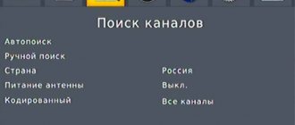
The CalMAN system offers many options for calibrating 3D LUTs. You can choose from 100-point calibration (Lightning LUT), 3500-point calibration (iRP LUT), or create a LUT based on primary color readings. The 3500-point calibration option requires over one hour of measurement (using the best colorimeters). This calibration option is likely to be used by the most advanced high-quality image proponents or studios.
LUT calibration based on base colors
The fastest option is to calibrate the LUT based on the base colors. This is the simplest method. The method is based on the measured performance of a given calibrated panel and should be more accurate than factory calibration based on the average value. It is worth noting that it is currently unknown how noticeable the differences between different calibration methods are.
Calibration using HDR10 and HLG
The new LG TVs are also the first to offer color gamut calibration when using HDR10 and HLG. HDR calibration has always been a challenge, but now it's becoming possible in some ways.
This gamma calibration method was developed by LG, Dolby and CalMAN to calibrate LG 2021 OLED models to the Dolby Vision standard. Although, according to experts, the effectiveness of this procedure is somewhat doubtful.
3D LUTs in SDR, HDR and Dolby Vision
It is also worth noting that modern LG TVs allow you to calibrate the image not only in the “Cinema” mode, but also in other modes. Of particular note is the Low Latency mode for SDR, HDR and Dolby Vision playback, which now has the same calibration capabilities as the other modes. This will be a good addition not only for game lovers, but also for quest developers.
To conclude the topic of 3D LUT calibration, let's summarize.
We assume that 2021 will be a turning point for LG in terms of color reproduction and calibration capabilities. This topic has been well developed and improved by them, and the 3DLUT function is a breakthrough in technology that allows it to overtake competitors QLED TV. We can say that with this technology the line between home 4K TV and studio equipment is blurring. 3D LUT calibration options 2018-02-01T17:50:37+03:00 VoVVideo If you are planning to purchase an LG OLED 8 series TV or a fresh LCD 2021 model, then it is worth learning about the technology that has appeared in the latest models in the field of accurate color reproduction. One of the features that is trending right now is direct access 3D LUTs. Now LG has become the second manufacturer in…VoVVoV AuthorUltraHD
Calibration of TV, projector
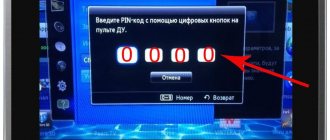
Play the test DVD in your player. You will see a specific sequence of five different images. If you skip any of the setup steps, you will not be able to obtain optimal picture quality. When adjusting brightness and contrast, first reduce their value to a minimum and gradually increase it until the test conditions are met. When adjusting color, set the parameters to the middle position. Factory settings typically have a very high color temperature, resulting in predominantly blue tones in the image. allows you to adjust the color temperature, set its value to <6500K> , <Warm> or <Neutral> . On the contrary, the image sharpness of most TVs is initially adjusted quite well. The final image check is performed in the fifth step. You need to make sure once again that all previously selected settings are correct. This step also allows you to check the operation of the sound system.
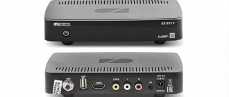
For those who want to take TV calibration seriously, the best option would be a special calibrator - Datacolor Spyder 4 TV HD 2 costing ≈4000 rubles. Thanks to it, you can significantly improve the quality of the TV image by making the necessary adjustments.
Instructions for calibrating the monitor and a review of calibrators with calibration programs are located in the following articles:
- Monitor calibration | Step-by-step instruction
- Monitor calibrators | Calibration programs
Finalization of the DIY POV LED ball constructor
Good afternoon, dear reader. Perhaps you came across this article because you want to save yourself from the need to see hieroglyphs in your watch, collected with sweat and blood. In this article you will find everything you need! But let's start from the very beginning.
A few months ago I put together a DIY LED ball constructor, the “ball” is actually formed due to the inertia of vision and the rapid movement of an arc of LEDs. This effect is abbreviated as POV or persistence of vision or inertia of vision. The assembly process and first impressions of the set can be seen below:
From the very beginning, I noticed many design flaws and began to correct them one by one.
1. Lack of foundation
Indeed, the set looks as if it should be mounted on a “certain” base in which all the wires and the power board will be hidden. In practice, there is no such basis in the set. So we need to do it!
I took a sheet of chipboard from a piece of an old shelf and sawed off 4 pieces to fit the size of the largest acrylic square. Then I glued it together with PVA glue. There should be a place in the center of the structure where we will hide the power board. After the glue has dried, you need to drill a hole for the power connector and for the wires. I haven’t decided on the design of the toggle switch yet, so I just shorted it and temporarily sealed everything with tape. As they say, nothing lasts longer than temporary. Now we simply screw the acrylic square to our base; for this there are already 4 holes in it.
Ideally, the base should be well adjusted, sanded and painted.
2. Imbalance
Due to the fact that the design of the kit involves gluing the coils with hot glue, the task of balancing the rotating board is quite tedious. However, during gluing, I tried to make the drops of glue as symmetrical as possible, so balancing in my case ended with the selection of a weight that is attached to the technological hole in the board opposite the LED arc. The kit includes a stand for this, but it turned out to be too heavy so I picked up a stand that was a little lighter. Balancing can be done using small drops of hot melt glue, but this process will take much longer.
3. Hieroglyphs
It’s clear that the set was created by the Chinese, but it’s completely unclear to me why they didn’t make an English-language interface in the software and firmware. Full of enthusiasm, I set about implementing this. I attach everything that I got to this article. If you improve my code, I will be very happy! To do this, go to the page of this article on the forum and submit your version with modifications there!
Link to the original Chinese archive at the end of the article!
So, first, a little about the sad. The archive contains a lot of useful software and source code, which made me think that the Chinese simply made everything open and therefore did not bother with English translation. How wrong I was! In fact, the most complete firmware in the archive does not contain the code that is responsible for calibrating the time, updating inscriptions and images... “Because the Chinese!”
Therefore, I decided to give up on backward compatibility with old software and decided to make my own firmware and my own software for calibrating time and uploading images to the “ball”. Here, nevertheless, I would like to say thank you to the person who added the datasheets to the archive, including the 4 buffer chips that are on the board. Only thanks to this I understood how they work in general.
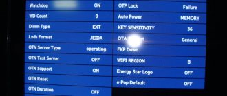
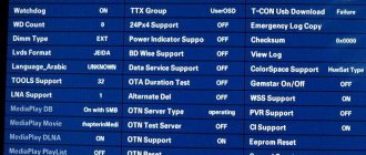
First, let's figure out how the firmware is uploaded to the assembled kit. To flash the microcontroller we will need a UART adapter, for example a USB-UART adapter on the CH340 chip. The board has a 4-pin connector: ground, RX, TX and power; it must be connected to the UART port and run the program for firmware stc-isp-15xx-v6.70. We set the necessary settings (in the picture below) and select the hex firmware file, then click the Download button. And we see that nothing is loading. The fact is that the bootloader is loaded in such a way that to flash the firmware we need to first disconnect the ground contact, then click Download, and then connect the ground. It’s quite a tedious task, so for the debugging process I built a cable with a toggle switch on the ground.
Now you need to get into the firmware. Theoretically, you can correct the hex file, but it seemed to me that this was not a constructive approach and I went into the source code. We open the most complete project for kale, which is also in the original archive for the designer. The project contains several connected “sys” files, each of which contains various functions.
task.c is the main code. It implements the main function of the microcontroller and control.
Showtime.c - as you might guess, the functions for displaying date and time are written here, as well as an array of characters used for this.
DS1302.c - it contains the functions of working with the time chip.
IR_reseve.c - functions for working with an infrared remote control.
zimo.c - where arrays of text and images converted for display are written.
Let's stop at the output of the date and time and start editing the code.
To begin with, I decided to swap the display of date and time so that the time was shown “along the equator”, and the date above it. And then I decided to separate the month and day from each other simply by a space. But I still replaced the hieroglyphs indicating day, month, hour, minute and second with English words so that they would be displayed during setup.
And then the moment came, my first awareness of the code. And now we will figure out what and where, and then we will continue to edit our firmware.
To begin with, how to construct our image?
As I said earlier, in the first video, the image is obtained due to the inertia of the eye. The arc of LEDs rotates continuously and after a certain discrete time the position of the burning LEDs in the arc changes. At the first moment of time one, at the second it has changed, at the third it is different again and this happens at high speed, due to which our eye perceives the whole picture. This is called mechanical reaming. I tried to make an animation to show this more clearly.
There is also a pair of LED-photodiode on the board, why are they needed? Every time the board passes over the LED, an interrupt is triggered and the microcontroller resets everything it was doing and starts drawing the frame again. It all works in such a simple way. But there is another point that is not so “transparent” - this is the output of the code to the LEDs. Looking through the code we see the following lines:
Send_data_chang(0x00,0x00,zimo1[j*2+1],zimo1[j*2]); Send_data(0x00,0x00,zimo1[j*2+1],zimo1[j*2]); Send_data(0x00,zimo2[y*2+1],zimo2[y*2],0x00); Send_data_chang(0x00,zimo2[y*2+1],zimo2[y*2],0x00); STR=1;//forwarding data to the output of the microcircuits STR=0; OE=0;//LEDs light up Delay10us(); OE=1;//LEDs go out j++; y++;
At first glance this is complete nonsense, but in fact the code is quite simple. Task.c contains two functions Send_data and Send_data_chang; if you compare them carefully, you can see that the first function alternately sends even (0,2,4..) bits to a certain data line. Send_data_chang differs only in the initial shift by one of all input data, which means it sends odd bits to the line. But all these functions work with one data line, and a reasonable question is how are they separated?
The answer was given by the datasheet for these microcircuits. It turned out that each of them has an SDO output, on which bits appear with a shift of 16 cycles. That is, when you loaded 16 bits of data onto the first chip, then when you load 17 bits (calling the next function), the first bit will appear at the SDO output of the first chip. This means that all 4 microcircuits are connected in series! The input of each subsequent SDI is connected to the SDO output of the previous chip, which is confirmed by a multimeter. But the question still remains: why do we need to send alternately even and odd bits? The question disappears when we look at the layout of the board with LEDs. This is simply due to the method of connecting the LEDs for easy board layout.
After sending 4 packets, the correct code is set on all microcircuits, but it has not yet been loaded into the internal register. We generate a write pulse by setting STR = 1, and then STR = 0. Then we set the resolution input of the microcircuits to zero OE = 0 at this moment the LEDs light up. Next comes a short pause Delay10us so that our eyes have time to see and turn off the LEDs OE = 1.
Now we know how this LED “ball” works. This means we need to clear the firmware of the “Chinese” code and spice it up with comments, but let’s get back to the problems of hieroglyphs. The source archive contains the PCtoLCD2002 program, with which you can convert graphics and letters into codes for loading into the microcontroller. It’s a very useful utility, although it’s Chinese, but it’s not difficult to understand in the slightest degree; below I’ve given an approximate designation of the program settings. Enter the necessary characters, it will be converted into code and copy it to the source. To demonstrate how I do this, you can watch the video attached to this article.
It’s also worth mentioning that there is space on the board for a temperature sensor, but it seems to me that it is unnecessary here and I didn’t bother with it. I will leave the field of activity to the same perverted enthusiasts like me.
Having corrected all of the above, we have a clock with a certain amount of text, but still no pictures. And then I received the second awareness of the code, the final one! In the source code, text and pictures are stored in code arrays, that is, in ROM memory, in the same place as the firmware. And not only can we not change this memory via UART, but the memory size is only 8 KB. However, the microcontroller has as much as 53 KB of EEPROM memory, but the Chinese left it to me to figure out how to work with it. OK.
And here we are saved again by the datasheet for the microcontroller, which contains examples of code with the implementation of working with EEPROM memory and a UART port. Let's read the details. EEPROM memory is divided into pages of 512 bytes. From which we express the number of columns in one frame - 192. Ask why?
Because we need to have an exact value that is a multiple of 512 bytes for one frame in order to simply “walk” through the EEPROM memory, displaying the image without gaps. Accordingly, we should have approximately 200 lines (in the Chinese source code the number 200 is used), but 200 lines gives us 200 * 8 bytes, which is not evenly divisible by 512. The output is a little more than 3 pages. We take 3 pages per frame and count the number of lines: 512*3/8 = 192 lines.
But let's start filling the EEPROM memory from the second page, leaving space for various information in the first. In our case, when sending from the computer to the microcontroller, a code word will first be sent to enter the EEPROM update mode (which we wrote). After this, a number will be sent equal to the number of pages (512 bytes each) that will be filled. And then the computer sends byte by byte of the image, while the microcontroller first clears each page before filling it. Everything is simple and works great! It's hard to put into words what I felt when I finally loaded the image of the xy globe onto the ball!
Now we add the time calibration function. Everything is simpler here, but we must take into account that the time in the memory chip, tens of minutes, hours and seconds, are stored in the second byte. That is, 15 seconds will not be 0b00001111, but 0b00010101. Accordingly, you get the system time, convert it and send it to the UART.
Next, we essentially need to implement the functionality of the PCtoLCD2002 program, convert images into an array and send this array to the microcontroller. We have already learned how to send bytes, but we need to open the image and convert it into the form we need.
I won’t describe the source code in detail, the source code is attached to the article, you can open it and read it. Everything is pretty sad there, but I hope to finalize this project so that it is more universal and convenient. Using this utility, you can open a black and white image (or even several) and it will appear on the monitor as a field of "LEDs", but it must be 192 by 64 pixels in size (although the bottom 8 pixels are discarded... "Because they're Chinese!" and we have 56 LEDs in the arc). After which you can send everything to the microcontroller, only it must be connected via UART to the PC. There is also a calibration button, I also think everything is clear. Click, and the time in the set is set!
To prepare images, you can use any graphics editor. Create a new file with a resolution of 192 by 64 pixels and draw in black and white. Then save the image in bmp format.
Now our watch is ready. Now you can correct my sources, add what you want to them or change the symbols, etc.
Yes, I did not implement the text in EEPROM memory. Why? Because I think this is nonsense and the text looks dumb. But you can put your text in the firmware using the PCtoLCD2002 utility in the zimo1 and zimo2 arrays. By the way, it is more logical and beautiful to display text with pictures.
The project will be developed and updated whenever possible, subscribe so as not to miss it.
Link to the original Chinese archive: https://files.banggood.com/2016/08/SKU343833.rar
That's all for me. Good luck mastering the set, bye!
Attached files:
- PCtoLCD.rar (80 Kb)
- RusDIY.rar (124 Kb)
Tags:
- Light-emitting diode
Outland (2006, fragment 6)
The film tells the story of a stuntman lying in a California hospital in the twenties, who befriends a little girl gifted with a rich imagination and composes for her a grandiose fairy tale about five mythical heroes. This is one of the most colorful films and one of the best Blu-ray discs in our collection.
Dazzling shades of magical landscapes, colorful costumes; the ritual singing scene is a real feast for the eyes and a harsh test of the richness of the colorful palette of your TV. Bright green gardens should clearly contrast with desert landscapes, the vast expanses of which will also allow you to appreciate the depth of the image of a TV or projector.
Casino Royale (2006, fragment 2)
One of the most demanding scenes on TV is the motorcycle chase in Skyfall, but the parkour-style chase in Casino Royale outshines even that.
Eight compelling minutes of fast-paced, thrilling action, during which Bond and his nemesis leap from crane to crane, require exceptionally fluid motion.
This is done by a motion processing processor that can analyze the image and insert repeated or empty frames to avoid the feeling of unnaturalness. However, be aware that on less talented TVs, high levels of processing may result in blurry halos around moving objects.
Harry Potter and the Deathly Hallows. Part 2 (2011, fragment 12)
The Dark Lord is in near-total darkness: This segment begins with Voldemort and his Death Eaters, dressed all in black, standing on an unlit hillside in the dead of night. And in subsequent scenes there is not much more light. If you see anything other than pale faces against a black background, your TV is doing a great job.
Resist the temptation to turn up the brightness during the Battle of Hogwarts to see what's going on: on average TVs, this will destroy the depth of the blacks and burn out any bright details.
Instead, a quality display should present just the right amount of detail to the viewer while maintaining rich darkness; and when the first volley of magical fire explodes on the protective field of Hogwarts, it must look like real witchcraft.
Murder on the Orient Express (2017)
Kenneth Branagh's newest adaptation of the famous detective Agatha Christie turned out to be quite close to the original. But in one respect it differs from previous adaptations: the film was shot on 70mm film.
Branagh opted for a wide format (taking a few cues from a film he was working on, Christopher Nolan's Dunkirk) and gave the familiar story a luxurious frame; Originally produced in 4K HDR, this film is a truly dazzling spectacle.
The scene in the titular Orient Express, during which we are introduced to all the characters, is magnificent in terms of blacks, detail and color palette.
Vibrant colors, impressionistic lighting and enhanced detail thanks to 70mm film allow your TV to show off all its talents.
Gravity (2013, fragment 2)
Although Alfonso Cuarón’s gripping sci-fi thriller lost the 2014 Oscar for Best Picture to the drama 12 Years a Slave, Gravity’s victory in the Best Visual Effects category was not at all surprising.
The scene of throwing around in space brings out the contrast and detail in dark scenes; the white elements of the spacesuits and spacecraft are located just a few pixels from the bottomless darkness of space. Make sure that on the TV screen the white fragments are strictly separated from the black background, the contours of the Earth look clear and bright, and a scattering of stars of varying brightness is visible when Dr. Ryan Stone (Sandra Bullock) emerges.
Fans of the 3D format will find even more to admire and will eagerly take advantage of the opportunity to immerse themselves in a compelling visual space; If your TV has the right amount of stability and clarity, you'll appreciate the space debris flying in your face and Bullock moving around the screen.
Spider-Man: Homecoming (2017, fragment 10)
The scene aboard the Staten Island Ferry is one of the most spectacular scenes in the Marvel Cinematic Universe. Exciting and funny, with intense action and plenty of one-liners, this superhero meets movie looks stunning in 4K.
You can immediately appreciate the quality of the colors and textures, with the futuristic fabric of Spider-Man's suit contrasting stylishly with the yellow riveted hull of the ferry and the vibrant blue of the New York sky.
And when Spider-Man, the Vulture and then Iron Man take to the air, you can test the power of motion processing and the TV's ability to generate a myriad of fantastic details in 4K resolution.
Dunkirk (2017)
Because of the film's limited locations and its filmmakers' approach to editing, almost any part of this war epic is perfectly suited for our purposes. Texture, color, contrast, motion control, detail of light and dark objects - all these components of any film in this case are taken to the limit; Shot in IMAX, Dunkirk fills the entire screen with no black bars at the top or bottom.
It is best to consider the episodes with Spitfires. In addition to the light and shade of clouds and the sea, which are traditionally tested objects, elaboration of the textures of the pilots' uniforms will allow your TV to show off in all its glory. The costume designers have done a tremendous job on the wardrobe of the entire cast, and good TV can give the viewer a stunningly realistic, tangible and rugged feel of army uniforms and hand-stitched leather.
Look at the dark details of Kenneth Branagh's character's jacket, at the wonderful colors in the scene of a stalled plane landing on endless sands, and at the four flagpoles on the beach at the end of the first fragment, which tremble like sick people on all TVs except those that boast a magnificent motion processor.
Red, green and blue
The most important thing I hope you take away from this article is that whatever you do to make the image more accurate, give yourself time to adapt. At first, your brain will be convinced that the exact color temperature is imprecise. Trust that it is accurate and give yourself a few days. After this, you won't be able to go back to the cool, bluish color temperatures of lower quality, uncalibrated TVs.
If you are a do-it-yourselfer, then with the help of an installation disk and a little time you can make your TV almost completely ready for use. A good calibration will take you the rest of the way and make your TV look its best. For most TVs, hiring a professional won't make much of a difference, but if you want to make sure your new TV looks its best, it may be worth it.
Note: This article was published in 2011 but has been updated in 2021 with current information and links.
In addition to lighting TVs and other display technologies, Jeff Morrison leads photography tours of cool museums and locations around the world, including nuclear submarines, massive aircraft carriers, medieval castles, aircraft graveyards and more.
You can follow his exploits on Instagram, YouTube and his travel blog BaldNomad. He also wrote a best-selling science fiction novel about city-sized submarines, as well as a sequel.
Best Walking Shoes for Women in 2021
Best Wireless Headphones and Bluetooth Headphones for Making Calls
Alien: Covenant (2017, fragment 1)
A white room with a black piano, one man dressed all in white, and another in all black - this is clearly not the scene against which you can test the color rendering of a TV or the performance of the motion processor. But the beginning of a film from the Alien franchise is ideal for assessing contrast and detail.
On an average-quality screen, this picture will look like a banal monochrome, but an excellent HDR display with the correct lighting level will allow you to see so much in the light and dark areas of the frame that this will allow you to talk about the rich palette of the image.
Pay close attention to the textures: the actors' clothing, the marble of the statue, the polished concrete floor, the lacquered finish of the piano and the fine porcelain tea set - none of this should be lost. And to check out the detail in 4K resolution, take a closer look at the characters' skin in close-ups and at the luxurious view from the window onto the lake shore. This is a very effective and expressive example of cinematic art.
How to find calibrators
Two major companies train people to become professional calibrators: the Imaging Science Foundation and THX. You can find calibrators in your area using these links. Best Buys Geek Squad also promotes ISF-certified calibers, although the company tells us it is phasing out this activity nationally as of July 2021. Your local Best Buy may still offer sizing services, but not all do.
I am an ISF certified calibrator myself and have completed training. So does senior managing editor and television commentator David Katzmaier. I have not received THX training, but am familiar with it.
Both courses teach students the basics of TV setup and the benefits of calibration. They are then shown how to calibrate the TV. THX claims that its course is more "practical", although both courses do a great job.
How to adjust picture clarity on TV?
Many TVs still apply the so-called “overscan” to the image. That is, they leave about 3% of the frame beyond the edges of the screen, “cutting off” the edges of the image. In our era of digital sources, this is no longer so relevant. The best option is when the boundaries of the image clearly coincide with the boundaries of the TV matrix. In this case, if you have a Full HD TV and you are watching a 1080p video source, there is a clear correspondence between each pixel and the image gets maximum clarity.
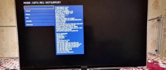
So, you need to run the "Sharpness & Overscan" template from the AVS HD Rec test disc. 709, which is located in the “Basic Settings” section at number 5. The test image looks like this:
Now you need to adjust the image scale so that a white frame is visible around the perimeter of the picture, and overscan is completely turned off. To do this, you may have to dig a fair amount into the TV settings, since almost every manufacturer does this differently. We will give some examples: