Troubleshooting on Sony Bravia TVs
Smart TVs from the Sony Bravia line, like any other household appliance, break down. This does not happen very often, but since we are talking about a high-tech product, breakdowns of these devices have their own characteristics. In particular, many of the problems are similar to computer ones. This means that the technician who will have to repair the Sony KLV 32s550a TV must have a good understanding of the software.
This TV may have some problems
One of the main reasons for problems with smart TV is its integration with Internet networks, both wireless Wi-Fi and wired Internet. This integration creates a risk of virus infection. The latter can cause:
- lack of response to the remote control;
- lack of image;
- lack of sound;
- inability to find the antenna;
- unexpected shutdown.
But the impact of viruses on the operation of software is not the only problem that owners of such TVs have to face. Mechanical damage is an equally common cause. The most common breakdowns due to impacts, falls and exposure to water:
- TV not turning on with blinking indicator;
- not working buttons;
- the picture becomes monochromatic;
- strong snow-like noise;
- the screen turns black or white;
- TV turns on or stops working after turning on for no reason;
- no decimeter channels;
- violation of synchronization between picture and sound;
- problems with image scaling relative to screen size;
- linearity violations;
- clear signs of physical damage on the case.
In this video you will learn more about repairing such a TV: Every time, to find out the cause of the breakdown, correct, professional diagnostics is necessary. For it, a number of methods and special equipment are used, available only to masters who deal with such equipment. We're talking about:
- microscopes of binocular models;
- vacuum grippers;
- oscilloscopes;
- multimeters.
In addition to these tools, software specialists conduct software testing.
There are breakdowns that cannot be corrected by other methods other than replacing the broken part. This is the case, in particular, with matrix failure. Any damage cannot be repaired. Be it chips on the glass, cracks or internal damage to the display unit.
In addition to the matrix, the X1 Extreme processor, which is responsible for exactly how the image is displayed, also breaks down. It is on this that the increase in resolution to 4K HDR (that is, 3840 by 2160 pixels) depends. Without 14-bit signal processing, colors would be segmented and gradients would not be smooth enough. Thanks to the processor, even with an 8-bit source, you can watch videos with maximum quality. Replacing a processor can be quite expensive.
In addition to the processor, the following are subject to replacement:
- power circuits;
- backlight lamps;
- kinescope modulators.
Attention! All these and some other parts cannot be repaired if damaged. Which requires contacting a licensed service center.
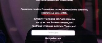
Identifying the causes of a network error
The cause of network error 1107, which indicates a loss of Internet connection, may be a malfunction of the TV itself or the servers. First, you should contact technical support and, having explained the situation in detail, wait for an official response. Perhaps the server is undergoing maintenance or repair work and you need to calmly wait a while to return to watching TV.
It is also advisable to contact the provider and find out if there are problems on their side. If everything is fine on the servers and the Internet service provider, then perhaps there is a malfunction in the gadget itself or the devices connected to it. We can take several steps to improve the operation of the Sony Bravia TV. You just need to follow all instructions carefully.
Error code 2200 may also occur in Sony Bravia.
Doesn't turn on
Unfortunately, the owner of any TV device at some point is faced with the question of why the TV does not turn on. There can be quite a lot of reasons for this. Some of them are determined by the characteristics of the light signal of the indicators burning on the front panel.
There are three such indicators:
The first of them indicates a lack of power, while the second indicates that the timer is on. The third one informs you that the TV is on. But, as noted above, some features of their operation may indicate the type of failure that leads to the inoperability of the TV.
There are 3 alert indicators
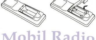
So, if the light on the panel is blinking, then this is one of the main signs of problems: a blinking light, especially if the red indicator is blinking, indicates the presence of a software error. In some cases, the problem can be solved independently. For this:
- the TV is completely disconnected from the network, even the cable is disconnected;
- after a five-minute pause, turn it on again.
If the equipment still doesn’t work, then they turn to the experts. If the indicator flashes in series of 8 flashes, then the settings reset procedure is carried out.
A constantly flashing orange light is a clear sign of a software update in most cases. The latter can only begin if the smart TV is connected to the Internet. A loss of Internet connection sometimes causes the procedure to freeze, which can be corrected by disconnecting from the network.
If a consumer is faced with a non-working TV due to a software update, he should consider that:
- at this time the remote control does not work;
- the normal duration of the procedure is up to ten minutes, so patience is required;
- The TV cannot be disconnected from either the power supply or the Internet.
If the TV does not turn on at the end of the procedure, this is often a sign of incorrect installation of programs. Help from a professional is the best solution.
Sometimes the TV turns off spontaneously when the screen goes out after a couple of minutes of operation and, having gone out, does not want to turn on again. Most often, this problem is solved by resetting all settings to factory settings, since its cause is software conflicts.
Main technical characteristics
Television signal systems: B/H/G, D/K, I, L.
Color systems:
- PAL;
- SECAM;
- NTSC 3.58 MHz; NTSC 4.43 MHz (video input only).
Received channels:
- VHF: E2-E12, R1-R12;
- UHF: E21-E69, R21-R69;
- Cable: SO1-SO5, S1-S2O;
- HYPER: S1-S41.
Power consumption from the network, W:
- models KV-20WS1A/B/D/E/ K/R-70;
- model KV-20WS1U - 92.
Maximum output sound power - 2×8 W; subwoofer - 20 W.
Other features: the presence of teletext, fasttext, NICAM audio decoder.
Structurally, the chassis consists of the following boards:
- A - main board;
- C— kinescope board;
- U - board of quenching pulse generators;
- K - subwoofer amplifier board;
- N - input/output board for audio and video signals.
How to fix error 2200
Since for a domestic user error 2200 on Sony Bravia is in many cases associated with the activities of Roskomnadzor, it will often be enough to simply wait for some time (usually up to a couple of days). During this time, Roskomnadzor itself usually unblocks addresses associated with servicing network tools not related to Telegram, and their operation is restored in full.
Also, as an alternative, do the following:
- Turn off your router or modem for 1 minute and then turn it back on. Wait at least 5 minutes until your router restores a normal Internet connection;
- Unplug your TV's cord from the outlet and then plug it back in, this may help resolve error 2200 on Sony Bravia;
- Test your Internet connection and check the network status (should be “OK”). This is accomplished by pressing the “Home” button on the remote control, and selecting “Settings” – “Network” – “Network Setup” – “View Network setting and status” – “Check Connection” – “Yes”. If the test result is not “OK”, then your Internet connection is incorrect and needs to be configured accordingly;
If the connection is stable, the status should be “OK”.
Then you need to update the Internet content. Press “Home” on the remote control, and follow the path “Settings” - “System settings” - “Settings” - “Network” - “Update Internet content”;
Enter the following DNS addresses
- Set the correct date and time. Go to your TV's settings and set the correct date and time. For example, to set the clock, click on “HOME”, then select “Settings”. Select “System Settings” - “Clock/Timers” - “Set. Hours".
Also make sure that the "Accept network/broadcast operator time" option is not enabled.
- If you are using a wireless Wi-Fi connection, then try using an Internet connection via an Ethernet cable as an alternative;
- Update your software version. You can see how to do this on the Sony website. ru;
- Reset your TV to factory settings. Despite the radical nature of this solution, according to user reviews, it is ineffective.
Services and warranty for repairs
Fixing system failures is carried out at home. An engineer comes to the user, connects to the OLED TV via Wi-Fi, configures it and updates the firmware. To receive a discount on service, leave a request on the main page of the site. Order an outgoing call to clarify questions regarding the restoration of Sony Bravia. The call center is open 24 hours a day, 7 days a week, during the conversation the operator will provide a comprehensive, free consultation. We offer our services to residents of more than 15 cities in Russia.
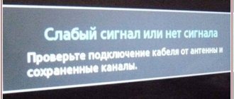
No image
A fairly common problem with all smart TVs is the absence of an image on the TV screen. At the same time, we are not talking about the case when it does not turn on at all, but about the situation when there is sound but no image.
There are two possible reasons for such a breakdown:
- problems with the power supply;
- problems with the backlight inventory.
In the first case, the only solution is to replace the broken block. Secondly, there are two possible solutions. In the first case, the faulty LED is excluded from the circuit without replacement. In the second case, they change the LED strip.
Important! In some cases, more serious matrix malfunctions are possible. To identify them, you will need professional diagnostics, which on average costs about a thousand rubles.
Test mode
To enter test mode, press the TEST button twice. To exit the test mode, press the 0 button twice, then TEST and TV, or switch the TV to standby mode. The list of test mode commands is given in table. 7.
Table 7
| Team | Description |
| 00 | Exiting test mode |
| 01 | Set maximum contrast |
| 02 | Set minimum contrast |
| 03 | Set volume level to 35% |
| 04 | Set volume level to 50% |
| 05 | Set volume level to 65% |
| O6 | Set volume level to 80% |
| 07 | Maximum brightness and contrast |
| 08 | Set analog controls to default values: program number - 1, volume - 35% |
| 15 | Read factory settings (brightness, contrast, hue, volume, sharpness and color values) from the microprocessor ROM and write them to non-volatile memory (NVM) |
| 16 | Save current settings as defaults |
| 17 | Allow/disable clarity adjustment |
| 19 | Set priority for RGB signals |
| 22 | Additional color adjustment (different values for PAL and SECAM) |
| 23 | Additional brightness adjustment |
| 24 | Enable priority of RGB signals |
| 25 | Enable D/K system |
| 26 | Enable I/U system |
| 27 | Enable I/I' system |
| 28 | Enable B/G system |
| 32 | Set contrast to 50% |
| 36 | Mute mode (MUTE) |
| 37 | Disable display of service information on the screen |
| 38 | Switch to G2 accelerating voltage setting mode |
| 39 | Additional brightness adjustment |
| 41 | Initializing Non-Volatile Memory (NVM) |
| 43 | Initializing Geometric Settings |
| 48 | Set the NVM test byte to 44h |
| 49 | Erase test byte |
| 51 | 60/100 programs |
No backlight
Among the breakdowns that Sony Bravia owners have to deal with, TV malfunctions related to backlighting are one of the most common. Its main symptom is a constantly flashing red light in the absence of an image. This means that, when turning on his device, the owner is faced with the fact that it responds inadequately to the remote control. Additionally, sometimes error message 13 appears.
There may be no backlight for a number of reasons
This breakdown can only be solved by replacing the light bulbs. The safest way to get new light bulbs is to contact a service center. Although, with proper skill, independent repairs are possible. The main problem that you will have to face in this case is the correct identification of the lamp that has broken. The fact is that the TV has protection that does not allow this to be done without special equipment.
First of all, they look for a way to bypass the protection. The easiest way to do this is to eliminate the sensor responsible for unbalancing the lamps. On the TV board it is marked as balancer_err. To make it stop working, the first pin of connector CN67 is disconnected from this connector, thus disconnecting the inverter from the power supply.
Disabling the protection sensor allows the TV device to turn on in normal mode. To accurately identify the problem lamp, turn on the green and white field signal. After that, replacing the light bulb itself is quite simple.
Extraneous sounds
Humming, clicking, short beeping, uncharacteristic clicking when the device is turned on means:
The clicks that you hear are the sounds of the blocking system (the relay is activated), the main task of which is to prevent the TV from completely failing.
In such situations, there is no point in trying to fix the malfunction yourself - only experienced TV technicians can carry out a set of necessary works, which includes:
It is necessary to call a specialist in case of a burnt-out microcircuit or power supply - these breakdowns are usually accompanied by a whistle (damage to the capacitors on the board) and a hum.
The essence and causes of dysfunction in Sony Bravia
Typically, error 2200 occurs when trying to connect to the Internet, or while such a connection is running, when it suddenly disappears.
Sony experts believe that the reasons for error 2200 are:
- Problems with the Internet connection (absent or unstable);
- High load on your local network (high level of traffic);
- Exposure to external electronic devices causing network interference;
- Problems with Sony servers (caused, among other things, by the actions of Roskomnadzor).
Most often, Sony Bravia owners encounter error 2200 when launching the YouTube application on this TV, when the TV signals error 2200. In other cases, when watching a video on YouTube, it suddenly disappears, and the user sees a message about the specified error. error.
Self-diagnosis
Errors detected as a result of the internal diagnostics system are recorded in two ways:
At the first moment after turning on the TV, the microprocessor tries to “free” the I 2 C bus (if the bus is not “released”, then the light tries to establish communication with the corresponding device. If a fault is detected in the device, its number is indicated by the corresponding number of LED blinks. If a fatal error is detected, the TV remains in the state in which the error was detected. If other errors occur, the TV tries to continue operating. Error codes are shown in Table 8.
Troubleshooting on Sony Bravia TVs
Smart TVs from the Sony Bravia line, like any other household appliance, break down. This does not happen very often, but since we are talking about a high-tech product, breakdowns of these devices have their own characteristics. In particular, many of the problems are similar to computer ones. This means that the technician who will have to repair the Sony KLV 32s550a TV must have a good understanding of the software.
One of the main reasons for problems with smart TV is its integration with Internet networks, both wireless Wi-Fi and wired Internet. This integration creates a risk of virus infection. The latter can cause:
- lack of response to the remote control;
- lack of image;
- lack of sound;
- inability to find the antenna;
- unexpected shutdown.
But the impact of viruses on the operation of software is not the only problem that owners of such TVs have to face. Mechanical damage is an equally common cause. The most common breakdowns due to impacts, falls and exposure to water:
- TV not turning on with blinking indicator;
- not working buttons;
- the picture becomes monochromatic;
- strong snow-like noise;
- the screen turns black or white;
- TV turns on or stops working after turning on for no reason;
- no decimeter channels;
- violation of synchronization between picture and sound;
- problems with image scaling relative to screen size;
- linearity violations;
- clear signs of physical damage on the case.
In this video you will learn more about repairing such a TV:
- microscopes of binocular models;
- vacuum grippers;
- oscilloscopes;
- multimeters.
In addition to these tools, software specialists conduct software testing.
There are breakdowns that cannot be corrected by other methods other than replacing the broken part. This is the case, in particular, with matrix failure. Any damage cannot be repaired. Be it chips on the glass, cracks or internal damage to the display unit.
In addition to the matrix, the X1 Extreme processor, which is responsible for exactly how the image is displayed, also breaks down. It is on this that the increase in resolution to 4K HDR (that is, 3840 by 2160 pixels) depends. Without 14-bit signal processing, colors would be segmented and gradients would not be smooth enough. Thanks to the processor, even with an 8-bit source, you can watch videos with maximum quality. Replacing a processor can be quite expensive.
In addition to the processor, the following are subject to replacement:
- power circuits;
- backlight lamps;
- kinescope modulators.
Attention! All these and some other parts cannot be repaired if damaged. Which requires contacting a licensed service center.
Description of the operation of TV components
power unit
The power supply unit (PSU) is implemented on the basis of a quasi-resonant converter IC600 (STR-S6707 manufactured by SANKEN). The microcircuit includes a master oscillator, a starting circuit, protection circuits against overload, overvoltage, overheating, as well as an output stage based on a powerful bipolar transistor. The output voltage of the power supply is regulated by changing the operating frequency of the converter. The quasi-resonant converter has a significantly higher efficiency compared to pulse-width modulators, which ensures minimal power consumption in standby mode and low heat generation in operating mode. The block diagram of the STR-S6707 microcircuit is shown in Fig. 1.
Rice. 1 Block diagram of the STR-S6707 chip
The rectified voltage of +300 V from the diode bridge D610 through the primary winding 5-7 of the T602 transformer is supplied to the collector of the key transistor (pin 1) of the microcircuit. The emitter of the transistor (pin 2) is connected to the housing through resistor R605. Resistor R605 acts as a current sensor and ensures that the microcircuit switches to protection mode when the output transistor is overloaded. The signal from the current sensor is sent to the pin. 6 IC600.
The microcircuit (pin 9) is powered in operating mode from a voltage stabilizer on transistor Q601 and zener diode Q603. In startup mode, the microcircuit is powered using resistors R604 and R651 connected to the rectifier D610. To stabilize the output voltage, a feedback circuit is used through optocoupler IC601 and error amplifier IC602. For control, the output voltage +117/134 V is used. This voltage is supplied to the pin. 1 error amplifier. From pin. 2 IC602 error signal is supplied to pin. 2 optocouplers IC602. Next, the feedback signal is sent to the pin. 7 IC600 chips.
Transistors Q604, Q603 and Q602 implement a circuit for switching the power supply to standby mode. When a low level STDBY signal is received from the pin. 3 microprocessors IC001 to the base of transistor Q604 opens transistor Q603, which, through diode D615, bypasses the feedback circuit IC601, which leads to switching the power supply to standby mode.
The power supply generates the following output voltages:
Line scan
Horizontal scan pulses with pin. 12 video processor IC301, through a buffer stage on transistor Q300, are supplied to the base of transistor Q801 and then, through matching transformer T801, to the output stage on transistor Q802. The load of the output stage is the primary winding 1-2 of the T802 line transformer and the line coils of the deflection system. Voltages are removed from the secondary windings of the transformer to power the kinescope - anode, accelerating and focusing, filament voltage (pin 6) as well as the voltages necessary for the operation of other components of the TV:
Transistors Q804 and Q805 implement a parabolic raster distortion correction circuit (E/W correction). The P-DRV correction signal is generated by the video processor IC301 (pin 8). For synchronization, a feedback signal is used, taken from the pin. 11 line transformer T802.
Transistors Q617 and Q606 have a protection circuit for the +117 V power supply circuit. The current sensor is resistor R608. As the load current increases, the negative potential from the resistor is supplied to the emitter of Q617, which leads to the opening of transistors Q606, Q803 and blocking of horizontal pulses arriving at the base of Q801.
Frame scan
Frame scanning is performed on microcircuits IC301 (selector, clock pulse generator and sawtooth voltage) and IC501 (STV9379 - power amplifier). The block diagram of the STV9379 chip is shown in Fig. 2. The sawtooth vertical voltage comes from the pin. 7 video processor IC301 per pin. 1 amplifier IC501. A potential of +1.8 V is applied to the second input of the differential amplifier (pin 7).
Rice. 2 Block diagram of the STV9379 chip
The assignment of the pins of this microcircuit is given in table. 1.
| Pin number | Purpose |
| 1 | Ramp voltage input |
| 2 | Power supply +24 V |
| 3 | Reverse Generator Output |
| 4 | Frame |
| 5 | Ramp voltage output |
| 6 | Reverse generator power supply |
| 7 | Second differential amplifier input |
Transistors Q500 and Q501 are used to correct the vertical position of the raster. The correction signal VCENT comes from the pin. 22 microprocessors IC001.
Microprocessor
Microprocessor IC001 (SDA5255-A031 manufactured by SIEMENS) performs the following functions for controlling the TV: receiving commands from the control panel and keyboard on the front panel, turning the TV on and off, controlling the TV components via the I2C bus, ensuring operation in service mode, etc. The microprocessor is powered by voltages STDBY +5 and +8 V. The initial reset signal RESET of the microprocessor is generated by microcircuit IC005. The microprocessor contains a ROM for storing programs and factory settings and a random access memory (RAM) with a capacity of 1 byte.
The purpose of the main pins of the microprocessor is given in table. 2.
Tuner
The tuner is controlled by the IC001 microprocessor via the I 2 C bus. The assignment of the tuner pins is shown in table. 3.
| Pin designation | Description |
| A.G.C. | AGC |
| SCL | Clock bus I 2 C |
| S.D.A. | Address/data bus I 2 C |
| +33 V | It is generated from a voltage of +117 V using a stabilizer based on elements R030, D002, C008. Used to generate tuning voltage |
| GND | General |
| +5V | Supply voltage +5 V |
| A.M. | Audio output |
| QSS | Audio output |
| VIDEO | Video output |
| NC | Not used |
Video processor
The TV uses a video processor IC301 type MC44002 from MOTOROLA. Its block diagram is shown in Fig. 3. Video processor IC301 provides processing and delay of the brightness signal, selection and decoding of PAL/SECAM/NTSC color signals, generation of RGB signals from decoded color signals, brightness and contrast adjustment, automatic maintenance of white balance, beam current limitation, switching of external and internal sources video signals and RGB signals, generation of signals for vertical and horizontal scanning. The video processor is controlled by a microprocessor via the I2C bus. The assignment of the video processor pins is given in table. 4.
Rice. 3 Block diagram of the IC301 processor
The video signal from the VIDEO pin of the tuner goes to the buffer amplifier Q411, Q410, Q409 and is further divided into 4 branches:
Additional switch IC401 switches signals AV1 (SCART) and AV2 (board H) to switch IC004 and video processor (pins 2 and 13).
When processing a video signal, the video processor uses an external delay line for color difference signals IC302 (MC44140P). The luminance channel delay line is built into the video processor. From its output (pin 17-19), signals of primary colors are supplied to the kinescope board C. The power supply to the amplifiers of the kinescope board (+190 V) is removed from the pin. 4 line transformers and rectified using elements D802 and C807. Transistors Q709, Q707 and Q708 provide measurement of the current of the kinescope beams for the automatic white balance circuit.
Sound processing path
The TV can be equipped with two types of sound processors: MSP3400 and MSP3410. Their main difference is that the MSP3410 can additionally decode NICAM signals (a digital stereo audio standard used in Eastern Europe, England and France). The IC200 sound processor performs the following functions:
The pin assignments of the IC200 sound processor are given in Table. 5.
The selected audio signal from the TU101 tuner (QSS pin) is sent to the QSS pin through filters Q110 and Q210. 58 differential input of the IC200 sound processor. The other input (pin 59) is connected to the common wire through capacitor C217. After processing in IC200, audio signals from the pin. 28, 29 go to the buffer stage Q204, Q205 and then to the 1C 1200 power amplifier (pin 7,11). At the same time, these same signals are supplied to the subwoofer power amplifier (board K) through connector CN1202. From the output of the amplifier IC1200 (pin 2, 4), signals are supplied to the dynamic heads.
The POWER ON MUTE signal is generated by the Q1200 transistor and prevents audible “pops” when the TV is turned on. The mute signal MUTE is generated by the microprocessor IC001 (pin b) and is supplied through the transistor Q1201 to the power amplifier IC1200 (pin 5) and the subwoofer amplifier.
The subwoofer amplifier is made on the basis of the IC271 microcircuit (TDA2050) and is structurally placed on the K board. The signals of the right and left channels are added to the resistor R282 and then go to a low-pass filter using elements C282, R282, C286. After highlighting the low frequencies, the signal is sent to the input of the amplifier (pin 1). The second input of the differential amplifier (pin 2) is connected to the common wire through an RC filter. The output signal of IC271 (pin 4) is fed to the subwoofer. Transistor Q205 bypasses the input circuits when the MUTE signal is active.
Doesn't turn on
Unfortunately, the owner of any TV device at some point is faced with the question of why the TV does not turn on. There can be quite a lot of reasons for this. Some of them are determined by the characteristics of the light signal of the indicators burning on the front panel.
There are three such indicators:
The first of them indicates a lack of power, while the second indicates that the timer is on. The third one informs you that the TV is on. But, as noted above, some features of their operation may indicate the type of failure that leads to the inoperability of the TV.
So, if the light on the panel is blinking, then this is one of the main signs of problems: a blinking light, especially if the red indicator is blinking, indicates the presence of a software error. In some cases, the problem can be solved independently. For this:
- the TV is completely disconnected from the network, even the cable is disconnected;
- after a five-minute pause, turn it on again.
If the equipment still doesn’t work, then they turn to the experts. If the indicator flashes in series of 8 flashes, then the settings reset procedure is carried out.
A constantly flashing orange light is a clear sign of a software update in most cases. The latter can only begin if the smart TV is connected to the Internet. A loss of Internet connection sometimes causes the procedure to freeze, which can be corrected by disconnecting from the network.
If a consumer is faced with a non-working TV due to a software update, he should consider that:
- at this time the remote control does not work;
- the normal duration of the procedure is up to ten minutes, so patience is required;
- The TV cannot be disconnected from either the power supply or the Internet.
If the TV does not turn on at the end of the procedure, this is often a sign of incorrect installation of programs. Help from a professional is the best solution.
Sometimes the TV turns off spontaneously when the screen goes out after a couple of minutes of operation and, having gone out, does not want to turn on again. Most often, this problem is solved by resetting all settings to factory settings, since its cause is software conflicts.
No image
A fairly common problem with all smart TVs is the absence of an image on the TV screen. At the same time, we are not talking about the case when it does not turn on at all, but about the situation when there is sound but no image.
There are two possible reasons for such a breakdown:
- problems with the power supply;
- problems with the backlight inventory.
In the first case, the only solution is to replace the broken block. Secondly, there are two possible solutions. In the first case, the faulty LED is excluded from the circuit without replacement. In the second case, they change the LED strip.
Important! In some cases, more serious matrix malfunctions are possible. To identify them, you will need professional diagnostics, which on average costs about a thousand rubles.
No backlight
Among the breakdowns that Sony Bravia owners have to deal with, TV malfunctions related to backlighting are one of the most common. Its main symptom is a constantly flashing red light in the absence of an image. This means that, when turning on his device, the owner is faced with the fact that it responds inadequately to the remote control. Additionally, sometimes error message 13 appears.
This breakdown can only be solved by replacing the light bulbs. The safest way to get new light bulbs is to contact a service center. Although, with proper skill, independent repairs are possible. The main problem that you will have to face in this case is the correct identification of the lamp that has broken. The fact is that the TV has protection that does not allow this to be done without special equipment.
First of all, they look for a way to bypass the protection. The easiest way to do this is to eliminate the sensor responsible for unbalancing the lamps. On the TV board it is marked as balancer_err. To make it stop working, the first pin of connector CN67 is disconnected from this connector, thus disconnecting the inverter from the power supply.
Disabling the protection sensor allows the TV device to turn on in normal mode. To accurately identify the problem lamp, turn on the green and white field signal. After that, replacing the light bulb itself is quite simple.