Everything with your own hands
Hello friends. The topic of today's article is repair, LED TV without image, but with sound. Hand on heart, I admit that I don’t really like repairing anything, especially TVs. Today's repair is an exception for me, since this is my first experience in LED repair, or rather backlight repair and elimination of repeated repairs in these circuits. I read a lot about repairs, read about the principles of operation of LEDs and the main components: power supply, tuner, backlight driver, UZMCH, etc. Basically they write that this is still a hemorrhagic problem. To work with the matrix you need a clean room and some super gadgets. But nevertheless, they do the same, only a few out of thousands try and have results in repairing matrices. Eyes are afraid, hands are soldering. The patient's history was as follows
In the summer of 2021, my aunt asked me to watch LED TV. There is sound, but no picture. Based on what he knew, he explained the possible options for breakdown and repair. Like this could be: a driver, a control signal from the processor, or maybe the backlight itself. Like you have to look and figure it out. He said that he had never done anything like this before, but was ready to try. It seemed like we had agreed, but there were no questions, the TV was never delivered, that was until the day before yesterday.
I went to see my aunt the day before yesterday, she gave me the TV with the words “If it works, it’s good, but if it doesn’t work out, it’ll be spare parts.” The subject of the experiment is there, you can try to experience the horror that was written about. In short, I brought everything into the kitchen, took out some beer, disassembled the case and got to the board. Of course, the first thing I did was look at the voltages from the power supply and from those stabilizers that are available, in short: 44V, 5V, 1.2V and, like, another 3.3V. But what to do next? I found the schematic on my computer and downloaded it back in the summer to study in more detail how the backlight works. But it turned out to be a pattern from Thompson 32 inches, mine is 28 inches. I started looking at it and roughly comparing it, basically the same thing. Here is a snippet of the LED driver
Based on the circuit, when an enabling signal is applied, the driver chip starts up and pumps the transistor to pump the throttle. This circuit is a conventional boost converter with current feedback. I looked at the diagram, turned on the TV, made a measurement on the backlight cable and found 44V. There is voltage from the driver, but so far it is only going directly through the 44V throttle, this is not a boosted voltage, it should be about 60-70V.
I found a couple of articles and forums about repairing Thompsons and found out that the lack of backlight is a fairly common breakdown. This is all due to critical currents for LEDs and, as a result, failure of the following ones. One of the authors wrote that it is better to limit this current to a lower level. In short, there is a reason for the breakdown, but for now I’m disassembling the matrix. First, I unscrew the matrix control board
Then I got to the backlight through dozens of bolts and a bunch of latches. I was expecting something more complicated, but everything worked out perfectly. The matrix itself is separate, the backlit case is separate, the probability of breaking the cable from the matrix is extremely small, as they usually write about matrix repairs. In the backlight block I see two strips with diodes connected in series. And this is what I see: three LEDs were changed. That means it was under repair.
And an interesting point in this repair is that the previous master changed three LEDs. Why? Did the LEDs burn out three times? Or did everyone overheat at once?? As for me, the first option is more logical, and after the call it was determined that it had already been repaired 3 times.
I tried to check the diodes for each one, but somehow there was silence on 7 LEDs, the original ones. Two of the ones that were replaced showed a transition of 0.75V, one was the same simply in a short circuit.
Not understanding how 7 LEDs were broken, I decided to barbarically check these diodes. I found out that LEDs operate in a circuit at currents of 300-400mA. I’ll test my new low-power laboratory power supply, set the current to about 300mA, the maximum voltage is 10V, and connect power to each LED. At a current of 300mA, the supply voltage is 7.3V for each LED
It’s strange, but the family lights are alive except for one, and of those already replaced, one is dead. Perhaps the transition is so great that the multimeter does not respond, or something else, but we managed to find replacement LEDs this way.
It costs 1,500 rubles to order the tapes, wait for delivery and so on, but I remembered something. That same summer, I dismantled a 32-inch TV with LED backlighting DLED32Dg 3×7 0003. I turned on these 3 strips in parallel and powered them from 22V, creating excellent lighting for the shelf with devices and my working soldering area. I decided to sacrifice one ribbon and carry out repairs based on the previous master. Cut two pieces of tape with LEDs, stick them on the places of the dead, having previously leveled the areas.
The previous master glued it with double-sided tape and everything seemed to be holding up, but I’ll glue it with hot glue in the hope that the LED won’t generate enough heat to melt the glue, especially since I’ll reduce the current a little. You will also have to glue the lenses onto the LEDs, since I removed these lenses from my ribbons.
I cleaned the remnants of old LEDs, glued them, cleaned the conductive tracks, tinned them and soldered them onto strings, that is, onto wire strands.
By the way, as I said, the supply voltage should rise, on the tape it’s about 61V
In short, I soldered everything in place, started to see how the backlight works and noticed that all the LEDs of different models shine differently. The current is usually the same in all parts of the circuit, but the voltage drop across different LEDs is different. The measurements showed an insignificant drop difference of 0.5V between those that were and changed, and as much as 3V difference with those that I installed.
This means their power is slightly different, the currents are different, and you need to choose the current of the weakest LED. The weakest light is my new one, according to information from the forums on TVs with backlighting on a DLED32Dg 3×7 0003 tape, the current in the tape is about 230-270mA. Having chosen the golden mean, I’ll take 250mA, but for now the current through the lights is 300mA.
I examined the board and quickly found those shunt resistors, but there were already 3 of them. The previous master made the current 100 mA less by removing one 0.47 Ohm resistor, this can be seen from the remains of rosin. I did the same, soldered another one and measured the current. It turned out strange, but the current is the same 300mA. I soldered another one, but the current was still the same. I took another one and soldered it out, and the last one, but the current was still the same.???? What the hell, the driver is dead or something.
I started checking everything I could and then the backlight went out. I put all the resistors back in place, but that didn't do anything. Looks like I burned something. So I repaired it, but only made it worse, I thought so. Well, back to the beginning, I’ll check the driver supply voltage. Wait, 44 volts, that is, for the backlight, are they LEDs again?? It was they who burned out several of those that I installed and another one from my family. Not understanding why this was so, I replaced the corpses and connected them. Power on, flash and again a dead LED.
And then it turned out that while I was cleaning the insulation for soldering the tape, it apparently broke through the insulation layer to the radiator on both tapes and now it is not a stable current running through the remaining LEDs, but a direct current from the inductor, where the voltage is 44V. I replaced the LED, removed the tapes from the case and started it up, well, here is the result. Everything works, you can continue to fight the current limitation.
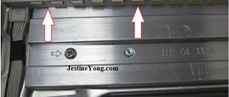
Having looked at the circuit again, I noticed that the LED strip is connected to the cathode not directly to the common, but through a chain of diodes and also 4 resistors. It looks like I was looking in the wrong place, like the previous master, 4 resistors, or rather 3 for the 28-inch model, have values of 2.2 Ohm and two of 1.6 Ohm. In the photo in the red frame are the resistors that are responsible for the current in the circuit, and in the blue frame are those that I soldered.
Now it’s clear why the LEDs glowed without resistors; the diode would still pass current.
In short, we need to finish. To eliminate the short circuit on the tapes, I laid ordinary electrical tape between the body and the tape, the welding tape is not the best, but I hope that the tape will cool normally anyway. Next, I unsolder one 1.6 Ohm resistor from the feedback circuit, and what do you think, the current became about 200 mA
The supply voltage dropped to 50V, but this is because there are now a lot of 3.5V LEDs.
Well, I finally achieved results. Apparently the previous repairman did not bother to check the currents after replacement; in short, he worked according to the instructions, hence the three repairs in half a year. Such a master is always at work.
Well, now you can assemble everything into the case to check the performance of the TV. After assembly, everything worked without problems, the brightness is more than enough for comfortable viewing, but I wanted 250mA currents. To do this, I installed the resistor back at 1.6 Ohm and removed it at 2.2 Ohm. The LED current rose to 220mA, which is just right.
Well, the writing of this article began three days ago, and today is March 30th and the TV has never failed. The heating of the feedback shunts is not significant, the board operates normally and stably. The backlight heats up the case slightly, so electrical tape worked fine for this experiment. Well, time will tell, but I’m returning the TV to my aunt
This is the first experience with LED TVs, and who doesn’t like the collective farm, here you can buy backlight strips cheaper. Long, tedious and persistent, but it was worth it. Further repairs will follow the same rules, I think. By the way, I recommend reading the article about replacing backlight lamps with LED strips and extending the life of an old TV
If you like the material presented, I suggest subscribing to notifications on VKontakte and Odnoklassniki at the top of the page so as not to miss new materials. You can also subscribe to email updates in the column on the right.
I wish you good repairs, fewer craftsmen like that one and all the best. With uv. Edward
Carrying out diagnostics
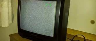
You turned on the TV, and the image disappeared or disappeared, there is just a black screen in front of you, there is sound. To determine what exactly is broken, you first need to independently diagnose the TV, and only then proceed with repairs.
What actions should be taken to correctly diagnose a breakdown? To begin with, simply try unplugging the TV from the mains and turning it on again after a few minutes. If the reboot process did not help, then proceed to the next steps.
Arm yourself with a flashlight or turn it on on your smartphone. And shine the light on a black screen, provided the TV is turned on. If there is sound and when the light is directed, an image in the form of silhouettes is visible, then the ice backlight has failed. This is one of the fastest diagnostic methods.
In this video you will learn more about backlight repair:
To carry out diagnostics in more detail and find out whether the LED backlight circuit has burned out or the ice driver has stopped working.
Attention! To open the back cover of LED TVs, you need to work with complex structures and a set of special tools.
Remove the cover slowly and without rushing. That on Samsung or Elgie TV the algorithm of actions is the same:
- First, separate the stand;
- Then unscrew all fasteners throughout the entire product;
- And only then remove the cover. If this does not work, then look carefully at the surface of the cover and find the location of the bolt that serves as a lock. Unscrew it and only then remove the back cover.
Next, you should definitely check the voltage of the device as a whole, and then only at the ice - the backlight of your TV screen. LED sets are used for backlighting, which provide clear brightness and illumination of the entire screen.
Different manufacturers place them differently. For example, in LG TVs, they are located behind the matrix. First you need to remove the matrix, and only then repair the LED TV.
Nuances of a driver without a current stabilizer
Many users do not install a microcircuit or other similar component at all. But the absence of a transformer leads to voltage and current ripple.
The brightness of the LEDs also changes. The problem is partially solved by a capacitor installed after the bridge. If the stabilizer is not installed, then the minimum ripple value will be 2-5 V.
The option with a microcircuit will get rid of the problem. Therefore, a driver installed by yourself will not be inferior to foreign analogues in terms of pulsation.
Characteristics and differences from LED strip power supplies
Instead of a converter, you cannot use a simple power supply designed for the same voltage and current. Although both devices (driver and LED strip unit) perform almost the same function, there are significant differences.
A simple power supply converts voltage and produces direct current. The tape elements connected to it consist of an LED and resistors. There can be many such nodes in a tape.
It is difficult to control the glow of a semiconductor, since it depends on changes in the current value, and it is constant in a given node. To increase or change the brightness in an LED strip, you will have to simultaneously adjust all the resistors, and this is unrealistic.
The driver is a current stabilizer. The LEDs are connected to it in series. Since a regulating element can be inserted into any stabilizer, the brightness of the semiconductors can be freely changed. To do this, you just need to raise or lower the total current value.
How the device works
The main job of the driver is to create a given current value at the output and maintain it. Any scheme of this type consists of several parts:
- network filter that protects the network from interference;
- capacitor-resistor (RC) or transformer unit to reduce voltage;
- diode bridge for rectification;
- current stabilizer.
A device with an RC filter works like this:
- A capacitor in an alternating current network performs the functions of capacitance. Together with the bridge, it forms a voltage divider and reduces it to the desired limit. The resistor in its circuit serves for self-charging.
- The reduced voltage is supplied to the current stabilizer, and from it to the LEDs.
A transformer unit is a device of a key or other type, controlled by a generator. It can be made on specialized microcircuits, high-voltage key transistors, simple elements or on a PWM controller.
This driver works as follows:
- when power is supplied, the bridge straightens it, and it goes to the switches, on which antiphase voltages are created with the help of windings;
- simultaneously with them, the generator is turned on, which generates pulses and starts the driver;
- the keys, turning on alternately, ensure uninterrupted operation of the device through the feedback circuit;
- an alternating voltage appears on the output winding, rectified by a bridge or 1-2 diodes together with electrolytic capacitors;
- Next in the circuit there is a current stabilizer, to which the LEDs are connected.
Rules for calculating technical parameters
The performance of any device depends on correctly selected components. Therefore, it is necessary to know how to calculate each element of the driver.
The capacity of the quenching capacitor is determined by the formula:
C(uF) = 3200*I load/√(Uinput²-Uoutput²)
For example, for LEDs with a current of 300 mA:
C(μF) = 3200* 300 /√(220²-24²) = 4.367 μF.
The value of the limiting resistance is directly proportional to the amount of current consumed:
- 500 mA – 2.5 Ohm;
- 250 mA – 5 Ohm;
- 125 mA – 10 Ohm.
Knowing these values, you can calculate the resistor for any number of LEDs.
TV for repair
As a test TV to check the functionality of TV set-top boxes and PCs brought in for repairs, we needed an LCD TV, and, as is usually the case, we had to look for a solution on the go without stopping from work. Not long ago I bought a conditionally non-working 15-inch Toshiba LCD TV on Avito, and the price was very modest - only 200 rubles. Just out of curiosity, I now looked up how much this model in working order costs on Avito and was surprised, the price for this already rather outdated model was as much as 3,000 rubles.
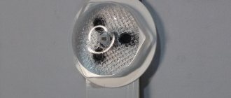
According to the TV owner, when the TV was working, the image disappeared after a minute of operation, but the sound remained. Well, I think everything is clear, as usual, the backlight lamps are most likely very worn out. To check the LCD TV and the matrix itself were disassembled, the problem, as I thought, was in the lamps, which was clearly evidenced by blackening at both ends of the lamp.
Non-working lamp and working lamp (right)
Similar blackening of both bases is familiar to any person who has previously used any household fluorescent lamps as they age and become unusable before going out forever. It was decided to go the simplest and most cost-effective way - to replace the lamps with a regular LED strip in silicone.
Strip 60 LEDs per 1 meter
Reasons for the backlight not working
Failure of the backlight may be due to one of two reasons:
- Problems with the backlight itself.
- Malfunction of the backlight control module (driver).
Sometimes the backlight does not work due to both reasons at the same time, but this is a fairly rare occurrence.
The very malfunction of one or another electronic component of the TV screen most often becomes a consequence of voltage drops in the electrical network. If the power supply of the television receiver receives a voltage that does not correspond to the values required for operation, it may malfunction. Bursts in output current, voltage, frequency, etc. may cause burnout of the backlight itself or the control module. Often the only way out of the situation is to replace burnt out components.
Disassembly
Complete disassembly of the TV depends on the manufacturers. It is difficult to create a single algorithm of actions. So, for example, Samsung models are understood differently. Immediately remove the lid so as not to interfere with the result. First you need to unscrew the 10 bolts that are located along the entire back surface of the TV. Then disconnect the cable and only then put it aside. This manufacturer sets the board in the amount of three pieces. We are interested in the power supply board; the backlight drivers are installed on it.
Important! Before you start disassembling and starting to repair TVs yourself, make sure that no electric current is flowing. Unplug the TV from the outlet.
The most important preparatory stage. It is necessary to clear the surface on it; it can be a stable table, a chest of drawers, at which it will be convenient to work. And carefully collect all small and large parts in one place so that they do not get lost. As for your hands, ideally they should be dry and clean to avoid leaving traces on the internal parts, so it is better to work with gloves. And most importantly, you should not rush while completely disassembling the device.
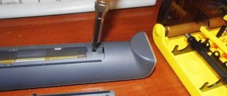
First you need to disassemble the TV
First, disconnect all the cables that are connected to the LCD and attached to the board; to do this, just unscrew the bolt that is located between them. Carefully remove this board and with the same care remove the metal protective casing from the decryptors. They are held on by rubber mounts.
In addition to the back cover, it is also necessary to remove the front frame. To do this, simply unscrew the bolts on all sides. By placing the TV on the back wall, you can easily remove the frame. After removing the frame, turn the TV over carefully, because the matrix is not secured by anything. We remove the decoders, take the matrix in our hands and place it on a separate table.