Despite the fact that in the 21st century, modern televisions have long been in the yard and on store shelves, which have a large number of useful functions, including Internet support, the antenna connector has not been canceled.
A high-quality image depends not only on the brand and model of the TV, but also on the correct installation of the plug, not the antenna itself. If it is assembled incorrectly, the signal quality will suffer. Also, poor signal transmission may be due to an incorrectly selected plug. Provided that you have an excellent plug, a low-quality TV cable, you should not count on watching TV shows, movies without interference and screen flickering.
Looking ahead, we’ll tell you that in nature there are three types of plugs. The most universal of them is the f-plug. It is ideal for transmitting analogue TV, digital TV and satellite signals. At this stage of development, all TVs have two sockets for connecting an antenna on the rear panel.
Today we will tell you in detail how to connect a television cable with a plug and how to properly connect the antenna to a TV. You will learn about this and much more if you read the article from beginning to the very end.
In this article you will learn how to connect an antenna cable
How to connect the plug to the antenna cable?
It is much easier to carry out the procedure when you do not need to look for materials: the cable is laid all the way to the television receiver and there is a spare, working plug.
But what to do if one of the “participants” in the technical operation is not available? Let’s take a closer look at what we need to quickly establish a television signal.
Stage #1 - choosing a cable and plug
Any wire will not work, so to connect the antenna with a television receiver or set-top box for digital signal transmission, you need a special type of cable - coaxial. The optimal resistance parameter is 75 Ohms.
A coaxial cable consists of two main elements - a central conductor and a screen (therefore, the type of cable is called shielded). There is an insulating polymer coating on top, another insulating layer separates the shield from the conductor
To make the core, either copper or copper-plated steel is used. The first option is characterized by low resistance and is typical for equipping satellite television.
The second option can be safely used for switching terrestrial television systems - even taking into account small losses, the signal will be stable. The copper-plated steel analogue costs about 2 times less than the copper one.
Rules for choosing a cable for an antenna:
- There are no special requirements for the manufacturer, but for a satellite dish it is better to purchase a more expensive product from a famous brand, and for terrestrial TV, a domestic one will do.
- Be sure to consider the length of the route. If the distance from the antenna to the television receiver is more than 5 m, the signal loses strength.
- Core thickness standards are 0.5-1.1 mm. The best option is millimeter.
- Pay attention to the quality of shielding. If powerful electrical wiring is located near the antenna route, the screen must be solid, with maximum protection parameters.
- If in indoor conditions the type of insulation does not matter, then for outdoor installation we recommend using only a stronger cable with a PVC sheath painted black.
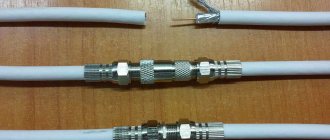
You can't go wrong when choosing a cable marked RG 6 - this is the most popular standard with a 1 mm core, aluminum screen and PVC insulation.
The RG 6 coaxial cable is well suited for self-installation not only due to its technical parameters. Thick core and soft screen allow for quick and precise cutting
In addition to it, you can use the domestic alternative RK 75 or the Italian one - SAT 50 . An option such as RG 59 is not suitable, especially if the signal transmission distance is more than 200 m. Its conductor resistance is too high.
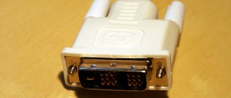
All that remains is to select the plug. Previously, when connecting old-style products, soldering was used. has become unnecessary, since there is a steel plug of standard F. For amateurs with minimal electrical knowledge, it is good because it can be mounted using conventional screwing.
The antenna plug is made of steel and consists of 2 parts. When connecting a TV to a set-top box, the second part is not required, but to connect an antenna, both halves are needed
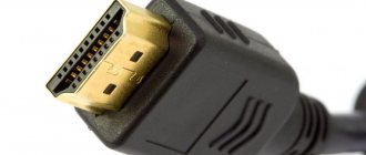
The F-plug is an inexpensive product, and if the old one breaks, there will be no difficulties in purchasing a replacement. LED, LCD, and plasma TVs have a special connector for it on the rear panel.
When you have both the cable and the plug at hand, you can start cutting. This is a simple operation, accessible even to a schoolchild.
Stage #2 - cutting the antenna cable
Now we will find out the nuances of the procedure itself and will analyze step by step how to correctly and accurately connect a shielded antenna cable to the plug.
To remove the insulation, you will need a sharp knife - a construction knife, a stationery knife, an assembly knife, or any knife that happens to be nearby. Wire cutters and pliers may come in handy during the process.
Step #1 – removing the top insulation
At a distance of approximately 1 cm from the end of the cable, use a knife to carefully, pressing lightly, make a circular cut. In order not to damage the screen located under the plastic, do not cut through the insulation. Then, shaking, with little effort, remove the outer insulation.
Under the polymer protective coating there is a screen consisting of thin metallized threads and a layer of foil. It is designed to protect the cable from force fields and other interference that could disrupt the signal.
Step #2 – folding the screen
There is no need to cut off the aluminum braid and foil layer that are located immediately under the insulation.
Carefully, one by one, bend them towards the remaining polymer coating and press firmly against it.
The braiding threads can be collected into one flagellum and placed on any side, or they can simply be bent along the entire circumference. Together with the foil, they form a thin layer that will not be visible at the end of the procedure.
Step #3 - Removing Internal Insulation
Under the screen there is a second polymer layer that separates the central core and the aluminum braid. We also carefully cut it off, trying not to damage the conductor, and remove it.
Before screwing on the fastening nut of the plug, the central copper core must be exposed, and the screen must be bent onto the polymer shell. The main condition is that they do not touch even after installing the plug.
Stage #3 – plug installation
The simplest, but no less important procedure remains - screwing the plug onto the antenna cable. There is no need to cut off the bent screen elements; they should remain under the nut.
We take the plug and unscrew it along the thread to separate it into two halves. The one that has a thickening in the form of a nut at the end, screw the other side directly onto the bent insulation. To make the fit as tight as possible, we help ourselves with pliers.
If the ends of the braid or foil stick out, it’s okay; they can be cut off at the end. The main thing is that the core gets into the center of the hole in the plug
Then, using wire cutters, we cut off the tip of the core so that it protrudes from the half of the plug by 2-3 mm, no more. All that remains is to put on and screw on the other half.
Stage #4 – testing and error analysis
You can find out whether the installation was done correctly in a simple way - turn on the TV. If the signal is stable, there is no interference, the picture is clear, and the sound is clear - everything is done correctly.
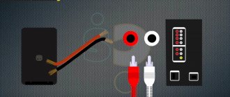
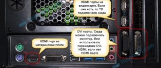
To connect the antenna cable to the TV, on the rear panel of the receiver we find a connector marked “ANT”, “ANT IN” or similar. It is difficult to confuse it with others - it is round in shape and fits perfectly in diameter
If there are problems with signal transmission, you need to find the cause.
Here are a few of the most common:
- The cable length is more than 5 m, and the signal simply weakens before reaching the TV receiver. You should choose a more powerful cable or find a way to shorten its length.
- The antenna is broken . You will have to inspect it if it is installed on a balcony or on the roof. You can call a representative of the service organization if it is responsible for the serviceability of the equipment.
- Installation errors when connecting the plug. Unscrew the plug, remove it from the cable and reinstall it. It is possible that the aluminum braid somehow came into contact with the central core - this should not be allowed.
Poor performance may be caused by a cable failure. For example, it was squeezed tightly by a door or chewed by a puppy. To make sure it is in good condition, you need to check the route along its entire length.
If everything works great, but the cable prevents you from installing the TV near the wall, the straight F-plug must be replaced with an angled one. The principle of installation on a cable is the same
Another reason for a weak signal does not lie at all in installation errors, but is associated with a large distance to the transmitter. Therefore, we will further analyze what an amplifier is and what it is intended for.
Connecting the cable to the TV
To connect the cable to the TV, you must first connect it to the antenna f socket adapter. The connection diagram for a television antenna is very simple and can be found on the Internet. Let's try to describe it in a few words. Connect the cable to the antenna, as well as an amplifier if the antenna is weak. You can watch videos on the Internet for more details.
Every home has not one, but two or three televisions, and there is only one source. What to do in this case? Use a distributor. It has only one input and several outputs, their number depends on how many TVs you want to connect. If the distributor is of poor quality, the TV signal will be poor on all connected devices.
So, unlike Soviet TV models, on modern models all connectors for connecting the antenna cable are located at the back. Each of these connectors is signed. The TV socket is always labeled with the abbreviation ANT. It is into this socket that we connect the cable to the TV.
The socket is very different from other connectors, and it is impossible to confuse them. The latest models of LCD TVs have two sockets for a satellite dish and a simple one. You can connect both, switching from one television to another will be done via the remote control.
How to connect digital TV? To do this, you need a tuner that will pick up the signal. Some models are already produced with a built-in tuner. For earlier models, you need to buy a separate set-top box and connect it to the TV. It is recommended for absolutely everyone to connect to digital TV, because from January 1, 2019, analogue television will stop broadcasting. Digital TV connected to everyone free of charge gives the opportunity to watch 20 channels, including federal TV channels.
How to connect a satellite dish? It is recommended that only specialists set up the dish and connect it. To do this, you need to purchase the entire kit, receiver and plate. This connector also has a round shape, but differs visually from the standard ATN, and the inscription LNB (ANT 2 IN) has an external thread.
A list of broadcasting TV formats that the TV supports can be found either in the specifications, or by looking at what inscriptions are on the back cover. You can install an f tv adapter on old antennas.
With plug
How to connect a TV antenna at home? Let's take a step-by-step look at the instructions for setting up a home TV antenna. We connect the TV plug to the TV, the cable to the outlet. If it is an old model, then use a plug adapter. If it is in good condition, then it will be enough to twist it a little to set up a clear image without interference.
Connecting a standard or satellite television signal to a TV is not difficult if no action was disturbed during the use of the antenna cable connector for the TV and the cable itself was not damaged.
You can also resort to using adapters for f, TV socket adapter, if you have a tulip antenna plug. When connecting to TV, pay attention to cable adapters.
There is a version with and without plug
The bnc plug is needed to connect the camera to the TV for video surveillance. BNC connectors are different. There are more than three types of them: screw, compression, solder, screw-on, with a terminal block. And installation depends on the type you use; you may have to use special adapters.
Types of antenna plugs
The plug is an important design element. It is used to connect the television cable to the socket. It transmits current from the shield or antenna. It is very important to choose the right antenna plug because it is a conductor. It is necessary to thoroughly understand this topic so that questions do not arise.
Any plug is like a bushing. Instead, they previously soldered a special connector to connect the TV. Now techies have come up with different types of plugs, and also figured out what distinguishes them.
The plug has a huge number of advantages, including:
- Using a special braid, the uniformity of the supplied current is ensured. This braid also prevents signal loss or poor-quality connection;
- The plugs can be combined with absolutely any type of television signal, including the most complex ones. Can be connected to both cable television and digital;
- Connecting the plug is very simple. Any user can cope with this task, as there is nothing complicated about it.
In general, there are two types: modern F-plugs and old designs. The second option is not divided into subtypes, so it is worth considering the first option, since it is the most common on the market and is also supported in most devices.
In total, modern technicians and many users distinguish three types of F-plugs. Each of them has both its advantages and disadvantages, which are worth discussing in more detail below.
The first type is screw-on plugs. Such designs are quite popular, and they look like pressed-on nuts with an additional reinforcement. They are widely used because they connect very quickly and easily. Their operation is simple and understandable to any user, so they are often used when connecting cables.
Despite many advantages, such connectors also have disadvantages, including:
- Small thickness. It is difficult to crimp such cables with a ring, which may cause problems with installing the structure;
- Their shortened thread does not allow the cable or wire to be tightly fixed in the structure;
- If you screw the connector incorrectly, you can break the braided conductors and even twist the protective layer. This is difficult to prevent.
Although screw-on plugs are simple in design and quite easy to use, they have a number of disadvantages that force users to consider other types and options.
The second type is crimp type. Crimp plugs are also simple in design, with some users even saying that they are much easier to attach than the first type. It is enough to use the basic rules for preparing the cable, and then insert the wire into the hole of the convector, cut through the foil and fix it. Fixation is carried out using a crimping movable sleeve, which is included in the kit.
The bent layer of wire in the plug must be distributed evenly so that there are no problems with further operation.
Also, such plugs have their drawbacks in the form of a complex design. Beginners will find it difficult to handle this type of plug, as well as to evenly distribute the cable.
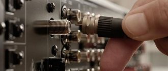
The third and final type is the compression plug. If we consider all types, then this type is the most reliable. At least that's what television professionals think. Despite all the reliability, the use of such plugs is accompanied by professional tools, as well as special equipment. If the user does not understand the circuits and mechanics, he will not be able to attach and connect such a plug.
The whole process takes place using special forceps. It is necessary to correctly insert the cable into the connector, and then use pliers to stretch the cable along the entire crimp sleeve, then you need to secure the structure. This is a rather complicated process that not every user can handle.
Thus, distinguishing between three types, the user must choose the antenna shaker that suits him. Each has its own advantages and disadvantages. This is worth talking about further.
I DETECT YOUR AD BLOCKER!
I understand that you cannot turn off your ad blocker.
Simply because I don’t want to change the order of things. But like any sane person, I want to offer a compromise. I GIVE YOU GIFTS! PAY ATTENTION TO ADVERTISING! NO OFFENSE! BE MORE HUMAN TO THE AUTHORS OF ARTICLES! ISN'T IT NICE TO DO SOMEONE GOOD?
INCREASE YOUR PERCENTAGE OF POSITIVE KARMA. WE WILL ALL BE GRATEFUL!
We have a minimum of advertisements on our page. At the beginning of the article and at the end! So it won’t hurt to read and learn something useful!
Whitelist this website or disable your ad blocking software!
THERE WILL BE SPECIAL GIFTS FOR SUBSCRIBERS!
THIS IS EASY AND FREE TO DO. ALSO, GIFTS WILL BE TO ALL FRIENDS WHO DO NOT TURN ON AD BLOCKING! And they pay attention to advertisements. You will find the GIFT above the bottom block (footer), or to make it completely clear, immediately after the comments. Of course, when you disable the blocker. The gift will be updated and have different themes.
A tiny team of authors already thanks YOU for your kindness and understanding of the situation. The advertisements contain useful information.
GOOD LUCK FRIENDS!
Used for installation on coaxial cable. As a result, the cable is connected to the receiver.
Also for disk drive, converter or additionally used with adapters.
The connectors are installed on the cable after appropriate cutting and do not require soldering of contacts.
Inner diameter - 6.5 mm.
F connectors have been specially designed and developed. For joint use with television and satellite equipment.
The result is low-cost high-frequency connectors. Which are quite simply and quickly installed on the cable.
I note, without using special equipment and without soldering contacts. This allows them to be installed on cables in remote locations. For example, on the roof of a house, when installing a satellite dish there.
It's not particularly convenient to work with a soldering iron on the roof.
F connectors use the center core of the coaxial cable directly. To make the connection, they act as a kind of screen.
By winding the cable around the braid to act as an electrical contact. These connectors allow operation at frequencies up to 2200 MHz. This fully satisfies the requirements in terrestrial, cable and satellite television systems.
F connector F-116.
F connector (“barrel”) is used to splice two pieces of coaxial cable. Using two F connectors installed on the cable.
The connection of two cables is made through mechanical contact and does not require soldering. This F connector has been specially designed. For use in conjunction with satellite and television equipment.
Allows you to connect two cables if the length of one of them is insufficient.
This is something to keep in mind!
Such a connection in open areas may be affected by precipitation. And this will undoubtedly lead to a deterioration in contacts. Therefore, you need to take care of high-quality sealing of the connection.
Angled F female (angular F female connector).
The connector is used to connect a coaxial cable to the DVB-T2 or DVB-C output connector of the tuner.
Also, the RF modulator of an terrestrial, cable or satellite receiver. Due to the right angle, it reduces cable bending.
The angled F female connector is installed on a coaxial cable quite simply. Using an F connector without using a soldering iron.
To install this connector on a coaxial cable, you will also need to purchase a separate F-connector.
Angled F male (angular F male connector).
The connector is used to connect a coaxial cable to the antenna input, DVB-T2. Also DVB-C tuner input connector. Or the RF modulator of an terrestrial, cable or satellite receiver.
Due to the right angle, it reduces cable bending. The angled F male connector is installed on a coaxial cable quite simply. Using an F connector without using a soldering iron.
To install this connector on a coaxial cable, you will also need to buy a separate F connector.
How to install a type F connector (connector).
When installing and maintaining satellite dishes, there is no escape from cables. The signal level directly depends on the quality of the embedded cable.
The worse the cable is sealed, the more the signal will weaken at the transition. And this! Agree it is very important! Let's take a look and gain some knowledge, here .
Features of cable routing
The television cable “comes” into the apartment from the floor panel and is routed through the television receivers available in the house. To correctly install a TV cable throughout your apartment, you should follow some recommendations.
The main elements of a TV cable in stripped and completely exposed form
To avoid signal interference, it is recommended to place the cable away from the electrical wiring. Telephone wire or Internet cable do not interfere with the normal passage of the TV signal, and therefore the general installation of these communications in one cable channel is allowed. If it is impossible to avoid placing an electrical cable together with a television cable, then you should purchase a TV cable with a core diameter of over 1 mm with a double protective screen.
Throughout the apartment, the cable should be pulled in one piece, avoiding any connections or twists that affect the quality of the picture. Crossing cables with electrical networks is not recommended, but if this cannot be avoided, then the intersection should be arranged strictly at an angle of 90°.
Most common models
Today there are a large number of RF connectors, the production of which is standardized by Russian and international standards. However, equipment is produced according to the companies’ own standards. It is quite difficult to understand such a variety, so when faced with choosing the required type of connector, you should seek the help of a specialist.
For a general idea, let's try to look at some of the most popular types.
N-connector is one of the first screw-type microwave connectors. Developed more than 8 decades ago, today it has a large number of modifications, some of which can operate at frequencies up to 18 GHz. The characteristic impedance of such connectors is predominantly 50 Ohms. An example of such a connector is N-111/5D (“male”) or NM-1/2 (N-male) with a hex key.
N-male
N-female
BNC-connector is a bayonet connector that has found application in connecting radio measuring instruments and equipment. In addition, it is used in Ethernet networks built using 10BASE2 technology. The RF connector is produced in two versions (50 and 75 Ohms) and operates at frequencies up to 10 GHz (50-ohm version).
TNC-connector - an option similar to the previous one, only the bayonet connection is replaced by a threaded one. This is a higher frequency connector, capable of operating at frequencies up to 11 GHz. Connectors of this type are available with a characteristic impedance of 50 Ohms.
SMA-connector – distinguished by high frequency characteristics. The characteristic impedance connector is capable of operating at frequencies up to 18 GHz, and for some modifications the upper limit is 26.5 GHz. The SMA type connector has a threaded connection and, when used correctly, can withstand up to 500 connection cycles. The housing of the SMA (male) connector is made in the form of a hex nut; it is recommended to use a torque wrench when tightening. The connector model S-111F can be called a typical and affordable SMA connector, which can be purchased in our online store.
PR-SMA-connector – is a reverse version of the SMA connector for the cable. By swapping the core and braided cable that powers the remote device, it helps protect the circuit from DC current.
CRC9-connector is a miniature version of a high-frequency connector. This is a push-in connector, often used with various Huawei 3G and 4G modems.
In addition to CRC-9, other connectors can be used in 3G/4G USB modems. Read more about how to choose an adapter (pigtail) for a modem in our article.
The RJ-45 connector, although not a high-frequency connector, is actively used in creating computer and telephone networks. By providing termination for UTP/FTP cables, simply called “twisted pair,” it guarantees a reliable connection that prevents the connector from accidentally falling out of the socket and is installed without any problems using the crimping method. You can buy an RJ-45 connector using the link in our online store.
Plug information
In general, the plug design consists of two parts - the F-connector and the adapter. It is the connector that is put on the cut cable, and the adapter is screwed into the connector. The adapter is then connected to the antenna socket of the TV receiver or digital set-top box.
Previously, plugs in plastic, rubberized shells were used. Inside, the core and screen were fastened through soldering, clamping and screwing.
Nowadays it is much easier to connect the antenna cable to the plug. You just need to properly prepare the cable and secure (put on) the plug on it.
Depending on where the TV is installed, you can determine the type of F-adapter that is needed. If the television receiver is on a cabinet or table, and there is a lot of space in the back, then any adapter, including a straight one, will do. If there is enough space behind the equipment, there will be no kinks in the cable and there will be enough space for connection.
But when the TV receiver hangs almost flush on the wall, you need a corner adapter.
Otherwise, with a straight plug, you will have to bend the cable greatly. This can lead to signal loss and even damage to the conductors inside.
Components that will be needed to complete the work
To route the signal between two TVs you will need:
- Splitter (splitter) for two outputs . This part is designed to divide the signal into streams. It has one antenna input and two TV outputs. If you purchased a splitter for three or more outputs that you do not plan to use, then cover the free outputs with ballast resistors with a resistance of 75 Ohms (you can buy them at a radio parts store).
- 5 F- connectors. One connector is required to connect the antenna cable to the splitter and 2 pcs. for every TV cable.
- 2 plugs . These adapters are designed to connect television cables directly to televisions.
- 2 TV cables . The length of the cables will depend on the distance of the splitter to the TVs, which in turn depends on the distance of the antenna to the splitter. We advise you to measure these distances in advance and buy a cable with a reserve.
How does a television cable work?
A standard coaxial cord consists of the following required elements:
- the central core, it is in a durable polypropylene sheath, in most cases made of copper or copper-plated steel;
- a screen consisting of aluminum foil is designed to protect the core from electromagnetic interference;
- to ensure that the wire is not affected by external fields, an outer braid is attached, it forms the outer part of the coaxial element;
- The wire is also protected from mechanical damage and destruction; it consists of a polyethylene coating on the entire cable.
All elements of the wire are important, so you should thoroughly prepare each part of the connecting sections.
Experts call the cable connection “cutting.” During this operation, selected areas are cleared of insulation elements and prepared for future connection.
Types of RF connectors
GSM-Repeaters.RU » Types of RF connectors
For high-quality operation of a cellular signal amplifier, receiving and distributing antennas, and routers, a good cable assembly is simply necessary. And one of the most important links here are the RF connectors. How to choose the right coaxial connectors, how does one type differ from another? All this will be discussed below.
BNC
This is what we call a bayonet connector. It was created back in the first half of the 20th century and is one of the founders of RF connectors and is widely used to this day. The main feature is the connection due to the original clamp with a latch. This simplifies operation with frequent disconnection and connection and guarantees reliable contact (signal loss - no more than 0.3 dB). The maximum cable diameter along the sheath is 7 mm. For networks with a characteristic impedance of 50 Ohms, a frequency of no more than 4 GHz is permissible.
TNC
The threaded BNC variant, developed in the late 1950s, is capable of operating at frequencies up to 11 GHz. Also among the positive differences of the format is better contact, especially in conditions of high vibrations. Cable diameter – 3-10 mm.
F
Another widespread type. The part that fixes the cable with a diameter of 5-8 mm is made in the form of a nut that is screwed onto the screen (outer conductor). In this case, the role of the plug is played by the bare central core, which narrows the range of feeders used (there must be a monolithic core resistant to corrosion and wear). Most often used in television networks at frequencies up to 2 GHz. The main advantages: simplicity and price.
FME
A smaller analogue of the F-standard. It was developed for connecting portable equipment and has found wide application in cellular communications. The diameter of the cable along the sheath should be from 3 to 5 mm. Operates in the frequency spectrum up to 2 GHz. FME is often used with RG-58 cable.
N
One of the most popular connectors, since its characteristics most fully meet the requirements for microwave signal transmission. There are various subtypes depending on the installation (crimp, solder, clamp). The N-connector can operate effectively at frequencies up to 18 GHz. Suitable for cable diameters from 3 to 10 mm.
SMA
Subminiature connector A, characterized by small dimensions (cable diameter - 3-5 mm) and a high operating frequency level - 18 GHz. Initially designed for a characteristic impedance of 50 Ohms. Stainless steel construction includes a durable metal plug and threaded mounting (hex nut).
RP-SMA
The abbreviation stands for “reverse-polarity Sub-Miniature version A”. Suitable for use with RG-58 coaxial cable. The small-sized reversible connector (reverse polarity SMA) is widely used to connect WiFi equipment. As a rule, the feeder is fixed using crimping.
7/16
Modern, large socket. The marking numbers indicate the following: 7 mm – outer diameter of the central core, 16 mm – inner diameter of the braid (outer conductor). The connectors are used for powerful equipment (mainly used at cellular base stations) and have a reliable threaded connection with a high degree of moisture and dust protection. Operating frequency – up to 7.5 GHz (flexible cable) or 18 GHz (semi-rigid cable). An alternative designation for the series is L29.
In addition to division into series, there are other factors that determine the appropriateness of the choice.
Type:
- plug (plug, male, plug, male);
- socket (socket, “mother”, jack, female).
By polarity:
- standard (straight) polarity: “male” comes with a pin, “mother” comes with a socket;
- reverse polarity (RP marking): “male” – socket, “female” – pin.
By design:
- straight;
- corner.
According to the type of fastening of the central contact:
- for soldering (the contact is soldered with tin to the central core of the cable);
- crimp (the contact is put on the central conductor and crimped).
According to the type of housing fastening (metal braid of the cable to the housing):
- Clamping . The cable contact area is equipped with a threaded metal bushing. It is screwed into the body, exerting pressure on the pressure sleeve. The advantage of such a connector is the relative ease of installation, no need for special tools (only a wrench, a utility knife and scissors). The disadvantage of this choice is the average connection reliability.
- Crimping. Unlike the previous type, the part of the connector responsible for fixing the braid does not have a thread. The feeder is secured using a crimp sleeve(s). Crimping is done using a special tool - a crimper. Crimp connectors have good mechanical strength and good electrical contact.
By type of connected cable:
- F – for RG-58 or other cable with a diameter of 3 mm;
- /5D – for cable 5D-FB/CNT-300/LMR-300 or other with a diameter of 6.5-7 mm;
- X – for RG-213 cable with a diameter of 10 mm;
- /8D – for cable 8D-FB/CNT-400/LMR-400 or other with a diameter of 10-11 mm;
- /10D – for cable 10D-FB/CNT-500/LMR-500 or other with a diameter of 13 mm.
Result:
If you need a cable for video surveillance, satellite or terrestrial TV, then an inexpensive 75 Ohm cable is suitable. Brands SAT-703, RG-6, RG-59. If you need a cable for a local Ethernet computer network or for wired telephony, then use a UTP4 twisted pair cable (indoors) or FTP4 (shielded, outdoor). If you need a cable for GSM equipment (GSM repeater, GSM alarm, GSM gateway, GSM phone), then for short distances (up to 10m) a 3mm RG-58 cable will be sufficient, for lengths up to 30m - a 5D cable -FB or other analogue 50 Ohm 7mm thick. For longer lengths, as well as for permanent structures, we recommend 11mm 8D-FB cable. If you need a cable for 3G equipment (3G repeater, 3G antenna, 3G modem, 3G router), then for short distances (up to 10 m) a 7mm 5D-FB cable is suitable, for longer lengths - an 8D-FB cable . If you need a cable for 4G equipment (4G antenna, 4G modem, 4G router), then for short distances (up to 10m) a 7mm 5D-FB cable is suitable, for lengths up to 20m - an 8D-FB cable. Large cable runs on 4G are not recommended. For premium systems, a 13mm 10D-FB or 7/16-inch cable is used. For professional systems (for example, base stations) - cable 7/16 or thicker.
Which antenna plug is better?
The answer is clear: the best of the three considered plugs for television coaxial cable is the F-plug. This is easy to see in the photographs above, even without special knowledge.
As you can see, the antenna plug of the old design and the Soviet antenna plug have a small section of the central core of the cable that is not covered by the shielding braid. This disrupts the uniformity of wave impedance, which leads to minor losses of the television signal.
The F-plug does not have an open section of the central core of the antenna cable. Another advantage of the antenna F-plug is ease of installation. With a minimum set of standard tools and no skills, almost anyone can correctly attach the antenna F-plug to the cable.
Types, classification and main characteristics
Today, there are a large number of RF connectors, differing both in the method of articulation of both parts and in design. According to the first sign they are:
- threaded, with connection via a threaded connection;
- bayonet, providing a quick connection based on the bayonet principle, from baïonnette (French) - bayonet;
- plug-in, an example of such a connector is the familiar television plug.
The design is determined primarily by the purpose of the connector, according to which they are:
- cable, installed at the ends of cables;
- instrument mounted on instrument housings;
- instrument-cable (the name characterizes the purpose of the RF connector);
- mounted on printed circuit boards.
The latter are represented by SMD connectors, soldered onto the board using the surface mount method.
The main parameters characterizing the suitability of an RF connector for certain purposes include:
- the magnitude of wave resistance;
- operating frequency range determined by the upper limit;
- maximum SWR (standing wave ratio).
In practice, the list of parameters is much longer. This typically includes the operating voltage range, dielectric strength, and insertion loss level.
Do you need an antenna amplifier?
The question of purchasing an antenna amplifier arises when signal loss becomes systemic.
Due to insufficient transmission, the receiver or digital tuner cannot cope with the processing of the organization. You may see a “no signal” or “weak signal” message on the TV screen.
If communication is carried out without an electronic intermediary, then signal loss can be expressed by the absence of sound, a “freezing” image, an unclear or “pixelated” picture
If the signal is too weak, an antenna amplifier is installed, the main purpose of which is to make the signal more powerful. It is integrated into the TV system on the section of the route between the television receiver and the antenna.
Most often, external devices are used that cut into the antenna cable using two connectors. More “serious” amplifiers look like a set-top box, and some have an additional power supply
Active type antennas already have built-in amplifiers; installing a second one will not help. Also, it will not cope with its function if the antenna is broken or, due to its parameters, is simply not able to receive a signal at a long distance.
In the area of stable reception, the amplifier can even cause harm, since too powerful a signal is also one of the reasons for the failure of the digital tuner.
We connect an antenna with an amplifier to two TVs
The antenna amplifier must be additionally powered. You can power it in two ways:
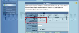
- We use an active splitter. The active splitter has a power pass, which is indicated on the device itself with the words Power Pass. In fact, the antenna can be powered through such a splitter. It is enough to set the “antenna power” mode in the menu of the digital set-top box (which is powered from the network using a power supply), and the antenna amplifier will be powered through the active splitter.
- We use our own antenna power supply. In this case, you can use a regular (passive) splitter, but in addition you will need to connect the antenna amplifier power supply to it. To do this, we take two connectors of the male/female type. We screw one onto the input of the splitter, and connect the other to the power supply. Then we connect the power supply and the splitter. Thus, the circuit will be the same as in the case of an antenna without an amplifier, but with an additional link in the form of a power supply (as in the image).
Please note that the remaining steps for mounting an antenna with an amplifier will be the same as for the non-amplifier model. We can recommend an inexpensive antenna with an amplifier REMO BAS-1159-5V Orbita-19 SUPER - it comes with a power supply.
How to extend a TV antenna cable
Twist
The easiest way to connect two pieces of cable. It does not require any additional devices. However, along with its simplicity, it is also the least reliable, and it doesn’t look very good either. Twisted contacts can oxidize over time, which will lead to a significant deterioration in the quality of the image transmitted over the television line. This option is more likely to be suitable as a temporary measure when it is not possible to extend the cable in any other way.
For twisting you need:
- Remove the outer insulation by about 5 centimeters and, being careful not to damage the integrity of the braid, move it away;
- Remove the insulation running inside the cable, thereby providing access to the core running 2-3 cm in the center;
- Carefully twist the cores of the extension cable and the piece used for extension together, and cover this area with electrical tape;
- Twist the screens at the connection point and carefully insulate this area.
A particularly important point with such a connection is the complete exclusion of the possibility of contact between the central part of the cable and the screen.
Using a splitter
Splitter is a special device that provides branching of a television signal. It is used when it is necessary not only to make the antenna cable longer, but to create a new branch that allows the signal to be sent to another TV.
To implement this method, you need to purchase the splitter itself and, depending on which model you chose, F-connectors or TV plugs. Particular attention should be paid to the labeling of the device. The splitter is equipped with one hole for installing a wire stretching from the antenna - it is marked with the engraving “IN” -INPUT and several outlet holes - for cables stretching to TVs.
When using this method, it is important to correctly separate the ends of the cable coming from the antenna and install them in the connectors. To do this you should:
- Remove the insulation passing from above by about 2-3 cm and carefully move the braid in the direction opposite to its location;
- Having made an indentation from the edge by 2-3 mm, remove the insulation that runs inside, thereby exposing the core located in the center;
- Carefully secure the F-connector to the cable (if it is not tight, wind it with foil);
- Cut the core running through the center so that its protrusion beyond the end of the connector is no more than half a centimeter;
- Carry out similar actions with the other end;
- Connect the cables to the splitter, paying attention to its markings.
Using an adapter
The use of a conductor makes it possible to perform it in the most aesthetically pleasing and high-quality manner. This method is used mainly in cases where you simply need to extend an existing line. The order of operations performed in this case is almost completely identical to the previous method. The only difference is that you will additionally need to purchase an adapter and two F-connectors.
In this case, you must act as follows:
- place the F-connectors at the ends of the antenna cable (same as in the previous method);
- connect the parts of the line by aligning the F-connector with the adapter.
Use of soldering
Soldering is another option that can be used to connect wires. It does not require the use of a large amount of auxiliary equipment, it is non-separable and inexpensive. In order to solder the cable, you will need a soldering iron and a minimum of skills in handling it. Before soldering, you should perform operations similar to preparing for twisting and only then solder.
We looked at the simplest and most common ways to extend the antenna cable for a TV. Which one is most suitable for each specific situation - decide for yourself. If you need to make an emergency connection, use twisting, and for the most durable and reliable connection, use a splitter or adapter.
TV
Installing the plug on the cable
To install the plug connected by a television cable, we first install connectors for connection on the prepared section of the wire, that is, a special cylinder that has an internal thread and is attached with a nut, and on the outside there is a threaded hexagon. To secure everything correctly, we need tools: pliers, a sharp knife and wire cutters.
After removing the outer protective shell, we fold the foil and bend it halfway towards the protective layer. Then we cut the next layer to free the central wire. Let's expose it completely. The cleanup is considered partially completed.
At the next stage, insert the plug, the first half. At this stage, it is advisable to use pliers so as not to rub the callus on your fingers by constantly scrolling.
Important! If you cleaned up more than was necessary, then don’t worry. Trim the excess piece at a 45 degree angle. The main thing is to carry out all manipulations accurately and with a confident hand.
Don’t forget to choose the appropriate connector.
The main thing is to choose the right F – connector, it must have a thread inside. Thus, a plug was installed into the television cable.
After all the above steps, when we put on the plug, we can proceed to connecting the cable to the antenna, and, consequently, the antenna to the TV. Crimping is a necessary step that cannot be avoided.
Instructions for crimping - connecting with your own hands
SO, the process is not complicated, but you need to do everything carefully, otherwise we will simply ruin the antenna cable, I will list it point by point:
- We take a knife, step back from the end of the cable about 1 - 1.5 cm, and carefully cut only the upper plastic winding in a circle - it is important not to damage the “screen” and the aluminum part underneath it! Let's take it off!
- Now we have an aluminum winding and a screen in front of us; we need to bend them onto the cable itself.
- Next, we have an insulator in front of us, we retreat 0.7 - 1 cm and cut it to the main core, the main thing is not to damage it either. It is certainly thick and durable - but without fanaticism! We remove the insulator.
- We take the F connector and simply screw it onto the bent insulator, it is important that the central wire falls into the hole in the center.
- In fact, everything is ready, you can connect to the receiver or screw the antenna connector on top. Who needs what?
As you can see, there is nothing complicated, but for those who do not quite understand, I present a video version.
Installation of television antennas
Installation (sharing my experience). You have become acquainted with the various types of television over-the-air antennas. You can independently choose the antenna that best suits your conditions for receiving a television signal. All that remains is to install the antenna and you need to do it correctly, since otherwise all your efforts may be in vain. The antenna installation process will include several points:
1. Antenna assembly.
Antenna assembly.
Connection errors
- A situation where the screen includes a layer of foil. The outer side of the foil, which is turned towards the braid, is treated with aluminum spraying. The reverse side does not conduct current. Therefore, when the shielding is folded back, the foil can completely cover the braiding threads. Because of this, there is likely to be a lack of contact between the connector and the braid. To be sure there is contact, you can twist the foil or remove it completely.
- Failure to comply with the connection rules, which causes a short circuit. At best, the TV will not pick up any channels. At worst, a short circuit will occur in the TV or set-top box. This can lead to equipment failure.
- If the plug is screwed on with pliers, it is not recommended to squeeze the tool too hard. Many adapters are made of low-quality metal. Strong mechanical stress will lead to a crack or complete disintegration of the connector.
About the Angle Design Plug
Judging by the reviews, there are times when there is a need to move the TV with the antenna plug already inserted closer to the wall, which is problematic. In such a situation, a special plug with an angled design will help out.
You can buy it at an electrical appliance store. To connect this product, the technology described above is applicable. If the TV owner does not want to use a plug connection, then soldering will be the optimal connection method. However, for a high-quality signal, the soldered area should be smaller.
In addition, if you need to quickly connect the TV, this will be problematic. In this regard, the plug connection is considered the most convenient.
Cable preparation. Video
The video below will tell you how to prepare a TV or satellite antenna cable for use.
You can extend and branch a television cable with your own hands if you follow the rules described in the article.
Connecting your TV to an external signal yourself will not be difficult if you figure out the antenna plug. It is with the help of this device that the receiver socket is connected to a TV cable, which transmits high-frequency current from the panel on the landing or the attic antenna to the apartment. It is important to choose the correct diameter ratio and technical characteristics of the conductor, accurately cut the end of the cable and screw on the plug.